Trace Heating Testing, Maintenance and Fault Finding
Published 28 Jul 2026
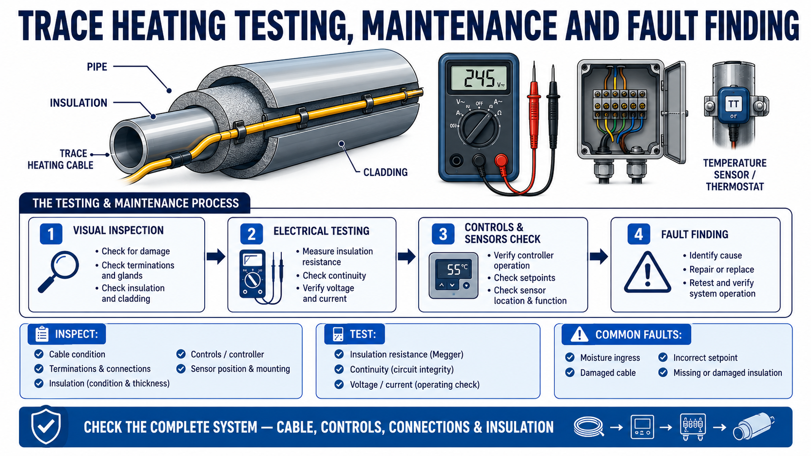
Electrical Heat Tracing Inspection, Testing & Troubleshooting
Quick Navigation
Why Preventive Maintenance Matters
When Should Trace Heating Be Tested?
Safety & Preparation
Visual Inspection
Electrical Testing
Controllers, Sensors & Limiters
Insulation & Weatherproofing
Common Trace Heating Faults
Fault-Finding Process
Preventive Maintenance Schedule
Testing Records & Documentation
Hazardous-Area Systems
Frequently Asked Questions
Technical Support
Trace Heating Testing, Maintenance and Fault Finding Overview
A reliable trace heating testing programme checks the condition and performance of the heating cable, electrical connections, controls, sensors, insulation and weatherproofing before a fault develops into frozen pipework, lost production or process instability.
For readers who need the underlying operating principles first, see how an electrical trace heating system works. This guide remains focused on inspection, maintenance and fault finding rather than repeating the general definition of trace heating.
The maintenance objective:
- Confirm that the heating cable circuit remains electrically sound
- Identify physical damage, moisture ingress and degraded components
- Verify that controls and temperature sensors respond correctly
- Check that insulation and cladding continue to limit heat loss
- Compare current operating data with commissioning records
- Correct developing faults before cold weather or critical production periods
Safety-Critical Work
Electrical isolation, testing, repair and recommissioning should be completed by suitably competent personnel. Follow the current installation and maintenance instructions for the specific heating cable, connection system, controller and area classification. Do not energise a visibly damaged or unverified circuit.
Why Does Trace Heating Preventive Maintenance Matter?
A trace heating circuit can remain energised while delivering less heat than the process requires. A failed sensor, damaged cable, missing insulation or incorrect controller setting may not be obvious until temperatures fall or a product begins to thicken, crystallise or freeze.
Preventive maintenance helps identify faults while the system can still be inspected, isolated and repaired safely. It also provides evidence that the circuit, control equipment and protective devices have been checked against the design and operating requirements.
When Should Trace Heating Be Tested?
Testing requirements vary by manufacturer, project specification, site risk and application. Typical inspection points include:
Recommended test stages:
- When heating cable and components are received
- Before the cable is installed
- After installation on the pipe but before thermal insulation is fitted
- After insulation and weatherproof cladding are complete
- During commissioning before the circuit enters service
- At planned preventive maintenance intervals
- Before seasonal winter operation
- After pipework repairs, insulation removal or maintenance nearby
- After a trip, alarm, unexplained temperature loss or suspected cable damage
The existing trace heating installation guide covers the installation sequence. The checks below focus on maintaining and diagnosing a system once installed.
Safety and Preparation Before Testing
Before opening enclosures, disconnecting circuits or applying test equipment, confirm the site isolation procedure and the limits of the work.
- Identify the correct circuit, cable type and system drawings
- Review the manufacturer’s latest installation and maintenance instructions
- Confirm the supply voltage, protective device and controller arrangement
- Check whether the location is safe or classified as a hazardous area
- Obtain the required permits and verify safe isolation
- Allow hot pipework and process equipment to reach a safe working condition
- Use test equipment suitable for the circuit and environment
- Record ambient and pipe temperatures where they affect the readings
Do Not Use a Universal Pass Value
Insulation-resistance, conductor-resistance and current readings must be assessed against the cable manufacturer’s instructions, circuit length, test voltage, temperature and commissioning records. A value copied from another cable type or project may be inappropriate.
1. Complete a Visual Trace Heating Inspection
A visual inspection should cover all accessible parts of the circuit before electrical testing begins.
| Inspection Area | What to Check |
|---|---|
| Heating cable | Cuts, crushing, abrasion, overheating, tight bends, unsupported sections and unauthorised repairs |
| Power connections | Loose covers, damaged seals, moisture, corrosion, overheating and secure cable entries |
| End seals, splices and tees | Correct assembly, physical damage, water ingress and compatibility with the cable |
| Junction boxes | Condition, gland entries, terminals, earthing, identification and enclosure integrity |
| Controllers and limiters | Display condition, setpoints, alarm status, sensor inputs and signs of overheating |
| Pipe fittings | Cable routing around valves, flanges, supports, pumps and removable sections |
| Thermal insulation | Missing, compressed, wet or damaged insulation and incorrectly refitted jackets |
| Weatherproof cladding | Open seams, damaged seals, missing fasteners and entry points for water |
| Labels and records | Circuit identification, warning labels, drawings and previous test results |
2. Complete the Required Electrical Tests
The exact test sequence must follow the cable and component manufacturer’s instructions. Common checks include:
Insulation Resistance Testing
An insulation resistance test is used to check the integrity of the cable insulation and jacket system. Readings can be affected by cable length, moisture, temperature, test voltage and the connected equipment, so the approved procedure and acceptance criteria must be used.
Conductor Continuity or Resistance
Continuity and resistance checks help confirm that the heating circuit is complete and that the measured resistance is consistent with the cable type, designed length and temperature. Unexpected readings can indicate an open circuit, short circuit, damaged conductor or an incorrect installed length.
Supply Voltage and Operating Current
Once the circuit has passed the required pre-energisation tests and can be energised safely, measure supply voltage and operating current under controlled conditions. Compare the results with the design information and commissioning record rather than relying on a generic expected value.
Protective Device Operation
Confirm that the circuit protection and earth-fault or residual-current protection are appropriate for the system and have been tested in accordance with the site electrical maintenance procedure.
3. Check Controllers, Sensors and Temperature Limiters
A sound heating cable cannot maintain the correct temperature if its control or sensing system is incorrect.
Controller and sensor checks:
- Confirm the required setpoint and any alarm thresholds
- Check whether the controller is sensing ambient, pipe or product temperature
- Verify that the sensor is in the designed position and securely attached
- Inspect sensor cables for damage and unsuitable routing
- Check displayed temperature against an appropriate reference measurement
- Confirm that outputs switch or modulate as intended
- Test high- and low-temperature alarms where provided
- Verify limiter settings and manual reset functions where applicable
- Review event logs and historical alarm records on monitored systems
For hazardous-area temperature regulation, see the available heat trace thermostats and digital temperature controllers and trace heating temperature limiters.
4. Inspect Insulation and Weatherproof Cladding
Thermal insulation is part of the heating system, not a separate cosmetic layer. Wet, damaged, missing or compressed insulation increases heat loss and can make a correctly powered cable appear undersized.
- Check the full pipe length for missing or displaced insulation
- Inspect cladding seams and penetrations for water entry
- Confirm removable jackets are refitted after valve or instrument maintenance
- Look for crushed insulation at supports and access points
- Check that cable exits and sensor penetrations remain sealed
- Investigate staining, corrosion or ice formation that may indicate moisture
If the original duty or insulation has changed, the system may require a new trace heating heat loss calculation rather than a simple electrical repair.
Common Trace Heating Faults and Likely Causes
| Observed Problem | Possible Causes | Initial Checks |
|---|---|---|
| Circuit will not energise | Loss of supply, tripped protection, open circuit, failed controller or interlock | Verify isolation status, supply, protective devices, control demand and circuit continuity |
| Circuit trips immediately | Damaged insulation, moisture ingress, short circuit, incorrect connection or unsuitable protection | Keep isolated; inspect components and complete the specified electrical tests |
| Pipe remains too cold | Insufficient output, missing insulation, incorrect setpoint, poor sensor location, low voltage or damaged cable | Check heat loss, insulation, controls, voltage, current and installed cable length |
| Pipe becomes too hot | Incorrect setpoint, failed sensor, bypassed control, excessive cable output or incorrect cable arrangement | Isolate if unsafe; verify sensor position, controller response and design limits |
| Intermittent alarms | Loose terminal, moisture, sensor fault, unstable supply or developing cable damage | Review event history and inspect connections, sensors and cable condition |
| One local area is cold | Missing cable allowance, damaged cable, displaced insulation or poor cable contact | Inspect valves, flanges, supports and recently disturbed insulation |
| High energy use | Incorrect control mode, low setpoint accuracy, wet insulation or unnecessary continuous operation | Check control strategy, insulation condition, current and operating hours |
A Structured Trace Heating Fault-Finding Process
- Confirm the symptom: establish whether the issue is loss of power, low temperature, overheating, nuisance tripping or an alarm.
- Review the design: identify the cable type, circuit length, required temperature, controls and protective devices.
- Make the system safe: isolate and obtain the necessary permits before intrusive checks.
- Inspect visually: look for damage, moisture, loose connections, missing insulation and recent work.
- Test methodically: complete the manufacturer-specified electrical tests and record every result.
- Check controls: confirm sensor location, measured temperature, setpoints, alarms and output operation.
- Compare with baseline data: use commissioning resistance, voltage, current and temperature records where available.
- Repair with approved components: do not improvise terminations or substitute incompatible parts.
- Retest and recommission: repeat the required tests after repair and update the circuit records.
Building a Preventive Maintenance Schedule
The appropriate maintenance interval depends on the consequence of failure, environmental exposure, process duty, area classification and manufacturer requirements.
| System Condition | Maintenance Consideration |
|---|---|
| Seasonal frost protection | Inspect and test before the expected cold-weather period |
| Continuous process maintenance | Use planned intervals aligned with production and shutdown schedules |
| Harsh outdoor or offshore exposure | Increase attention to cladding, corrosion, moisture and mechanical damage |
| Frequently disturbed insulation | Inspect after every intervention involving valves, instruments or pipework |
| Critical or hazardous process | Use documented risk-based intervals, alarm review and competent technical oversight |
| Monitored multi-circuit system | Review logged temperatures, current, earth leakage and alarm trends routinely |
Testing Records and System Documentation
Trend information is often more useful than a single isolated reading. Maintain a circuit record containing:
Recommended circuit record:
- Circuit and pipework identification
- Cable manufacturer, type, voltage and designed length
- Power connection, splice, tee and end-seal details
- Controller, limiter and sensor identification
- Design maintain temperature and minimum ambient temperature
- Commissioning insulation resistance and conductor-resistance readings
- Supply voltage, current and pipe temperature at commissioning
- Dates and results of subsequent inspections and tests
- Faults, repairs, component replacements and retest results
- Names or signatures of the competent persons completing the work
Testing and Maintenance in Hazardous Areas
Electrical heat tracing installed in explosive atmospheres requires additional controls over isolation, permits, equipment certification, enclosure integrity, temperature limitation and repair methods.
- Confirm the current area classification and equipment marking
- Check that every replacement component is approved for the cable and location
- Maintain certified glands, seals, enclosures and earthing arrangements
- Verify the designed temperature class and limiting method
- Do not modify certified assemblies outside the manufacturer’s instructions
- Record repairs and recommissioning in the hazardous-area equipment documentation
View the ATEX trace heating systems and components available for hazardous-area applications.
Trace Heating Testing and Maintenance FAQs
How Often Should Trace Heating Be Tested?
The interval should be based on the manufacturer’s instructions, project specification, system criticality, site conditions and risk assessment. Seasonal frost-protection systems are commonly checked before winter, while critical process systems may require more frequent inspection or continuous monitoring.
What Is an Insulation Resistance Test Used For?
It is used to assess the integrity of the heating cable insulation and jacket system. The correct test voltage, connections and acceptance criteria must come from the specific cable manufacturer’s instructions.
Why Is the Trace Heating Working but the Pipe Still Cold?
Possible causes include damaged or missing insulation, an incorrect setpoint, poor sensor location, insufficient cable output, low supply voltage, local heat sinks or a change in the process duty. Electrical operation alone does not confirm adequate thermal performance.
Can Damaged Trace Heating Cable Be Repaired?
Some cable systems have approved repair methods and components, while others require replacement of the affected section or complete circuit. Repairs must follow the manufacturer’s instructions and be retested before energisation.
Should a Self-Regulating Cable Still Be Controlled?
Self-regulating output responds locally to temperature, but controls may still be needed for energy management, process accuracy, alarms, safety or hazardous-area temperature limitation. The system design determines the control method.
What Records Should Be Kept After Fault Finding?
Record the fault, visual findings, test equipment, readings, repair method, replacement components, final retest results and recommissioning data. Update drawings and cable schedules where the circuit has changed.
Need Support with Trace Heating Testing or Fault Finding?
Thorne & Derrick supports the specification, replacement and upgrade of electrical heat tracing cables, controls and connection components for commercial, industrial and hazardous-area systems.
- Heating cable and component identification
- Replacement cable and termination selection
- Controller, sensor and limiter specification
- System design review and heat-loss recalculation
- Support for frost protection and process maintenance
- Safe-area and ATEX product selection