How to Calculate Heat Loss for a Trace Heating System
Published 14 Jul 2026
Electrical Heat Tracing Design & Cable Output
Quick Navigation
Why Is a Heat Loss Calculation Required?
Information Required for the Calculation
Required Maintain Temperature
Minimum Ambient Temperature
Temperature Difference
Pipe Diameter & Material
Insulation Material & Thickness
Indoor, Outdoor & Weather Conditions
Valves, Flanges & Other Heat Sinks
Design Allowance
Selecting Trace Heating Cable Output
Does Pipe Length Affect Heat Loss?
Heat Maintenance vs Heat-Up Duty
Tanks & Vessels
What Happens After the Calculation?
Why Use Specialist Design Software?
Design Information Checklist
Common Calculation Mistakes
Frequently Asked Questions
Trace Heating Design Support
Trace Heating Heat Loss Calculation Overview
A trace heating heat loss calculation determines how much electrical heating power is required to compensate for heat escaping from insulated pipework, tanks, vessels or process equipment. The result is normally expressed as watts per metre and provides the starting point for selecting the appropriate heating cable, controls and circuit arrangement.
Before completing a heat-loss calculation, it is useful to understand how electrical trace heating works and how the cable compensates for heat escaping from pipework or equipment.
The purpose of the calculation:
- Establish the heat being lost from the insulated surface
- Determine the heating output required in watts per metre
- Support the selection of a suitable heating cable technology
- Confirm the total system load and circuit arrangement
- Inform the selection of controls, sensors and connection components
Why Is a Trace Heating Heat Loss Calculation Required?
A trace heating system must produce enough heat to offset the heat being lost from the surface being protected.
When the heating cable output matches the system heat loss, the pipe, vessel or equipment can be maintained at the required temperature. If the cable output is too low, the system may fail to prevent freezing or maintain the required process temperature.
Selecting substantially more output than necessary can also create problems, including:
- Increased energy consumption
- Higher electrical loads
- Unnecessary control cycling
- Excessive surface temperatures
- Increased project and operating costs
- Potential damage to temperature-sensitive pipework or products
A reliable electrical heat tracing calculation therefore supports cable selection, circuit design, temperature control and long-term system performance.
What Information Is Needed for a Pipe Heat Loss Calculation?
The quality of the calculation depends on the accuracy of the information supplied. Making assumptions about temperatures, insulation or pipe dimensions can result in an unsuitable cable being specified.
| Design Information | Why It Is Required |
|---|---|
| Required maintain temperature | Establishes the temperature the system must protect or maintain |
| Minimum ambient temperature | Defines the coldest expected surrounding condition |
| Pipe outside diameter | Influences the surface area through which heat is lost |
| Pipe material | Affects heat transfer, heat distribution and permissible surface temperatures |
| Pipe length | Determines total cable requirement and electrical load |
| Insulation material | Different insulation materials have different thermal properties |
| Insulation thickness | Thicker insulation will generally reduce heat loss |
| Indoor or outdoor location | Outdoor systems may face greater environmental exposure |
| Maximum wind speed | Increased airflow can increase heat loss from outdoor systems |
| Maximum process temperature | Helps confirm cable temperature suitability |
| Operating voltage | Influences cable and circuit selection |
| Valves, flanges and supports | These can create additional local heat-loss requirements |
| Area classification | Determines whether safe-area or hazardous-area equipment is required |
| Required heat-up time | May require a separate start-up heating calculation |
1. Confirm the Required Maintain Temperature
The maintain temperature is the minimum pipe, product or equipment temperature that the trace heating system is required to preserve.
This should not automatically be assumed to be the normal process temperature. The required value depends on the purpose of the system.
Frost Protection
For frost protection, the maintain temperature must keep the water or process fluid safely above its freezing point under the specified design conditions.
- The material being protected
- The concentration or composition of the fluid
- Whether the pipe is continuously flowing or static
- The consequence of freezing
- Site or project specifications
- Any required operating margin
Process Temperature Maintenance
For process maintenance, the temperature may need to keep a product:
- Pumpable
- Flowable
- Above its crystallisation temperature
- Below a viscosity limit
- Within a specified processing range
- Ready for transfer or production
Oils, waxes, chemicals, resins, bitumen and food products can all have different temperature-maintenance requirements. The selected value should be confirmed by the process engineer or end user rather than estimated solely from normal operating conditions.
2. Establish the Minimum Ambient Temperature
The minimum ambient temperature is the lowest surrounding temperature at which the trace heating system is expected to maintain the required pipe or equipment temperature.
This value should reflect the actual site and installation conditions.
- Historical minimum temperatures
- Local weather data
- Site elevation
- Exposed or sheltered position
- Offshore or coastal conditions
- Refrigerated or cold-room environments
- Unheated buildings
- Roof spaces and external service areas
- Wind exposure
- Project-specific design temperatures
Using an annual average temperature would not represent a worst-case frost protection or process maintenance condition.
3. Calculate the Temperature Difference
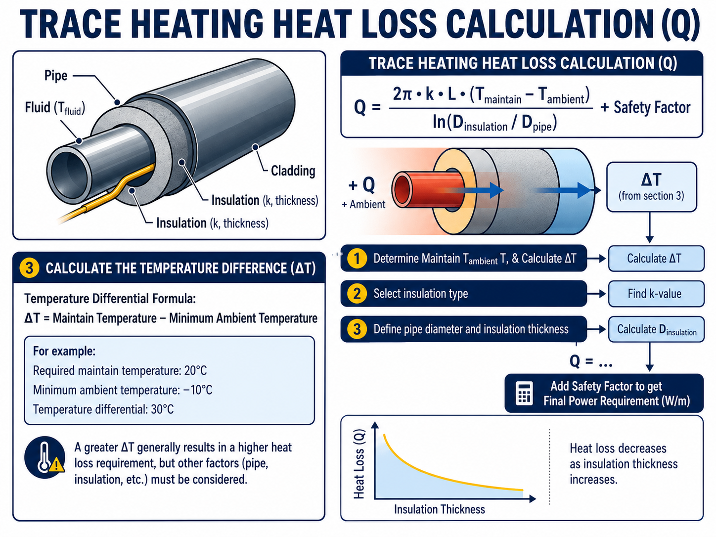
The difference between the required maintain temperature and the minimum ambient temperature is commonly shown as ΔT, or temperature differential.
Temperature Differential Formula
ΔT = Maintain Temperature − Minimum Ambient Temperature
For example:
- Required maintain temperature: 20°C
- Minimum ambient temperature: −10°C
- Temperature differential: 30°C
A greater temperature differential normally results in a greater heat-loss requirement. However, the temperature differential is not the complete heat-loss calculation. Pipe dimensions, insulation, environmental conditions and other design factors must also be considered before the required watts per metre can be established.
4. Record the Pipe Diameter and Material
The outside diameter of the pipe affects the surface area through which heat can escape. A larger pipe will normally lose more heat per metre than a smaller pipe under otherwise identical conditions.
The actual outside diameter should be confirmed rather than estimated from the nominal pipe description, particularly where:
- Non-standard pipework is used
- The line includes different pipe sizes
- Tubing is being heated
- The system contains reducers
- The pipe has an external coating
- Existing insulation is being replaced
The pipe material should also be recorded. Common materials include carbon steel, stainless steel, copper, plastic, composite and glass-lined pipework.
Metal pipes generally distribute heat effectively around their circumference. Plastic and other temperature-sensitive pipes may require additional design measures to spread heat and prevent excessive local surface temperatures.
5. Confirm the Insulation Material and Thickness
Thermal insulation reduces the rate at which heat escapes from the pipe or equipment. It is therefore one of the most influential parts of a heat loss calculation for pipework.
Two items must be confirmed:
- The insulation material
- The insulation thickness
Different insulation materials can have different thermal conductivity values. Two systems with the same pipe diameter and insulation thickness may therefore produce different heat-loss results if the insulation materials differ.
Common insulation materials include:
- Mineral wool
- Glass fibre
- Cellular glass
- Calcium silicate
- Phenolic insulation
- Polyurethane insulation
- Elastomeric insulation
Damaged, compressed or waterlogged insulation may not provide its original thermal performance. Where an existing installation is being upgraded, the insulation condition should be assessed rather than relying only on its original specification.
6. Account for Indoor, Outdoor and Weather Conditions
The same pipe may have a different heat-loss requirement depending on where it is installed.
An indoor pipe in a controlled environment is usually exposed to less severe conditions than pipework installed:
- Outdoors
- On an exposed structure
- On a rooftop
- Offshore
- In a coastal environment
- Within an open-sided building
- In an area subject to high wind speeds
Wind can increase heat transfer from the outer surface of the insulated system. Outdoor calculations may therefore include an adjustment for the specified maximum wind speed and installation conditions.
The insulation should also be protected by suitable weatherproof cladding. Water ingress can reduce insulation performance and increase the heat that the trace heating system must replace.
7. Include Valves, Flanges, Supports and Other Heat Sinks
A straight pipe heat-loss calculation does not always represent the complete system.
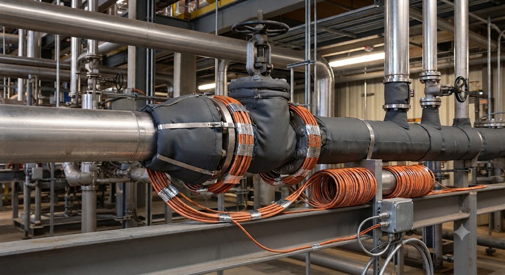
Valves, flanges, pumps, supports and other in-line equipment can have a larger exposed surface area or greater thermal mass than the adjoining pipe. They may therefore require additional heating cable or a specific cable installation arrangement.
- Valves
- Flanges
- Pumps
- Pipe shoes
- Supports and hangers
- Strainers and filters
- Instruments and sample lines
- Branch connections
- Drain points
- Expansion joints
The allowance should be based on the relevant manufacturer’s design method and installation details. A standard percentage should not automatically be applied to every system because the quantity, dimensions and construction of the components can vary considerably.
8. Apply an Appropriate Design Allowance
A trace heating design may include an allowance for uncertainties such as:
- Minor variations in insulation
- Installation tolerances
- Environmental exposure
- Ageing of the system
- Differences between design and actual site conditions
- Small variations in voltage or cable performance
This allowance should be applied using the selected manufacturer’s design methodology or the requirements of the project specification.
Important Design Note
An excessive allowance should not be used as a substitute for accurate design information. Increasing cable output without considering maximum surface temperature, control requirements and electrical loading can result in an inefficient or unsuitable system.
9. Establish the Required Trace Heating Cable Output
Once the adjusted heat loss has been calculated, the result is normally expressed in:
- Watts per metre, or
- Watts per foot
The selected cable must provide sufficient output to compensate for the calculated loss at the required maintain temperature and design conditions.
This is important because the nominal value used in a product name or data sheet may be stated at a particular reference temperature. The actual output available at the required pipe temperature must be checked using the manufacturer’s performance data or design software.
Self-Regulating Heating Cables
Self-regulating heat trace cables vary their output in response to local temperature.
When the surrounding temperature falls, the cable can produce more heat. As the temperature rises, its output reduces. The relevant output at the design maintain temperature must therefore be confirmed from the manufacturer’s output curves or calculation software.
Constant Wattage Heating Cables
Constant wattage heating cables provide a defined output along their heating zones.
Cable output, maximum exposure temperature, circuit length, control requirements and installation arrangement must all be checked against the application.
Mineral-Insulated Heating Cables
Mineral-insulated cables may be selected for high-temperature, high-output or demanding industrial applications.
These systems are normally engineered for the individual application and require careful calculation of cable resistance, circuit length, supply voltage, operating temperature and maximum sheath temperature.
Thorne & Derrick supplies an extensive heat trace cable range for frost protection, process temperature maintenance and industrial heating applications.
Does Pipe Length Affect the Heat Loss Per Metre?
Under uniform conditions, increasing the pipe length does not necessarily change the calculated heat loss per metre.
If every part of a straight pipe has the same diameter, maintain temperature, insulation, ambient temperature and exposure conditions, the heat loss per metre may remain consistent.
However, increasing the pipe length increases:
- Total system heat loss
- Required cable length
- Total electrical load
- Number or length of circuits
- Quantity of connection components
- Potential voltage-drop considerations
- Starting-current requirements
Long pipe runs may also contain changes in pipe diameter, insulation, temperature requirement or area classification. These sections may need to be calculated and circuited separately.
Heat Maintenance Versus Heat-Up Duty
A standard heat-loss calculation usually establishes the power required to maintain a pipe or product at a specified temperature.
It does not necessarily calculate the additional energy required to raise a cold pipe and its contents to that temperature within a defined period.
Where start-up heating is required, additional information may include:
- Initial pipe and product temperature
- Final required temperature
- Volume of the product
- Product density
- Specific heat capacity
- Pipe wall material and thickness
- Required heat-up time
- Additional heat lost during warm-up
A system designed only to replace steady-state heat loss may maintain temperature effectively but take a long time to heat cold process contents.
Heat Loss Calculations for Tanks and Vessels
The same general principles apply when calculating heat loss from tanks, vessels, hoppers and other equipment, but the required inputs are different.
- Total exposed surface area
- Tank shape and dimensions
- Tank material
- Insulation material and thickness
- Minimum ambient temperature
- Required maintain temperature
- Wind speed
- Fluid volume and properties
- Required heat-up time
- Supports, legs and nozzles
- Uninsulated surfaces
Tank and vessel calculations should not be based solely on a pipe heat-loss table. The surface area, construction and start-up requirements can have a substantial influence on the total heating duty.
What Happens After the Heat Loss Has Been Calculated?
The heat-loss result is only one part of the complete electrical heat tracing design.
- Select the heating cable technology
- Confirm cable output at the design temperature
- Determine the number of cable runs
- Calculate the total cable length
- Check maximum circuit lengths
- Establish operating and starting currents
- Select electrical protection
- Select thermostats, controllers and sensors
- Select power connections and termination kits
- Confirm environmental and hazardous-area approvals
- Produce cable schedules and circuit documentation
- Prepare the bill of materials
For hazardous-area applications, the design must also consider the area classification, equipment protection level, temperature classification, maximum cable temperature and certification of the complete system.
Why Use Specialist Heat Trace Design Software?
Simple tables and calculators can provide an initial estimate, but detailed systems should be designed using suitable manufacturer software and verified by a competent trace heating specialist.
Specialist design software can account for:
- Multiple pipe sizes
- Different insulation specifications
- Cable performance at temperature
- Maximum circuit lengths
- Starting and operating currents
- Supply voltage
- Control and monitoring requirements
- Connection components
- Hazardous-area requirements
- Total connected load
- Bills of materials
Manufacturer software is used to match calculated heat loss with a specific cable, connection system and temperature-control arrangement rather than selecting a product solely from its nominal watts-per-metre rating.
Information to Provide for a Trace Heating Calculation
Providing the following information will support an accurate calculation and quotation:
Application Details
- Frost protection or process maintenance
- Description of the product or fluid
- Required maintain temperature
- Minimum ambient temperature
- Maximum process or exposure temperature
- Required heat-up time, where applicable
Pipework Details
- Pipe material
- Outside diameter
- Pipe length
- Number and size of valves
- Number and size of flanges
- Quantity of supports
- Branches, pumps and other equipment
Insulation Details
- Insulation material
- Insulation thickness
- External cladding material
- Condition of existing insulation
Electrical and Site Details
- Available voltage
- Preferred power-supply locations
- Existing circuit limitations
- Control and monitoring requirements
- Indoor or outdoor installation
- Minimum site temperature
- Maximum wind exposure
- Safe-area or hazardous-area classification
- Gas or dust group, where applicable
- Required temperature class
- Corrosive or chemically aggressive conditions
Common Trace Heating Calculation Mistakes
- Using the normal ambient temperature instead of the minimum design temperature
- Confusing process temperature with the required maintain temperature
- Estimating the insulation specification
- Ignoring valves and flanges
- Selecting cable from its nominal output alone
- Failing to check output at the maintain temperature
- Omitting maximum process or steam-cleaning temperatures
- Ignoring circuit-length limitations
- Assuming all pipework has the same diameter and insulation
- Failing to distinguish maintenance duty from heat-up duty
- Treating hazardous-area certification as a cable-only requirement
- Selecting cable before the heat loss is known
Accurate project data helps reduce redesign, avoid unnecessary cable output and improve the reliability of the finished system.
Trace Heating Heat Loss Calculation FAQs
Can Trace Heating Cable Be Selected from the Pipe Diameter Alone?
No. Pipe diameter is only one design input. The maintain temperature, minimum ambient temperature, insulation type, insulation thickness, environmental conditions and application requirements must also be considered.
Does Thicker Insulation Reduce the Required Heating Cable Output?
Generally, yes. Increasing the insulation thickness can reduce heat loss, provided the insulation is correctly selected, installed, dry and protected. The actual reduction will depend on the insulation material, pipe diameter and operating temperatures.
Is the Highest Available Watts-Per-Metre Cable the Safest Choice?
Not necessarily. Excessive output can increase electrical loads, operating costs and surface temperatures. The selected cable should provide sufficient output to compensate for the calculated heat loss while remaining suitable for the pipe material, process temperature, area classification and control system.
Do Valves and Flanges Need Additional Heating Cable?
They commonly require an additional allowance because they can lose more heat than an equivalent length of straight insulated pipe. The cable arrangement and allowance should follow the heating cable manufacturer’s design and installation guidance.
Can a Heat-Loss Calculator Replace a Complete Trace Heating Design?
No. A heat-loss calculator may estimate the required watts per metre, but the complete system design must also consider cable performance, circuit lengths, starting current, electrical protection, controls, accessories, installation conditions and area classification.
Are Additional Design Checks Required for Hazardous Areas?
Yes. The thermal calculation still establishes the required heating output, but hazardous-area systems require additional checks covering equipment certification, area classification, maximum surface temperature, temperature class and the suitability of the heating cable, controls and connection components.
Need a Trace Heating Heat Loss Calculation?
Thorne & Derrick is an experienced supplier of electrical heat tracing systems, heating cables, controls and connection components for commercial, industrial and hazardous-area applications.
- In-house heat-loss calculations
- Trace heating cable selection
- Electrical system design
- Cable and circuit schedules
- Temperature-control specification
- Hazardous-area product selection
- Complete bills of materials
- Technical support for frost protection and process maintenance
Provide the pipework, temperature, insulation and site information to our team, and we can help develop a trace heating system suited to the application.