How to Select Heat Trace Cable for an Industrial Application
Published 08 Sep 2026
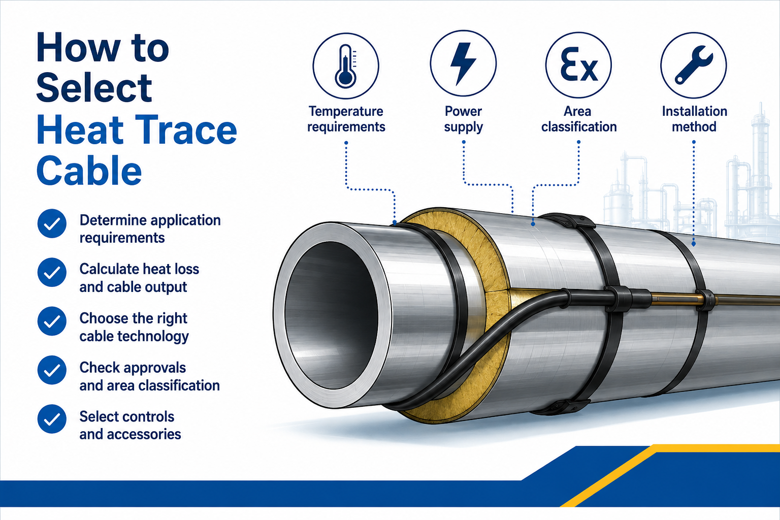
A Step-by-Step Electrical Heat Tracing Cable Selection Guide
Quick Navigation
1. Define the Heating Duty
2. Calculate Heat Loss
3. Confirm Temperature Limits
4. Record Pipe & Equipment Details
5. Choose the Cable Technology
6. Confirm Cable Output
7. Check Electrical Design
8. Assess the Environment
9. Select Controls & Components
10. Verify the Complete System
Cable Selection Table
Design Information Checklist
Common Selection Errors
Frequently Asked Questions
Cable Selection Support
How to Select Heat Trace Cable: Overview
Knowing how to select heat trace cable requires more than choosing a watts-per-metre rating. The cable must compensate for the calculated heat loss while remaining suitable for the maintain temperature, maximum exposure temperature, circuit length, pipe material, environment, controls and area classification.
For readers who need the system fundamentals, see trace heating for frost protection and temperature maintenance. This guide focuses on the specification process rather than providing another general explanation.
The selection outcome should define:
- Heating cable technology and product family
- Required nominal output and performance at temperature
- Number and arrangement of cable runs
- Maximum circuit length and electrical protection
- Power connections, end seals, splices and tees
- Temperature sensors, controllers and limiters
- Safe-area or hazardous-area approvals
- Installation, testing and maintenance requirements
1. Define the Heating Duty
Begin by establishing what the system must achieve.
| Duty | Primary Objective | Key Design Question |
|---|---|---|
| Frost protection | Keep water or process fluid safely above its freezing point | What is the lowest design ambient temperature and required protective margin? |
| Process temperature maintenance | Keep a product pumpable, flowable or within a process range | What maintain temperature is required for viscosity, crystallisation or production? |
| Hot-water maintenance | Maintain distribution temperature while limiting heat loss | What water temperature and circulation strategy must be maintained? |
| Controlled heat-up | Raise a pipe, vessel or product temperature within a defined period | What energy is required for the mass, heat capacity and target heat-up time? |
| Winterisation | Protect multiple exposed plant systems during cold weather | Which lines and equipment are critical and how are circuits grouped and monitored? |
Do not assume that normal operating temperature is the same as the minimum temperature the trace heating system must maintain.
2. Calculate the Heat Loss
A trace heating heat loss calculation establishes the heating output required to replace the heat escaping through the insulation under the design conditions.
- Required maintain temperature
- Minimum ambient temperature
- Pipe diameter and material
- Insulation type and thickness
- Indoor, outdoor and wind exposure
- Valves, flanges, supports and other heat sinks
- Design allowance and any heat-up requirement
Do Not Select from Pipe Size Alone
Two pipes of the same diameter can require different cable outputs because maintain temperature, ambient conditions, insulation and exposure differ. Cable selection should follow the thermal calculation.
3. Confirm Every Relevant Temperature Limit
The cable and every component must be suitable for both normal operation and credible exposure conditions.
Record these temperatures:
- Required maintain temperature
- Minimum ambient temperature
- Maximum normal process temperature
- Maximum intermittent or exposure temperature
- Steam-cleaning, purging or sterilisation temperature
- Minimum installation temperature
- Maximum permitted pipe or equipment surface temperature
- Required hazardous-area temperature class, where applicable
4. Record the Pipe, Vessel or Equipment Details
Cable performance and installation method depend on the surface being heated.
- Pipe outside diameter, length and material
- Tank or vessel dimensions and shape
- Number and size of valves, flanges and pumps
- Pipe supports, shoes and instruments
- Plastic or temperature-sensitive surfaces
- Removable sections and maintenance access
- Available straight runs and cable-routing restrictions
- Insulation and external cladding specification
Plastic pipework may require output limitations, heat-spreading foil or a specific installation method to prevent local overheating.
5. Choose the Heat Trace Cable Technology
| Cable Technology | Common Selection Reasons | Main Design Considerations |
|---|---|---|
| Self-regulating | Variable ambient conditions, frost protection, complex fittings and field cut-to-length installation | Output at maintain temperature, start-up current, maximum circuit length and temperature limits |
| Constant wattage / parallel resistance | Defined output, controlled process duties and specialist cable constructions | Control method, zone spacing, cable contact, exposure temperature and maximum circuit length |
| Series resistance | Long circuits and engineered industrial duties | Fixed designed length, voltage, conductor resistance, output and termination arrangement |
| Mineral-insulated | High temperatures, high output, severe environments and engineered long circuits | Sheath alloy, resistance design, sheath temperature, cold leads, joints and specialist installation |
Use the detailed self-regulating vs constant wattage trace heating comparison and the guide explaining when mineral-insulated heat trace cable is required to narrow the technology choice.
6. Confirm Cable Output at the Design Temperature
Nominal cable output is often quoted at a reference temperature. The available output at the actual maintain temperature can differ.
- Use manufacturer power-output curves or approved design software
- Apply the correct pipe-material and installation correction factors
- Check whether one or multiple cable runs are required
- Confirm cable spacing around fittings and local heat sinks
- Verify maximum sheath or surface temperature
- Avoid unnecessary oversizing that increases electrical load and control cycling
7. Check Voltage, Circuit Length and Electrical Protection
Cable selection must be coordinated with the available electrical supply and the proposed circuit architecture.
| Electrical Input | Why It Matters |
|---|---|
| Supply voltage | Only cable variants designed for the available voltage should be selected |
| Maximum circuit length | Affected by cable type, output, voltage, breaker size and minimum start-up temperature |
| Start-up current | Self-regulating cable can draw increased current when cold |
| Operating current | Determines connected load, switching and distribution requirements |
| Circuit protection | Must match manufacturer data, wiring rules and the site design |
| Earth-fault protection | Required arrangement depends on the electrical and system standard |
| Power-feed locations | Can reduce circuit length or determine single- and dual-end supply arrangements |
8. Assess Environmental and Hazardous-Area Conditions
The outer jacket, braid, sheath, connection kits and enclosures must be suitable for the installation environment.
- Indoor, outdoor, offshore or buried location
- Moisture, UV and weather exposure
- Chemical, oil, solvent or corrosive exposure
- Mechanical impact and abrasion
- Food, hygiene or washdown requirements
- Safe-area or hazardous-area classification
- Gas group, dust group and temperature class
- Ambient-temperature range
For explosive atmospheres, use a complete ATEX trace heating system selected for the area classification and certification conditions.
9. Select Controls, Sensors and Connection Components
The heating cable is only one part of the circuit. A complete design may include:
System components:
- Power connection and junction box
- End seal
- Splice and tee connection kits
- Temperature sensor
- Ambient- or pipe-sensing thermostat
- Electronic controller and alarm system
- Independent temperature limiter
- Distribution panel and protective devices
- Fixing tape, support brackets and warning labels
- Thermal insulation and weatherproof cladding
Select controls for the duty rather than treating them as optional accessories. Hazardous-area options include digital heat trace thermostats and temperature limiters.
10. Verify the Complete Electrical Heat Tracing System
Before ordering, verify that the selected products form a compatible and documented system.
- Confirm the heat-loss and cable-output calculation
- Check cable temperature, voltage and circuit-length limits
- Confirm the number and position of power feeds
- Select manufacturer-approved power connections and terminations
- Verify controller, sensor and limiter ranges
- Confirm the enclosure and component environmental ratings
- Check hazardous-area certificates and conditions of use
- Prepare cable schedules, circuit drawings and a bill of materials
- Define installation and commissioning tests
- Obtain technical approval for critical or complex systems
Quick Heat Trace Cable Selection Table
| Application Requirement | Technology to Investigate First | Further Check |
|---|---|---|
| Basic water-pipe frost protection | Self-regulating | Pipe material, minimum ambient, insulation and circuit length |
| Variable ambient conditions | Self-regulating | Output at maintain temperature and start-up current |
| Defined process output | Constant wattage or resistance | Control, exposure temperature and cable spacing |
| Long industrial pipeline | Series resistance, MI or suitable parallel cable | Voltage, power feeds, circuit length and control architecture |
| Very high temperature | MI or specialist resistance cable | Sheath material, joints, cold leads and temperature limiting |
| Hazardous area | Certified cable technology suited to the duty | Complete system certification, temperature class and accessories |
| Plastic pipe | Approved lower-output cable and installation method | Maximum pipe temperature and heat-spreading requirements |
Heat Trace Cable Design Information Checklist
Application information to provide:
- Purpose of the system
- Fluid or product
- Required maintain temperature
- Minimum ambient temperature
- Maximum process and exposure temperatures
- Pipe or equipment material and dimensions
- Pipe length and quantity of fittings
- Insulation material and thickness
- Available voltage
- Indoor, outdoor or hazardous-area location
- Required heat-up time
- Preferred control, monitoring and alarm functions
Once these details are confirmed, explore the complete heat trace cable range or request an engineered specification.
Common Heat Trace Cable Selection Errors
- Choosing cable from pipe diameter or nominal wattage alone
- Using average ambient temperature instead of the minimum design temperature
- Ignoring maximum exposure or cleaning temperature
- Assuming self-regulating cable never requires controls
- Cutting constant wattage or series cable outside its permitted method
- Failing to include valves, flanges and supports
- Ignoring start-up current and maximum circuit length
- Specifying a hazardous-area cable without compatible certified components
- Treating thermal insulation as outside the system design
- Selecting products before the heat loss and operating duty are known
Heat Trace Cable Selection FAQs
What Is the First Step When Selecting Heat Trace Cable?
Define the duty and calculate the heat loss using the required maintain temperature, minimum ambient temperature, pipe dimensions and insulation specification.
Can Cable Be Selected Using Watts Per Metre Alone?
No. The output must be checked at the design temperature and coordinated with temperature ratings, voltage, circuit length, controls, pipe material and environmental approvals.
Which Cable Is Best for Frost Protection?
Self-regulating cable is frequently considered, but the final selection depends on heat loss, pipe material, insulation, voltage, circuit length and location.
Which Cable Is Used for High-Temperature Applications?
Mineral-insulated or specialist resistance cables may be required. Selection depends on maintain and exposure temperatures, output, circuit length, sheath material and control requirements.
Does Hazardous-Area Cable Need Special Accessories?
Yes. Power connections, end seals, junction boxes, controls, glands and other components must be suitable for the cable, area classification and certification conditions.
Should Heat Trace Cable Be Oversized for Safety?
A justified design allowance may be applied, but excessive output can increase load, energy use and surface temperature. Accurate data and appropriate control are safer than arbitrary oversizing.
Need Help Selecting Heat Trace Cable?
Thorne & Derrick provides technical support from heat-loss calculation through cable, control and component specification.
- Frost-protection cable selection
- Process temperature-maintenance design
- Self-regulating, constant wattage and MI technology
- Circuit length and electrical load review
- Controllers, sensors and limiters
- ATEX and hazardous-area system specification