Electrical Heat Tracing System Components Explained
Published 29 Sep 2026
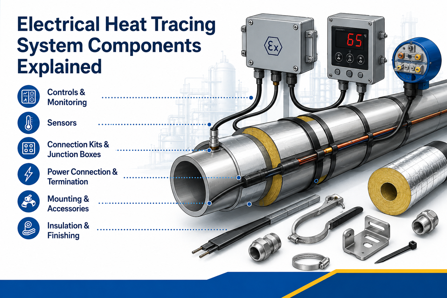
The Cable, Controls, Connections and Insulation That Form a Complete System
Quick Navigation
Heating Cable
Power Connections
End Seals, Splices & Tees
Junction Boxes & Cable Entries
Temperature Sensors
Thermostats & Controllers
Temperature Limiters
Distribution & Circuit Protection
Monitoring & Alarms
Fixing & Mechanical Accessories
Insulation, Cladding & Labels
Documentation & Identification
Component Compatibility
Frequently Asked Questions
System Component Support
Electrical Heat Tracing System Components: Overview
Electrical heat tracing system components work together to supply, control, monitor and contain the heating circuit. A complete system is not simply a heating cable attached to a pipe.
For the general operating principle, read electrical heat tracing explained. This article concentrates on the role and selection of each physical system component.
A complete system may include:
- Heating cable or engineered trace heater
- Power connection
- End seal
- Splice and tee components
- Junction boxes and cable glands
- Temperature sensors
- Thermostats, controllers and limiters
- Electrical distribution and protective devices
- Alarm and monitoring equipment
- Fixing materials and mechanical supports
- Thermal insulation and weatherproof cladding
- Warning labels, drawings and circuit documentation
1. Heating Cable or Trace Heater
The heating cable converts electrical energy into heat and transfers it into the pipe, vessel or equipment surface.
| Cable Technology | Typical Role |
|---|---|
| Self-regulating | Local output response to temperature; common for frost protection and process maintenance |
| Constant wattage / parallel resistance | Defined output along repeated heating zones |
| Series resistance | Engineered resistance and length for industrial or long-line duties |
| Mineral-insulated | High-temperature, high-output and severe-environment applications |
Cable technology should be selected using the heat trace cable selection process, not treated as an interchangeable component.
2. Power Connection
The power connection links the heating cable to the electrical supply, often through a junction box or integrated connection enclosure.
- Provides controlled separation and termination of heating conductors
- Maintains insulation and environmental sealing
- Connects the earth braid or metal sheath correctly
- Supports cable strain relief
- May provide a pipe-mounted junction-box arrangement
- Must be compatible with the specific cable construction
Use Approved Connection Systems
A power connection is not a generic cable joint. Use the cable manufacturer’s specified components and preparation method. Improvised substitutions can introduce overheating, moisture ingress, short circuits or loss of hazardous-area compliance.
3. End Seals, Splices and Tee Connections
End Seal
The end seal electrically insulates and environmentally seals the remote end of a parallel heating cable. It must prevent moisture reaching the conductive core or bus wires.
Splice
An approved splice joins compatible heating-cable sections where the system design permits. It must preserve electrical, environmental and mechanical integrity.
Tee Connection
A tee component supports a designed branch circuit. Branching changes cable length, current and protection requirements, so it must be included in the circuit design.
End-of-line indication can support visual system checks. See the Eltherm end-of-line termination and monitoring devices.
4. Junction Boxes, Glands and Cable Entries
Junction boxes provide accessible electrical connection points for power, control, branching or monitoring equipment.
Selection factors:
- Safe-area or hazardous-area certification
- Ingress protection and outdoor exposure
- Corrosion and chemical resistance
- Operating and ambient temperatures
- Number and size of cable entries
- Terminal capacity and current rating
- Earthing and bonding requirements
- Mounting position and maintenance access
Cable glands, grommets and seals must match the enclosure, cable and certification arrangement. Maintain the specified ingress protection and strain relief.
5. Temperature Sensors
Temperature sensors provide the measurement used by a thermostat, controller, limiter or monitoring system.
| Sensor Arrangement | Typical Use | Key Consideration |
|---|---|---|
| Ambient sensing | Group frost-protection control | Sensor must represent the coldest relevant ambient condition without false influences |
| Pipe-surface sensing | Direct pipe temperature maintenance | Position and attachment must represent the controlled surface temperature |
| Product or process sensing | Process-critical temperature control | Sensor type and location must match the process design |
| Dual sensing | Independent control and high-temperature limit | Control and safety functions should remain appropriately separated |
Poor sensor placement can cause underheating, overheating or excessive cycling even when the heating cable is operating correctly.
6. Thermostats and Electronic Controllers
Controllers switch or regulate the heating circuit to maintain the required temperature and reduce unnecessary operation.
- Mechanical ambient-sensing thermostat
- Mechanical pipe-sensing thermostat
- Digital single-circuit controller
- Multi-circuit control panel
- Proportional or modulating controller
- Controller with alarms, data logging or communications
Available options include capillary heat trace thermostats and hazardous-area digital temperature controllers.
7. Independent Temperature Limiters
A temperature limiter disconnects the heating circuit if a defined maximum temperature is exceeded. It is distinct from the normal process controller.
- Protects temperature-sensitive product or equipment
- Supports maximum sheath or surface-temperature control
- Can be required by a hazardous-area temperature-limitation method
- May use an independent sensor and manual reset
- Should be set and positioned according to the system design
See the Eltherm hazardous-area trace heating limiter for an example of this component type.
8. Electrical Distribution and Circuit Protection
The distribution system supplies and protects each heating circuit.
Electrical components can include:
- Distribution board or heat-tracing panel
- Circuit breaker or fuse
- Earth-fault or residual-current protection
- Contactor or solid-state switching device
- Isolation device
- Control transformer or power transformer where required
- Status indication and local switches
- Terminals, busbars and protective earthing
Protection must account for operating current, self-regulating cable start-up current, conductor size, maximum circuit length, switching duty and the applicable electrical design requirements.
9. Monitoring, Alarms and Communications
Monitoring equipment provides visibility beyond simple on/off control.
- Low- and high-temperature alarms
- Sensor-failure alarms
- Circuit current monitoring
- Earth-leakage monitoring
- Loss-of-power indication
- End-of-line indication
- Remote communications and supervisory software
- Event logs and historical performance data
Monitoring is particularly valuable for large winterisation systems, critical process lines and remote or hazardous installations where a silent failure may not be noticed quickly.
10. Fixing and Mechanical Installation Accessories
Fixing products secure the cable in the designed position and support effective heat transfer.
| Accessory | Purpose |
|---|---|
| Fixing tape | Secures cable to the pipe using a material approved for the temperature and surface |
| Heat-transfer foil | Improves heat distribution, especially on plastic or temperature-sensitive surfaces |
| Pipe straps and brackets | Support connection enclosures and components without damaging the cable |
| Spacing guides | Maintain designed separation between parallel cable runs |
| Insulation entry kits | Protect cable where it passes through external cladding |
| Mechanical guards | Protect cable from impact or abrasion at vulnerable locations |
11. Thermal Insulation, Cladding and Warning Labels
Thermal insulation limits heat loss and is essential to the designed performance of most trace heating systems.
- Insulation material and thickness must match the heat-loss calculation
- Weatherproof cladding prevents water ingress and physical damage
- Removable jackets maintain insulation around valves and equipment needing access
- Entry seals protect cable and sensor penetrations
- Warning labels identify electrically traced pipework and should remain visible
If insulation specification changes, review the trace heating heat-loss calculation before assuming the original cable remains suitable.
12. Identification and System Documentation
Documentation is a functional system component because it enables safe isolation, testing, repair and future modification.
Recommended documents:
- Heat-loss and cable-selection calculations
- Cable and circuit schedule
- Pipe and instrument drawings showing traced lines
- Power-feed, splice, tee and end-seal locations
- Controller, sensor and limiter settings
- Hazardous-area certificates and conditions of use
- Installation and test records
- Commissioning voltage, resistance, current and temperature data
- Maintenance and fault history
Why Component Compatibility Matters
Heating cable, connection kits, controls, sensors and enclosures should be selected as a coordinated system.
- Power and end components must fit the cable dimensions and conductor arrangement
- Materials must suit the operating and exposure temperature
- Ingress protection depends on correct component assembly
- Controller and sensor ranges must cover the process duty
- Circuit protection must match cable current and start-up behaviour
- Hazardous-area certification may depend on specified components and installation conditions
After installation, use a documented trace heating testing and maintenance programme to verify the continued condition of the complete system.
Electrical Heat Tracing System Components FAQs
What Components Are Needed for a Basic Trace Heating Circuit?
A basic parallel-cable circuit normally requires the heating cable, a power connection, an end seal, electrical protection, suitable control where required, fixing materials and thermal insulation. The exact system depends on the application.
Are Trace Heating Connection Kits Universal?
No. Connection kits must be approved for the specific cable family, dimensions, temperature range, environment and area classification.
What Is the Difference Between a Controller and a Limiter?
A controller maintains the normal process or pipe temperature. A limiter independently disconnects the circuit if a maximum permitted temperature is exceeded.
Does Self-Regulating Cable Still Need a Temperature Sensor?
It may. Sensors and controls can be required for process accuracy, energy management, alarms or hazardous-area temperature limitation.
Why Is Thermal Insulation Considered a System Component?
The cable is selected to replace the heat lost through the insulation. Missing, wet or changed insulation alters the duty and can prevent the system maintaining temperature.
Which Components Require Hazardous-Area Certification?
All equipment installed within or associated with the classified location must be assessed for the area and system design, including connection kits, enclosures, glands, controls, sensors and heating cable.
Need Help Specifying Trace Heating Components?
Thorne & Derrick supplies heating cables, connection systems, controls, sensors and certified components for complete electrical heat tracing systems.
- Cable and connection-kit compatibility
- Power connections, splices, tees and end seals
- Thermostats, controllers and temperature limiters
- Junction boxes and hazardous-area enclosures
- Monitoring and end-of-line indication
- Complete bills of materials and system design