Why Is My Heat Trace Cable Not Heating? Common Faults Explained
Published 02 Nov 2026
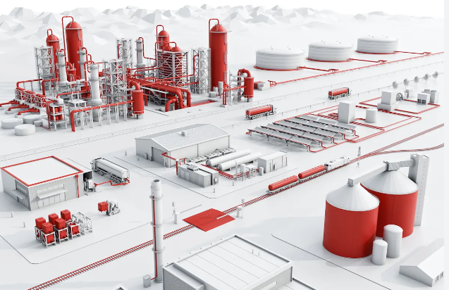
Heat trace cable not heating? When an electric heat tracing system stops maintaining the required pipe or process temperature, the cause is not always a failed heating cable. Common problems include electrical supply faults, incorrect thermostat settings, damaged cable connections, deteriorated heating cable, wet thermal insulation and incorrect temperature sensor positioning.
Heat tracing systems are widely used to protect water pipes against freezing and maintain process temperatures across industrial pipework, tanks, valves and equipment. When heating performance deteriorates, the consequences may include frozen lines, reduced process flow, blocked pipework or interrupted production.
However, a pipe remaining cold does not automatically mean the heating cable has failed. The system may be intentionally switched off by its thermostat, operating at reduced output because of the pipe temperature or losing heat faster than the installed cable can replace it.
This technical guide explains why heat trace cables stop heating, how common symptoms relate to electrical and thermal faults, and what qualified personnel should consider when inspecting a heat tracing system.
Thorne & Derrick supply industrial heat trace cables and complete trace heating systems for frost protection, temperature maintenance and process heating applications.
Quick Answer: Why Is My Heat Trace Cable Not Heating?
Heat trace cable may stop heating because the electrical supply is interrupted, a thermostat or controller is not calling for heat, a cable or connection is damaged, or the system has insufficient output to overcome heat loss.
Other possible causes include incorrectly positioned temperature sensors, moisture-damaged terminations, wet thermal insulation and circuit protection operating because of an electrical fault.
For self-regulating heat trace cable, reduced heat output at warmer temperatures can be normal. Its output varies with local cable temperature, so a cable that does not feel particularly hot may still be operating as intended.
Fault diagnosis should distinguish between no electrical heating, insufficient heating and normal controlled operation.
Common Heat Tracing Faults & Symptoms
An electric trace heating system consists of more than the heating cable itself. Power connections, end terminations, thermostats, sensors, circuit protection, insulation and weatherproofing all affect performance.
Faults in these components can create similar symptoms, making it important to identify the specific operating condition before replacing equipment.
How Do Different Heat Tracing Faults Present?
These symptoms indicate possible fault categories rather than confirming a diagnosis. Multiple defects can occur within the same heating circuit.
1. Power Supply & Electrical Protection Faults
One of the first areas to investigate when trace heating is not working is whether the heating circuit is receiving the electrical supply required by the design.
The power supply may be interrupted at the distribution board, a local isolator, an electrical connection or the control system.
Common Electrical Supply Problems
- Open circuit breaker or protective device: Electrical protection may have operated following a fault.
- Isolated power supply: The heating circuit may be intentionally switched off for maintenance.
- Disconnected or damaged wiring: Supply conductors or connection components may be compromised.
- Incorrect supply voltage: The installed cable may not be compatible with the available voltage or may receive insufficient supply.
- Control circuit not energising: A thermostat, relay or controller may be preventing power from reaching the heater.
Electrical supply faults can prevent a functioning heating cable from producing heat.
Why the Circuit Breaker Must Not Simply Be Reset
A breaker or earth-fault protective device that has operated may indicate a serious fault.
Repeated resetting without identifying the cause can expose equipment and personnel to additional electrical hazards.
Qualified personnel should investigate the reason for protective device operation using the applicable electrical safety procedures.
2. Thermostat & Temperature Sensor Problems
Heat tracing thermostats and temperature controllers regulate when electrical heating is required. A system may remain cold because the controller is operating correctly and the measured temperature is already above its switching threshold.
However, incorrect settings or a defective temperature measurement arrangement can prevent the heating system from operating when needed.
Incorrect Thermostat Setpoint
A frost protection thermostat may only activate the heating circuit when its measured temperature falls below a specified threshold.
For example, some frost protection systems are configured to operate at low ambient temperatures rather than continuously.
If the measured temperature is above the controller’s setpoint, the heating circuit may remain switched off even when the heating cable is electrically sound.
Temperature Sensor Positioning
The position of a temperature sensor affects the temperature reported to the controller.
Potential problems include:
- A sensor incorrectly positioned away from the intended measurement point.
- A pipe-mounted sensor losing thermal contact with the pipe.
- Inadequate insulation around the measurement location.
- A sensor installed where it does not represent the required process temperature.
- Damaged sensor wiring or incorrect controller configuration.
These conditions can cause the controller to switch incorrectly, operate at unexpected times or produce unreliable temperature regulation.
Controller Faults and Alarm Conditions
Electronic controllers may display fault codes or alarm conditions associated with sensor input, power supply or heating circuit operation.
These should be interpreted using the specific controller documentation.
Changing settings without understanding the system design can compromise frost protection, process temperature maintenance or temperature limiting.
3. Damaged Heat Trace Cable & Electrical Connections
Physical damage to heat trace cable can prevent it from heating correctly, cause intermittent operation or create an electrical insulation fault.
Damage may occur during initial installation, subsequent maintenance activities or long-term service.
Where Does Heat Trace Cable Become Damaged?
Potential damage locations include:
- Valves and flanges: Cable disturbed during mechanical maintenance or component replacement.
- Pipe supports: Local mechanical pressure or abrasion affecting the cable.
- Junction boxes: Incorrectly assembled or deteriorated electrical connections.
- End seals: Compromised termination integrity or moisture ingress.
- Insulation removal points: Cable accidentally cut, crushed or damaged during maintenance.
- High-temperature areas: Exposure outside the permitted cable temperature rating.
Why Cable Terminations Matter
Self-regulating heating cables commonly use parallel bus conductors and a temperature-responsive heating matrix.
Approved power connection kits, splices and end seals are required to maintain the electrical and environmental integrity of the system.
Incorrect connection assembly may result in poor electrical continuity, moisture ingress or faults between conductive components.
Can a Damaged Heat Trace Cable Be Repaired?
Some heating cable systems permit repairs using manufacturer-approved splice kits and procedures, subject to the cable type, installation environment and certification requirements.
Other damage may require replacement of the affected section or complete circuit.
Never assume damaged heating cable can be repaired using conventional electrical tape or an ordinary connector. The repair method must be approved for the specific system.
Thorne & Derrick supply heat tracing cables, connection accessories and system components for industrial heating applications.
4. Is Self-Regulating Heat Trace Cable Supposed to Feel Hot?
A common misconception is that a functioning heat trace cable must always feel noticeably hot.
Self-regulating heat trace cable adjusts its electrical heat output according to the local temperature of the heating element.
As the cable becomes warmer, its electrical resistance increases and its heat output decreases. At lower temperatures, its heat output increases within the product’s specified performance characteristics.
This means a functioning cable may produce relatively little heat when the pipe or surrounding environment is warm.
Self-Regulating Does Not Mean Self-Switching
Self-regulating technology changes the heating cable’s output. It does not necessarily switch the electrical supply completely off or replace the need for suitable temperature controls.
Some applications require thermostats, controllers or independent temperature limiting according to the design and safety requirements.
Why Touching the Cable Is Not a Reliable Test
The perceived temperature of a heating cable depends on its output, pipe temperature, surrounding conditions and heat transfer.
A cable may be operating without feeling particularly hot. Conversely, exposed or faulted electrical heating equipment may present a burn or electrical hazard.
Do not remove insulation or touch exposed energised heating cable to determine whether it is working. Competent personnel should use suitable measurements and the manufacturer-approved testing procedure.
For further technical information, explore Eltherm self-regulating heat tracing cables.
5. Thermal Insulation & Heat Loss Problems
Sometimes the heat trace cable is operating correctly, but the pipe or process equipment is still failing to maintain the required temperature.
In these cases, the problem may be excessive heat loss rather than an electrical heating failure.
A correctly designed trace heating system supplies sufficient heat to compensate for losses under the specified operating conditions.
Where insulation becomes damaged, wet or incomplete, those losses can increase substantially.
Wet or Missing Insulation
Thermal insulation that becomes saturated with moisture may perform significantly worse than dry insulation.
Damaged cladding or inadequate weatherproofing can allow moisture to enter insulation around pipes and fittings.
The heating cable may then struggle to maintain the target temperature despite functioning electrically.
Insufficient Heating Around Valves & Flanges
Valves, flanges, pipe supports and other components can create additional heat losses compared with a simple straight pipe.
If the heating arrangement does not compensate for these locations, localised cold areas may develop.
Operating Conditions Have Changed
A system designed for one set of conditions may no longer perform adequately following changes to:
- Minimum ambient temperature or outdoor exposure.
- Required process maintenance temperature.
- Pipe insulation thickness or material.
- Valve, pump or equipment configuration.
- Pipework layout or circuit length.
- Process conditions and temperature requirements.
Where system performance has deteriorated, the original design documentation should be compared with current operating conditions.
If the original system has insufficient heating capacity, the solution may require redesign rather than replacing the existing cable with an apparently higher-output product.
6. Why Does My Heat Tracing Circuit Breaker Keep Tripping?
A heat tracing circuit breaker or earth-fault protection device can operate for several reasons.
The underlying problem may involve the electrical supply, cable insulation, connections, protective device selection or the circuit’s electrical loading.
Possible Causes of Circuit Breaker Tripping
- Cold start-up current: Some self-regulating heating cables draw greater current when first energised at low temperatures.
- Excessive circuit length: The installed heating circuit may exceed the permitted design limits for its cable type and protective device.
- Short circuit: Damaged conductors or incorrectly assembled connections may create a fault.
- Earth leakage: Damaged electrical insulation or moisture ingress may cause protective devices to operate.
- Incorrect protective device selection: The protection arrangement may be unsuitable for the cable and circuit design.
Some self-regulating cable manufacturers provide maximum circuit lengths based on start-up temperature, nominal supply voltage and protective device characteristics.
For example, the Eltherm ELSR-N heating cable range includes circuit-length information for different switch-on temperatures and protective device ratings.
These values are product-specific and should not be applied universally to other heating cables.
7. How Are Heat Tracing Faults Investigated?
Effective heat trace troubleshooting begins by establishing whether the problem is electrical, control-related or thermal.
The investigation should use the available installation drawings, cable schedules, commissioning records, controller information and manufacturer instructions.
Initial System Assessment
A competent technician may first review:
- The intended heating duty and required maintain temperature.
- Controller readings, setpoints and alarm information.
- Recorded circuit faults and protective device operation.
- Recent maintenance or mechanical work on the pipework.
- Evidence of damaged or wet insulation and cladding.
- Changes to operating conditions since commissioning.
Electrical Testing
Depending on the cable type and approved procedure, specialist electrical checks may include:
- Supply and control circuit verification: Establishing whether the correct electrical conditions are present.
- Insulation resistance testing: Investigating insulation condition and possible faults between conductive components.
- Continuity or circuit resistance testing: Checking suitable cable technologies and connection arrangements.
- Current and power measurements: Comparing observed heating circuit performance with applicable manufacturer data and design records.
- Fault location procedures: Identifying suspected damaged cable sections or connection components.
Test methods and acceptance criteria vary according to the heating cable construction and associated equipment. Self-regulating, constant wattage, series resistance and mineral-insulated cable systems must not all be tested or interpreted in the same way.
For example, resistance measurements on a self-regulating heating cable cannot necessarily be interpreted in the same manner as fixed-resistance heating elements.
Physical Inspection
Where safe and authorised, a physical inspection may identify damaged cable jackets, compromised terminations, defective connections or moisture ingress.
Insulation removal, circuit disconnection and testing must be planned to avoid introducing additional damage or exposing personnel to electrical and process hazards.
Hazardous Area Trace Heating
Additional precautions apply where heat tracing equipment is installed in ATEX or IECEx hazardous areas.
Equipment certification, permitted connection systems, temperature limits and the site’s hazardous-area safety controls must be maintained during inspection and repair.
Testing that could introduce an ignition source must not be undertaken in a potentially explosive atmosphere without the required safe working arrangements.
No single test proves that every part of a heat tracing system is functioning correctly. Findings should be assessed together with the original design and relevant manufacturer documentation.
8. How Can Heat Tracing Failures Be Prevented?
Preventing heat tracing problems requires attention to the complete installed system, not only the condition of the heating cable.
Inspection and maintenance are particularly important for outdoor industrial pipework, process installations and systems exposed to seasonal weather conditions.
Before Winter or Critical Operation
- Review the required heating duty and expected operating conditions.
- Check controller status, temperature setpoints and relevant alarms.
- Inspect accessible insulation and weatherproof cladding for damage.
- Review previous electrical test and inspection results.
- Confirm the required maintenance has been completed by competent personnel.
Following Pipework Maintenance
- Check whether heating cable has been disturbed or damaged.
- Verify that valves, flanges and fittings have been correctly reinstated.
- Ensure removed insulation and cladding have been replaced appropriately.
- Complete the required electrical checks before returning the system to service.
Long-Term Reliability
- Keep accurate cable circuit and installation records.
- Retain manufacturer instructions and commissioning test results.
- Review repeated protective device trips and controller alarms.
- Monitor changes to process temperatures and operating conditions.
- Use suitable approved components for repairs and replacements.
For critical installations, planned monitoring and maintenance can help identify deterioration before process temperatures fall below acceptable limits.
9. Related Heat Tracing Products & Equipment
Resolving a heat tracing problem may require replacement heating cable, suitably approved connection components, temperature control equipment or a review of the original system design.
Thorne & Derrick supply specialist heating equipment for industrial frost protection, process temperature maintenance and hazardous-area applications.
Heat Trace Cable Not Heating – Frequently Asked Questions
Q: Why is my heat trace cable not getting hot?
A: Possible causes include an interrupted supply, a thermostat that is not calling for heat, damaged cable connections or a fault within the heating circuit. A self-regulating cable may also produce relatively little heat when its local temperature is already high. The cause should be established through appropriate system checks.
Q: How do you know if heat trace cable is working?
A: Qualified personnel can assess the system using controller status, actual pipe temperatures and appropriate electrical measurements compared with the manufacturer’s data and installation records. Feeling the cable by hand is not a reliable or safe method.
Q: Why does my self-regulating heat trace cable feel cold?
A: Self-regulating cable reduces its heat output as its local temperature rises. A cable that feels cool may therefore be operating normally, particularly where little heating is required. Its actual performance should be verified using the appropriate testing method.
Q: Why does my heat trace breaker keep tripping?
A: Causes may include excessive start-up current, incorrect protective device selection, a short circuit, moisture ingress, damaged cable insulation or an earth-fault condition. Do not repeatedly reset the circuit without a competent electrical investigation.
Q: Can heat tracing work but the pipe still freeze?
A: Yes. If the heat loss exceeds the available heating output, the pipe temperature may fall despite the cable operating. Wet insulation, insufficient cable coverage, incorrect design assumptions or changed operating conditions can contribute to this problem.
Q: Can a damaged heat trace cable be repaired?
A: Some heating cable systems permit repairs using approved splice kits and procedures. Suitability depends on the cable technology, extent of damage, manufacturer requirements and installation environment. Other situations require replacement of the damaged cable section.
Q: Does self-regulating heat trace cable need a thermostat?
A: Self-regulating cable adjusts its heat output according to temperature, but many applications still require thermostatic control, monitoring or temperature limiting. The requirements depend on the system design and applicable safety conditions.
Q: What maintenance does heat tracing require?
A: Appropriate maintenance may include electrical testing, controller and sensor checks, inspection of terminations, review of circuit protection, assessment of insulation condition and inspection following pipework maintenance. The work and frequency must follow the applicable equipment and site requirements.
Conclusion: Why Heat Trace Cables Stop Heating
Heat trace cable not heating does not necessarily mean that the heating cable itself has failed. Electrical supply interruptions, thermostat operation, damaged connections, insulation deterioration and excessive heat loss can all affect the performance of an installed trace heating system.
Effective troubleshooting requires an understanding of the complete system, including its electrical protection, temperature controls, heating cable technology, thermal insulation and actual operating conditions.
For critical frost protection and process temperature maintenance applications, qualified inspection, accurate installation records and appropriate maintenance can help identify problems before they result in frozen pipework or process disruption.
Thorne & Derrick supply self-regulating, constant wattage and specialist industrial heat tracing equipment, supported by technical product selection assistance for new installations, replacement circuits and process heating applications.
Technical and safety note: This guide provides general fault-identification information and is not a procedure for testing or repairing energised heating equipment. Fault diagnosis, circuit isolation, electrical testing and repairs must be undertaken by competent authorised personnel following the manufacturer instructions, applicable standards, site procedures and hazardous-area safety requirements where relevant.