Self Regulating Heat Tracing | Eltherm ELSR-N ATEX Heat Tracing Cable (Up to 80 Degrees Celsius)
")
Thorne & Derrick | Distributed from Stock | UK & Export Sales | Customer Service Excellence | ATEX Compliant Solutions
Self Regulating Heat tracing
ATEX Heat Tracing Cable | Eltherm ELSR-N
Eltherm ELSR-N is a versatile self-regulating heat tracing cable that provides process temperature maintenance and frost protection to pipework, instrument lines, tanks and drums up to 80° Celsius – with IECEx and ATEX Certification Eltherm ELSR-N heat tracing cables are suitable for Zone 1 and Zone 2 hazardous areas.
The self-regulating technology allows the heating cable to increase or decrease its heat output based on the ambient temperature, providing energy-efficient operation and preventing overheating. ELSR-N is suitable for use in various industrial applications where maintaining consistent temperatures is critical for process integrity and safety including:
- Chemistry & petrochemistry
- Maritime & offshore
- Food processing Industry
- Water & sanitation utilities
Our Team of Trained Sales Engineers are available to advise and support your ATEX heat tracing enquiries – this includes design and supply of complex multi-kilometre, major-project systems to custom heat trace cable kits for the protection of winterisation against plant and factory facilities.
Eltherm ELSR-N Heat tracing CABLE – SPECIFICATION
Eltherm ELSR-N self-regulating heat tracing wattages per metre at 10°C – 10, 20, 30 and 40 watts.
- Nominal Supply Voltage : 230v
- Maximum Exposure Temperature : Power off 80°C, power on 65°C
- Minimum Installation Temperature : -60° Celsius
- Minimum Heater Cable Bend Radius : 25mm
- Heater Cable Outer Jacket: TPE-O
- Bus Wire: Nickel plated copper, 1.23 mm²

- Bus wire – nickel plated copper, 1.23 mm²
- Self-regulating heating element
- Insulation
- Protective braid – (Cu, tin plated)
- Outer jacket – TPE-O
- Protective conductor connection – see 4 or Cu, tin plated with aluminium foil
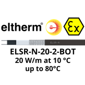
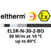
Eltherm ELSR-N self-regulating heating cables are available in three cable designs. The BOT version of the ELSR-N heating cable has a high chemical resistance and is able to withstand aggressive chemicals, oil and fuel for improved service life.
- BO: Protective braid and a thermoplastic outer jacket
- AO: Aluminium foil and a thermoplastic outer jacket
- BOT: Protective braid and a fluoropolymer outer jacket
Hazardous Area Classifications
![]() Heat Tracing Classification:
Heat Tracing Classification:

- II 2G Ex 60079-30-1 IIC Gb
- II 2D Ex 60079-30-1 IIIC Db
![]() System Classification:
System Classification:
- II 2G Ex 60079-30-1 eb IIC T6 Gb
- II 2D Ex 60079-30-1 tb IIIC T85°C Db
![]() Hazardous Area Certification:
Hazardous Area Certification:
- IECEx EPS 18.0064 U
- IECEx EPS 19.007 X
- EPS 18 ATEX 1133 U
- EPS 19 ATEX 1014 X
- CML 21 UKEX 3808 U
- CML 21 UKEX 3949 X
Temperature Class: T6
Eltherm ELSR-N Benefits
- Four nominal outputs
- UV-resistant
- Moisture proof
- Highly durable
- Efficient heat distribution
- Junction box for pipe mounting

Eltherm ELSR-N heating cables provide temperature maintenance and frost protection to pipework and mechanical services in all industries – typical applications include heating process pipework, instrument lines and storage tanks to maintain viscosity or prevent frost damage as an integral work-task of plant Winterisation.
Eltherm ELSR-N cables utilise cold-applied installation components to complete the trace heating system – no requirement for “hot-working” permit applications in potentially explosive atmospheres, including Zone 1 and Zone 2 hazardous areas.
Heat tracing Cable Selection Table – Eltherm ELSR-N
Contact T&D for technical guidance, heat loss calculations for pipework systems and optimum specification of the correct trace heating cable for your application.
| Eltherm ELSR-N Heating Cable | Nominal Output | Cable Dimensions (mm) | Cable Weight Approx (g/m) |
| ELSR-N-10-2-AO | 10 w/m at 10ºC | 13.6 x 5.5 | 91 |
| ELSR-N-10-2-BO | 10 w/m at 10ºC | 14.1 x 5.8 | 108 |
| ELSR-N-10-2-BOT | 10 w/m at 10ºC | 13.8 x 5.6 | 108 |
| ELSR-N-20-2-AO | 20 w/m at 10ºC | 13.6 x 5.5 | 91 |
| ELSR-N-20-2-BO | 20 w/m at 10ºC | 14.1 x 5.8 | 108 |
| ELSR-N-20-2-BOT | 20 w/m at 10ºC | 13.8 x 5.5 | 108 |
| ELSR-N-30-2-AO | 30 w/m at 10ºC | 13.6 x 5.5 | 91 |
| ELSR-N-30-2-BO | 30 w/m at 10ºC | 14.1 x 5.8 | 108 |
| ELSR-N-30-2-BOT | 30 w/m at 10ºC | 13.8 x 5.6 | 108 |
| ELSR-N-40-2-AO | 40 w/m at 10ºC | 13.6 x 5.5 | 91 |
| ELSR-N-40-2-BO | 40 w/m at 10ºC | 14.1 x 5.8 | 108 |
| ELSR-N-40-2-BOT | 40 w/m at 10ºC | 13.8 x 5.6 | 108 |

Eltherm ELSR-N heating cable power output on insulated metallic pipes in accordance with EN 62395-1
ELSR-N Heating circuit length
| Switch on temperature [°C] | Nominal fuse rating [A] | Heating circuit length*1 [m] | |||
| ELSR-N10-2 | ELSR-N-20-2 | ELSR-N-30-2 | ELSR-N-40-2 | ||
| 10 | 10 | 128.0 | 68.0 | 52.0 | 36.0 |
| 16 | 177.0 | 109.0 | 83.0 | 57.0 | |
| 20 | 177.0 | 129.0 | 104.0 | 71.0 | |
| 25 | 177.0 | 129.0 | 113.0 | 89.0 | |
| 32 | 177.0 | 129.0 | 113.0 | 94.0 | |
| 0 | 10 | 106.0 | 57.0 | 45.0 | 31.0 |
| 16 | 160.0 | 92.0 | 71.0 | 50.0 | |
| 20 | 160.0 | 115.0 | 89.0 | 62.0 | |
| 25 | 160.0 | 119.0 | 105.0 | 78.0 | |
| 32 | 160.0 | 119.0 | 105.0 | 88.0 | |
| -10 | 10 | 90.0 | 50.0 | 39.0 | 28.0 |
| 16 | 144.0 | 79.0 | 63.0 | 44.0 | |
| 20 | 149.0 | 99.0 | 78.0 | 55.0 | |
| 25 | 149.0 | 111.0 | 98.0 | 69.0 | |
| 32 | 149.0 | 111.0 | 98.0 | 83.0 | |
| – 20 | 10 | 78.0 | 44.0 | 35.0 | 25.0 |
| 16 | 125.0 | 70.0 | 56.0 | 40.0 | |
| 20 | 139.0 | 87.0 | 69.0 | 50.0 | |
| 25 | 139.0 | 104.0 | 87.0 | 62.0 | |
| 32 | 139.0 | 104.0 | 104.0 | 78.0 | |
| -40 | 10 | 62.0 | 35.0 | 35.0 | 21.0 |
| 16 | 99.0 | 56.0 | 56.0 | 33.0 | |
| 20 | 124.0 | 71.0 | 71.0 | 42.0 | |
| 25 | 124.0 | 88.0 | 88.0 | 52.0 | |
| 32 | 124.0 | 88.0 | 88.0 | 66.0 | |
*1 Heating circuit lengths on the following conditions:
- 230 V nominal voltage
- Delayed action circuit breakers (C-characteristic) with 80 % max. load
- Maximum 10 % line voltage drop on heating cable bus wire
- Power connection to one heater end
- In certain installation situations, the heating circuit length may vary. Please contact T&D
Eltherm video providing a step-by-step termination of ELSR-N trace heating cable using a EL-ECN termination kit.
Self-Regulating heat tracing System
A Trace Heater
B Power Connection Kit
C End Termination Kit
D Junction Box
E Pipe Mounting Bracket
F Fasteners and Self-adhesive Tapes, Foils
G Insulation Bushing
H Warning Sign
I Temperature Controller
J Temperature Sensor

Self-Regulating Heat Tracing System

Bespoke Heated Hose Designs | 40+ Years Experience from Process Heating Specialists | CONTACT US