Guidance on Fixed Gas Detection System for Use in SIS by CSA Group
Published 01 May 2020

CSA Group | Gas Detection
Guidance On Fixed Gas Detectors
EN 60079-29-3
CSA Group
Whitepaper by Hassan El-Sayed PhD, CEng, FInstMC
Business Manager Functional Safety CSA Group
- Uploaded by Chris Dodds | Sales Marketing Manager at Thorne & Derrick
Republished with kind permission of CSA Group | HazardEx 2020 Speakers Guidance On Fixed Gas Detector EN 60079-29-3 – the following Whitepaper titled Guidance of Fixed Gas Detection (FGD) Systems for use in Safety Instrumented System was presented by Hassan El-Sayed at the HazardEx 2020 Exhibition & Conference.

The original and only global information site for the hazardous area safety community | Register & Sign-up.
Below outlines all areas on the subject of gas detection in the following Whitepaper:
1. Scope of IEC 60079-29-3
2. Gas Detection System Architecture
3. Sensor Locations
4. Functional Safety Management (FSM)
5. FSM – Competency Requirements
6. General Requirements – All SILs
7. System Architecture, PFD & PFH Values
8. Factory Acceptance Testing FAT
9. Installation & Commissioning
10. Site Acceptance Testing SAT
11. Operation & Maintenance
12. System Modification, Decommissioning & Documentation
13. Typical Applications
♦ CSA Group certifies products against European and International Standards for explosion protection and functional safety, ISO 9001, ISO 14001 and ISO 45001 management systems and personnel competence certification in the fields of explosion safety, hazardous areas and environmental product installation.

Hazardous Areas & Explosive Atmospheres | Learn more about CSA

Gas Detection
THE CONFIDENCE TO GET IT RIGHT THE FIRST TIME
- Fixed gas detectors must conform to ATEX Directive 214/34/EU
- Complying with Ex protection concepts using IEC/EN 60079 series demonstrate electrical safety compliance
- What about the gas performance tests!
- What about the performance of the software systematic assessment!
- What about positioning of the gas detectors to capture the maximum area coverage
- What about the setting points configuration (LEL) to get these detectors performing satisfactory during their use when installed to perform a safety related loop
- Which standard to follow? IEC 61511 or IEC 60079-29-3 or both?
- Which one is more appropriate for fixed gas detectors when used in safety instrumented system
- Factors are likely to affect the integrity of the overall SIS than the required SIL capability
- Factors such as the number of sensing points, location, gas density, setting, redundancy, maintenance, response checking or calibration
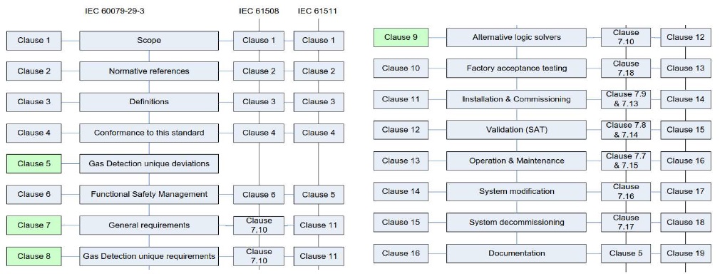
- IEC 60079-29-3 provides guidance on fixed gas detectors, it follows the safety lifecycle adopted in IEC 61508
- IEC 60079-29-2 is pertinent to gas detection coverage or transport of gas to the measuring points
- IEC 60079-29-3 specifies requirement that persons or companies who are involved in the supply chain of a fixed gas detection system should run under FSM
- It provides a framework required for gas detectors when IEC 61508 / IEC 61511 are applied
- IEC 60079-29-3 addresses the performance integrity levels of FGD where either a risk reduction target stated or used as additional safe guarding system
- IEC 60079-29-3 is not applicable to portable gas detector, if no risk reduction target sated, no need for fixed gas detection
- It covers the design and use of a complete fixed gas detection system, including associated and/or peripheral gas detection equipment which is the overall safety system
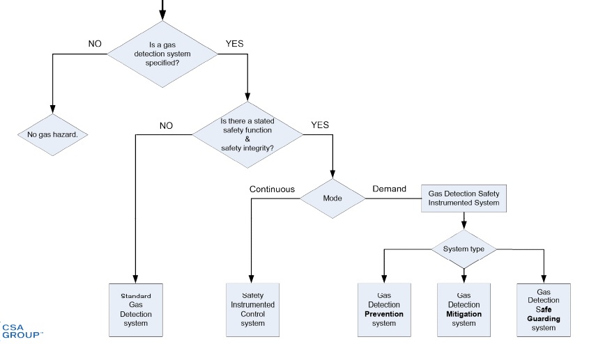
- Before applying this 60079-29-3, understanding and categorising the use of the fixed gas detection system. There are three main applications:
A) as a prevention system: the total instrumented control loop has a safety function and safety integrity level clearly defined
B) as a mitigation system : the total instrumented control loop has a safety function and safety integrity level clearly defined
C) As an additional safe guarding system – this covers those fixed gas detection control loops which operate in parallel (secondary) to SIS if primary safety system fails
The ATEX Directive | Since July 2003, manufacturers of Ex products that are placed on the European market must declare compliance with the ATEX Directive (ATEX 94/9/EC, up to 19/04/2016 and 2014/34/EU from 20/04/2016). CSA Group in the UK has been issuing ATEX certificates since 1999, 4 years before the “deadline” of July 2003. In that time CSA have supported thousands of organisations to meet their hazardous area certification goals. With one of the largest teams of qualified Certification Engineers anywhere in the world, and the leading issuer of ATEX approvals, CSA Group can offer an end-to-end certification service to meet your needs.
Gas Detection ‘Safety Instrumented’ System Standards
IEC 61508 – Gas Detection Device Manufacturers
IEC 61511-1, IEC 61511-2, IEC 61511-3 – System Integrators & Gas Detection System Integrators
IEC 60079-29-3 System Integrators & Gas Detection System Manufacturers & Integrators
| Clauses Note: *** Most appropriate ** Advisable * Useful |
Definitions | Conformance | GD Unique Features | Functional Safety Management | General Requirement | FGD Unique Requirements | Alternative Control Units (LS) | FAT | Installation & Commissioning | SAT | IOM | System Modification | System Decommissioning | Documentation |
| Consultant, Vendor, SI, Manufacturer |
*** | *** | ||||||||||||
| General management | * | * | * | * | * | * | * | * | ** | ** | ** | * | * | |
| Design engineering management | *** | * | *** | *** | *** | *** | * | * | * | *** | *** | ** | ** | |
| System engineer | *** | * | *** | *** | *** | *** | *** | ** | ** | * | *** | ** | ** | |
| Commissioning /installation engineer | ** | * | ** | ** | * | * | *** | ** | * | *** | ** | ** | ** | |
| Service / quality / operation engineer | ** | * | *** | *** | *** | * | *** | ** | *** | *** | *** | *** | *** | |
| Training officers | *** | * | *** | *** | *** | ** | * | * | * | *** | * | * | ** |
Gas Detection System
Gas Sensor Location
- Gas sensors do not have direct contact with source of gases, hence Fixed Gas Detection must be positioned where maximum gas leak / vapour can reach the sensing element as per IEC 60079-29-2
- Gas sensors (passive) fitted with a passive filter element to protect the sensor membrane from airborne dust, dirt or moisture, require scheduled inspection and proof testing
- Gas sensors (active) fitted with catalyst filter, do not have a defined life time, behaves like passive filters, require scheduled inspection and proof testing
- Measuring performance of all sensors should be tested against the suitability of the application. Sensors may become poisoned, inhibited, saturated, less sensitive, hydrated, sleep effect, optical interference, optical blockage, etc
- Sensors failures can be detected by diagnostics (DD) and others cannot be (DU), therefore, proof testing and calibration is required
- Some sensors (catalytic) suffer from CCF, such as adverse chemical reactions
- Gas sensors must be inspected for negative reading (caused by drift)
- Hazard and risk analysis should consider all hazards associated with other gases and vapours, which include short term and long term effects
- Most gas detection sensors suffer from cross sensitivities which may increase or decrease the response to gas detection
- Conformance with metrological performance standards is required for all SIL levels
- Handling of fault signals shall be clearly defined in the safety function. It is not desirable of a fixed gas detection system to generate a false (spurious trip), shutdown / evacuation process
- Sensors shall be capable to generate an over-range measurement
- Calibration shall be advised by the manufacturer and clearly described in the IOM
- Maximum and minimum alarm set points shall be recommended to guard against spurious trips
Functional Safety Management (FSM)
- A functional safety management system shall be in place during each phase of the fixed gas detection system life cycle, details of all the SIFs shall be provided, SIL target, organisation management activities, responsibility identified, competency records, knowledge and experience of applicable standards, protections systems, safety planning, H&RA associated with any fixed gas detection system.
- Independent review for all SIL target and it shall be as defined in accordance with IEC 61508, part 1 clause 8
| No SIL (0) | SIL 1 | SIL 2 | SIL 3 | |
| Gas Detector | A | A | HR | M |
| Sub-system Supplier | A | HR | M | M |
| Gas Detection System Supplier | A | M | M | M |
| System Integrator or Equivalent | A | M | M | M |
A = Advisory HR = Highly Recommend M = Mandatory
FSM – Competency Requirements
Competence is the ability to undertake responsibilities to perform activities to a recognised standard on a regular basis. Evidence must be provided.
Understanding the potential consequences of a failure.
Training or competency in FS/SIL assessment for control systems. All qualifications shall be documented.
General Requirement…
Designing of Fixed Gas Detection (FGD) system shall be in accordance with safety requirement specification.
All elements shall conform to IEC 61508, and IEC 61511 may be used.
A FGD system shall be designed to ensure easy operation, maintainability and testability.
The action of a FGD system under special state or gas alarm condition should not automatically switch to a safe state.
The SRS shall clearly define which functions of the fixed gas detection system have an allocated safety integrity level, define safety and non-safety functions.
General Requirements – All SILs
Behaviour of FGD under dangerous failures by diagnostics or proof tests shall be referenced to SRS, and results in initiation of a specified action to achieve a safe state or brought to operator to initiate a safe state, or repair action to keep safety function available within the MTTR. If SF cant be repaired within MTTR, the end user is responsible for initiating additional risk reduction actions.
Behaviour of FGD under safe failure conditions, same actions as above.
Power supply is not part of the safety function when the entire FGD system is designed to operate in a fail-safe mode. If fail safe is not included, then reliability of the PWR Supply should be included.
System with 1 single PWR supply, a fault signal shall be initiated when power supply fails.
System with redundant PWR SPLY, no loss of safety function shall occur during switching.
System supported with UPS, no loss of safety function shall occur during transition.
A gas detector (including sensor) shall conform to IEC 61508-1,2 and 3, metrological performance to (IEC 60079-29-1 or 4).
A gas detector control unit (Logic Solver) including SW shall conform to IEC 61508-1/2/3 and shall conform to pertinent metrological performance standards, such as (IEC 60079-29-1, / 4) . • Final element shall conform to IEC 61508-1/2/3.
Visual indication shall be provided to display status under normal, abnormal, alarm state, special state, maintenance, and shall be unambiguous and may include, units measured, range, over range, special state, diagnostics data, peripheral equipment.
Switching outputs provide alarms, and special state signal, or may initiate safe actions, fault outputs shall be fail safe.
All switching output configuration shall be specified in the SRS.
System architecture, PFD and PFH values.
All alarms shall remain tripped until a manual reset is initiated.
All switching outputs shall be capable of operating under full load conditions.
The architectural constraints as defined by IEC 61508 apply to a fixed gas detection system. Each gas detector, sub-system and complete system shall conform.
For process industries, IEC 61511 may be used, the Probability of Failure on Demand (PFD) values as defined by IEC 61508 apply to a fixed gas detection system.
The total sum of all sub-system PFD values used in a single gas detection safety loop shall conform to the safety integrity target as stated in the safety specification.
Proof of systematic capability shall be part of the conformity assessment.
Factory Acceptance Testing FAT
FAT should be specified during the validation plan, it may include the following tests:
a) pass/fail criteria, procedures for test records data/results,
b) HW/SW versions of the EUT, corrective actions, system modifications,
c) configuration management, external suppliers, testing equipment,
d) types of gases, persons competencies, and description of black box test.
FAT should be executed as per the FAT test plan, verification shall :
a) be performed to all supporting document for completeness,
b) correct revision approval, impact analyses showing root cause of any failure
c) justification of changes if required
Installation and Commissioning
Installation methods and commissioning procedures should be specified during the design phase of the FGD system and should include as a minimum:
The installation activities;
- the person, department or organisation responsible for the installation activities;
- precautions to take when the installation is within an hazardous area;
- electrical tests required to satisfy the electrical installation is correct (before the system is energised);
- the types of tests to be performed on system start-up;
- the PASS/FAIL criteria, including when to abort the tests subject to a single or multiple test failures;
- procedures for the recording of test data/results and the HW/SW versions of the EUT
- procedures for corrective actions; for system modifications or changes; for conflict management;
- test equipment to be used, supported by valid equipment calibration certificates;
- test gases to be used, supported by valid gas composition certificates;
- test persons’ competencies and persons in attendance;
Execution of Fixed Gas Detection Systems
The installation should be conducted in accordance with the installation plan.
The commissioning should be conducted in accordance with the commissioning plan.
Before installation and commissioning, all documentation shall be checked as above.
Site Acceptance Testing SAT.
System Validation
System Validation Test should be specified during the design development phase of the fixed gas detection system and should include as a minimum:
- validation methods to ensure that the installed FGD system performs the safety function as stated in the SRS
- validation methods to show the FGD operates correctly under, normal, abnormal, special state condition and fault condition
- procedures to manage system modification as shown in FAT
- competencies records for the persons conducting the work
- procedures for recording test data/results and HW/SW versions of the EUT
Execution of Fixed Gas Detection Systems
The System Val. test should be conducted in accordance with the System V. Test plan.
Before the System Val. Test, all documentation shall be checked for completeness, rev etc.
Operation and Maintenance
Outline the minimum routine service requirements, including proof testing which should be executed during the phase of operation and maintenance.
Planning Phase
Should be specified during the design phase of the FGD system and should include as a minimum:
- detailed records of the system’s performance during normal and abnormal operation,
- the number of demands placed on the system;
- the frequency of scheduled system maintenance activities;
- the maximum number of safety loops which are in override during any maintenance
- detailed maintenance records including faults found, corrective or repair actions taken, spare parts used,
consumables used and any changes of system performance which may, in the future, affect the safety function; - detailed proof test results; and
- detailed corrective actions taken if a proof test fails
Execution
The FGD system shall be operated as detailed in the overall system safety manual.
The proof test will be dependent upon how close to the “as new” condition the system is restored.
For effective proof test, it is necessary to detect 100 % of all dangerous failures. In practice 100 % is not easily achieved for other than low-complexity E/E/PE safety-related systems, this should be the target.
Cross referencing between IEC 61508 & IEC 61511.
System Modification, Decommissioning & Documentation
Modifications to any fixed gas detection system shall be planned, reviewed and authorised prior to any modification being perform. It shall include:
- Impact analysis, ensuring alternative measures available for maintaining SIL, any associated Ex documentation, validation methods for the implemented change, verify any associated functions (not modified) not been affected, competency, documentation control process, etc.
- A modification / decommission activities shall not commence without proper authorisation.
Documentation: all single documents, including individual instrument operating manuals, safety manuals, electrical schematics, parts lists, data sheets etc., should be:
- fit for purpose and applicable to the application;
- accurate and easy to understand; revision controlled, structured, clearly defined information for each part of the life cycle;
- contain all results from FAT, Commissioning and Site Validation (SAT)
Include recommended maintenance activities, complete with a supporting test program and record sheets;
Include recommended proof test activities, complete with a supporting test program and record sheets; and list recommended operational spare parts.
A total Safety Manual should be compiled which includes as a minimum the following: safety function and integrity per safety loop, restrictions of use (including consumable parts e.g. filters), operational procedures, maintenance procedures, a fault finding guide and override procedures.
All product certificates should be supplied with the associated test report where available.
Revision control of all documents should clearly state the product or system to which it applies, including the hardware revision and software version of the product or system.
Typical Applications
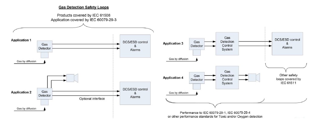
Typical Applications
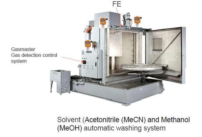
Typical Application (Automated Washing System for Pharmaceutical use)
Glossary of Gas Detection Standards
- IEC 60079-29-3: Explosive Atmospheres – Part 29-3: Gas Detectors – Guidance on Functional Safety of Fixed Gas Detection Systems
- IEC 60079-29-2: Explosive Atmospheres – Part 29-2: Gas Detectors – Selection, Installation, Use & Maintenance of Detectors for Flammable Gases & Oxygen
- IEC 61511-1:2016 Functional Safety – Safety Instrumented Systems for the Process Industry Sector – Part 1: Framework, Definitions, System, Hardware & Application Programming Requirements

Thorne & Derrick are Crowcon Distributors – manufacturers of high-quality portables and fixed gas detection product with a reputation for reliability and technical innovation in hazardous areas and explosive atmospheres.


Thorne & Derrick | Detecting Flame | Heat | Gas
Experts in Equipment
for Explosive Atmospheres
FOLLOW US
Follow our Showcase Page on LinkedIn to receive hazardous area product innovations, industry news, whitepapers, videos, technical tips and training webinars for professionals involved in the explosive atmosphere industries.

