Use Of Light Source Encapsulation In IECEx/ATEX Zone 1 Hazardous Areas
Published 16 Mar 2022

-
Whitepaper By Appleton August 2018
ATEX LED LIGHT FITTINGS
Light Source Encapsulation
Explosive gas atmospheres present specific risks from ignition caused by electrical component operation and failure. Products used in these applications must offer protective features to insure isolation of potential ignition sources from unstable environmental materials.
For hazardous area lighting applications within zones that experience intermittent exposure to explosive gas atmospheres, prescriptive codes and standards have been established to insure these systems operate in a safe manner.

Appleton ATX FELED | LED Light Fittings for Hazardous Areas
Introduction
This paper explores the differences in hazardous exposure protection methods between conventional light sources and solid-state technology, with a review of code requirements and Zone 1 equivalencies that are applicable. Aspects of damage resulting from interaction of light source ignition sources and flammable gaseous materials, and the maintenance,
reliability implications of the protection concepts employed are presented, as they apply to the design, application and continuous service.
This paper also compares the optical and energy utilisation of light sources, and the effects of protection concepts, including flameproof and encapsulated product approaches on product performance initially and over the service life of products.
Background
Hazardous location electrical codes and standards throughout the world are defined by two distinct paths. In North America, a “Class, Division” system is used as the basis for area classification of hazardous (classified) locations. In other parts of the world, explosive atmospheres are addressed through a “Zone” system based on the International Electrotechnical
Commission (IEC) and European Committee for Electrotechnical Standardization (CENELEC) standards.
IECEx/ATEX(1) (ATEX is derived from the French title of the 94/9/EC directive ‘Appareils destinés à être utilisés en ATmosphères EXplosibles’) requirements are defined by two directives. For equipment, ATEX 95, directive 94/9/EC (manufactured prior to April 2016) and 2014/34/EU Article 44 (manufactured after April 2016) defines product requirements, while ATEX 137, directive 99/92EC addresses minimum requirements for workplace safety. The most significant component of IECEx/ATEX directives is that the level of hazard probability is divided into three Zones (See Table 1.0).
In the United States and Canada, methods of protecting hazardous area electrical equipment for different material exposures and hazardous locations are divided into three Classes, and two Divisions. The Classes reflect the type of hazard and the explosive characteristics of the material, while the Divisions reflect the risk of fire or explosion. With a few small differences, these two countries employ similar protection methods and product standards.
While specific requirements differ, the Unites States and Canada have incorporated a similar Zone System for Class I hazardous locations in recent electrical code updates (see Table 2.0 and 4.0). Both systems provide effective solutions for protection used in hazardous locations.
For the purposes of this paper, the focus is on IECEx/ ATEX Zone 1 (which generally includes subsequent coverage of North American Class I, Division 1, and Class I, Zone 1) in defining approaches to equipment protection methodology for hazardous locations in which flammable or explosive gases are likely to be present, either continuously, or intermittently (Table 1.0).
Standards within IECEx/ATEX Zone 1 include specifications for equipment protection concepts within three divisions related to Equipment Protection Level (EPL), (ATEX 1G, 2G, and 3G, corresponding to IECEx EPL Ga, Gb and Gc), which are then included in defining the protection concept utilized (see Table 3.0).
Table 1.0 – Classification Systems by Frequency of Exposure Occurrence
| Frequency of Occurrence | North American Class I Division System | IECEx/ATEX Zone System |
| Hazardous gas, vapor or mist | ||
| Continuous – Where an explosive atmosphere consisting of air and dangerous substances in the form of gas, vapor or mist is present continuously or for long periods. |
Class I, Division 1 | Zone 0 |
| Intermittent – Where an explosive atmosphere consisting of air and dangerous substances in the form of gas, vapor or mist is likely to occur in normal operation occasionally. |
Zone 1 | |
| Abnormal Condition – Where an explosive atmosphere consisting of air and dangerous substances in the form of gas, vapor or mist is not likely to occur in normal operation or for a short period only |
Class I, Division 2 | Zone 2 |
Table 2.0 Hazardous Area Definition (2)
| ATEX equipment group | ATEX equipment category and environment type | Zone classification ATEX/IECEx | Required equipment protection level (EPL) | Class/Zone classification (North America) | Class/Division classification (North America) |
| II | 1G (Very High) | Zone 0 | Ga | Class I, Zone 0 | Class I, Division 1 |
| 2G (High) | Zone 1 | Gb | Class I, Zone 1 | ||
| 3G (Normal) | Zone 2 | Gc | Class I, Zone 2 | Class I, Division 2 |
Table 3.0 ATEX/IECEx Protection Concepts
Typical Electrical Equipment Exposed to Flammable Gases, Vapors and Mist
| Symbol | Type of protection | Basic concept of protection | Suitable for Zones | Typical EPL | EN/IEC Standard | ||||
| 0 | 1 | 2 | Ga | Gb | Gc | ||||
| eb | Increased safety | No arcs, sparks or hot surfaces, enclosure IP54 or better | • | • | • | 60079-7 | |||
| d | Flameproof | Containment of the explosion | • | • | • | 60079-1 | |||
| ia | Intrinsic safety | Limitation of spark energy and surface temperatures | • | • | • | • | 60079-11 | ||
| ib | • | • | • | ||||||
| ic | • | • | |||||||
| ma | Encapsulation | Keep the flammable substances out | • | • | • | 60079-2 | |||
| mb | • | • | • | ||||||
| mc | • | • | |||||||
Table 4.0 Protection Concepts for North America and Canada
Typical Lighting and Electrical Equipment Exposed to Flammable Gases, Vapors and Mist
| U.S.Code | Canadian Code | Type of protection | Basic concept of protection | Class I, Division | Class I, Zone | U.S.Standard | Canadian Standard | |||
| 1 | 2 | 0 | 1 | 2 | ||||||
| AEx e | Ex e | Increased safety | No arcs, sparks or hot surfaces | • | • | • | ISA 60079-7 | CSA E60079-7 | ||
| AEx d | Ex d | Flameproof | Contain the explosion and extinguish the flame | • | • | • | ISA 60079-1/ UL 1203/FM 3615 | CSA 60079-1 | ||
| AEx ia | EX ia | Intrinsic safety | Limit energy of sparks and surface temperature | • | • | • | • | ISA 60079-11/ FM 3616 | CSA E60079-11 | |
| AEx ib | EX ib | • | • | • | ISA 60079-15 | CSA E60079-15 | ||||
| AEx nL | EX nL | Limited energy | — | • | ISA 60079-15 | CSA E60079-11 | ||||
| AEx m | Ex m | Encapsulated | Keep flammable gas out | • | • | • | ISA 60079-18 | CSA E60079-18 | ||
| AEx ma | N/A | • | • | • | • | Not Applicable | ||||
| AEx mb | • | • | • | |||||||
Light Source Technology Factors
Light source technology has a profound effect on protection concepts. Light sources, such as HID, halogen and fluorescent present several challenges to protection from exposure to hazardous gases.
Due to short service life, glass lamp technologies require frequent service of spent lamps over the life of a product. Further, internal arc sources and high temperature filaments that exceed the flash point temperatures of all gases within Zone 1 applications, demand complete isolation of the lamp and its surrounding compartment from atmospheric gases present. HID and halogen technologies also produce high temperatures that demand increases in luminaire cavities to reduce surface temperatures.
Due to the frequency of access for regular lamp replacement, risks of failure of compartment seals is increased as the product is serviced over its lifetime.
LED technology, due to relatively low surface temperature, and extremely long service life, provides opportunities to incorporate protection methods, such as encapsulation, to reduce exposure risks while significantly reducing the cavities of luminaires themselves. Further, due to the high efficacy of LED sources, the total energy and subsequent related heat, is reduced, presenting lower external luminaire surface temperatures, with significantly smaller luminaire cavities (and subsequent external dimensions).
Table 5.0 illustrates the characteristics of the light source, and how these impact protection approaches.
Table 5.0 Light Source Comparison
| Source | Arc hazard | Surface temperature hazard | Luminaire cavity requirement (surface temperature reduction) | Maintenance interval * (hours) | Maintenance access/ failure risk | Potential for encapsulation |
| Halogen/Incandescent | Moderate | High | Large | 500 – 3,000 | High | n/a |
| Metal Halide | High | Very High | Large | 5,000 – 20,000 | High | n/a |
| HPS | High | Very High | Large | 5,000 – 30,000 | High | n/a |
| Fluorescent | Moderate | Moderate | Moderate | 5,000 – 30,000 | High | n/a |
| LED | None | Low | Small | 70,000-100,000 | Minimal | Light source and electronics |
* Light source maintenance interval based on range of hours to first failure (infant mortality) of source to longest expected full service life expected before maintenance is required to restore product to functional service.
Solid State Technologies (LED) Impact On
Protection Approach
LED light sources present several opportunities to reduce luminaire size and weight. The characteristics of LED light sources and supporting electronic components are particularly well suited to the application of encapsulation to isolate both electrical connections and heat sources from intrusion of gases.
Optical encapsulants can also include features that eliminate, or enhance optical performance, reducing product mass and scale, resulting in lower profile designs in compact enclosures. Further, the lower operating temperatures of LED sources allow the use of polymer materials for lenses and optical enclosures.
Encapsulation provides additional advantages in prevention of explosion or damage, application in >55°C (131°F) ambient environments, and provides for common construction beyond Zone 1, including Zone 2 as well as dust exposure Zones 21 and 22.
Encapsulation Approach, Materials, and Design Considerations
Typically, encapsulation of electronic components for LED products is identical to other encapsulated electrical and electronic components, using common potting polymer systems, such as epoxies, silicones, and polyurethanes, which can serve a dual purpose of providing thermal conductivity, or isolation depending on product design requirements.
For optical encapsulation, the use of silicone and siloxane hybrid materials is most common. High quality optically clear encapsulants suited to Zone 1 encapsulation, typically deliver 90% to 95% transmission, with long service life at temperatures up to 200°C (392°F) without yellowing for the service life of the LEDs encapsulated(2). These encapsulants may be used over LED arrays with no other optical components, molded into optical forms to act as lenses and/or diffusers, or around and under discrete silicone, polycarbonate, or Poly(methyl methacrylate) (PMMA) optical components.
Approaches to encapsulation vary between product designs. The most economical approach is to encapsulate electronics and LEDs into luminaire bodies, essentially sealing the interior into a non- serviceable assembly that is permanently sealed. This approach requires the entire luminaire to be replaced at the end of service life. Modular designs utilize individually encapsulated components attached within the housing, that are able to be replaced at the end of service life without necessitating complete luminaire replacement.
In either construction, there remains space within the luminaire that remains un-encapsulated. For this reason, while encapsulation provides additional protection in Zone 1 applications, luminaires utilizing encapsulation or encapsulated modules will also include additional areas within the product covered under other equipment protection levels (EPLs).
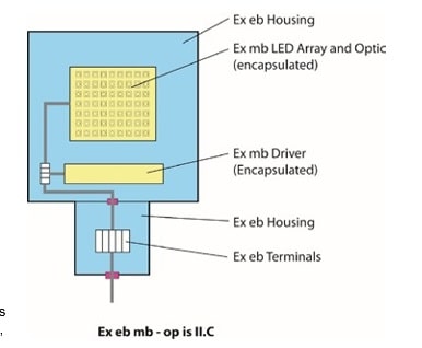
This includes the cavity not filled with encapsulants, wire connection compartments, and wireways between components that are not otherwise covered. However, the utilization of Ex mb (encapsulation) reduces the requirement of protection of these uncovered cavities from Ex d (Flameproof) to Ex eb (Increased Safety) to fully satisfy the requirements of Zone 1 application.
Figure 1.0 below illustrates the combination of EPLs applied to a luminaire that employs encapsulated modules within a Zone 1 design.

Figure 1.0 – Example Composite Protection Method Diagram
While encapsulation provides additional protection within luminaire construction, which can be used to reduce product size and weight, the connection of the luminaire, and the housing surrounding the encapsulated modules must be considered and designed under eb, or “Increased Safety” protection methods. Encapsulation of components or modules does not replace this requirement.
Luminance Effects and Efficiency
The comparison of total luminaire efficiency between conventional flameproof (Ex d protection method) products (HID, fluorescent and LED) and LED products that utilize encapsulation for additional protection requires consideration of several variables. While large reflectors and high efficiency optics may produce a theoretical advantage over encapsulated products, the advantage is very small, considering that modern encapsulants deliver transmission of >90%.
Additionally, integration of optical features into the encapsulant itself, over sealing a molded separate optic onto the LED array with silicone, reduces light loss.
This integrated approach produces optical performance that is equivalent to non-encapsulated luminaire designs.
Optical systems for HID sources generally account for greater losses in efficacy than encapsulant materials impart on LED sources, while LED optics (both encapsulated and bonded) tend to be more efficient and suffer less degradation over time due to dirt accumulation, surface degradation due to aging and maintenance contact, and surface area accumulation of debris, scratches, and material degradation.
Additionally, LEDs produce significantly higher efficacy than any other light source. This produces a margin of tolerable loss for application of protection methods, such as encapsulation, to realize gains in luminaire design, reduced scale, streamlining appearance, thermal management, and reducing weight.
Testing Requirements
Testing of encapsulated components within luminaires is no different than any other protection method. All materials utilized in products intended for Zone 1 applications must be fully tested, including employment of HALT (Highly Accelerated Life Test) methods, salt spray testing, as well as quality controls to insure product integrity remains over the intended service life.
While there are no universal or established HALT parameters for testing encapsulated luminaires, the following test parameters could be considered a baseline for establishing product performance under conditional extremes:
- Strife test: increase ambient until failure (105°C (221°F) or more) (4 hours at each level)
- Thermal Shock Test: -40°C to 125°C (-40°F to 257°F), 30 minutes each, 250 cycles
- High Temperature Steady State Test: LED T-case 105C, 1000 hours
- Low Temperature Steady State Test: -55°C (-67°F), turn on, 500 hours
- Temperature and Humidity Stress Test: 85°C (185°F), RH: 85%
For products utilizing encapsulation of LED sources within optical systems, additional consideration of adhesion of encapsulants to LED arrays, optical components (where employed), and degradation of optical performance over the service life of the sources utilized, is required. The unique interface of light source components, optics and encapsulant materials, present differences in coefficient of expansion conditions that must be tested over the entire operating temperature and humidity range anticipated for the intended application.
Conclusion
The opportunity to employ the protection concept of encapsulation presented by solid-state technology is a significant improvement over conventional flameproofing, in all areas of product design including physical construction, optical design and energy efficiency, through use of efficient LED light sources over conventional lamps (which cannot be encapsulated), and protection from damage caused by interaction of light sources with flammable materials
in Zone 1 applications. Encapsulation delivers Ex mb protection, eliminating the need for flameproof construction, while also providing specific light beam pattern generation, with a resulting increase in total system performance (efficacy and precision of illumination delivery) over a reflector/lamp flameproof fixture.
The Appleton Lighting Retrofit Calculator helps users visualise savings accomplished by retrofitting their current lighting system to an Appleton LED solution. Calculate maintenance, energy and environmental savings achieved by upgrading to Emerson’s Appleton LED luminaires with this interactive tool.
APPLETON ATX HAZARDOUS AREA ELECTRICAL EQUIPMENT
Full range of Appleton ATX Hazardous Area Products available from Thorne & Derrick stock.
- Plugs & Sockets | Zone 1 & Zone 2 Hazardous Area Plug & Sockets EX ATEX Certified
- Isolators & Safety Switches | Zone 2 Isolators & Safety Switches EX ATEX Certified
- Lighting | Zone 1 & Zone 2 Hazardous Area Lighting EX ATEX Certified
- Junction Boxes | Zone 1 & Zone 2 Hazardous Area Junction Boxes EX ATEX Certified
- Control Stations | Zone 1 & Zone 2 Hazardous Area Control Stations EX ATEX Certified

EXPERTS IN EQUIPMENT FOR EXPLOSIVE ATMOSPHERES
leaders in ATEX Innovation To The Hazardous Area Industries
Thorne & Derrick are leaders in the development and distribution of Product Innovations that deliver significant improvements to clients plant, people and operational safety in the explosive atmosphere industries.
Your proactive problem solvers experienced in succession planning for the replacement of obsolete, non-conformant and legacy equipment in hazardous areas.
Your first-choice provider of innovative and competitive solutions to ensure ATEX & IECEx Compliance for Hazardous Area Electrical, HVAC & Process Instrumentation Equipment to UK and international projects.
Control Panels | Plugs | Isolators | Enclosures & Junction Boxes | Lighting | Control Stations | Motor Starters | Heat Trace | Gas Detection | Flame Detection | Process Instrumentation | Process Heating | Ventilation Fans | Security Access Control


