Level Sensing Techniques & Solutions To Level Sensing Problems By Deeter Group
Published 29 Sep 2016

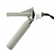
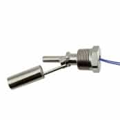
Level Sensors & Float Switches
- By Chris Dodds : estimated reading time 12 minutes
Liquid Level Sensors – Introduction
Over the years many techniques have been developed to provide information about the level of liquids or granular solids.
Many processes involving the storage, movement or processing of liquids require careful control of liquid level to ensure correct operation of the plant or equipment involved.
This application note reviews some of the more popular techniques used for liquid level sensing and describes the application challenges that need to be considered for satisfactory long term operation.
Basic Techniques
Direct Level Measurement
Most measurement methods can be categorised into one of two groups – direct and indirect (or inferred) methods.
As the term implies direct methods involve measuring the variable of interest (in this case the height of the surface level of a liquid) directly.
Common examples of direct measurement techniques that most people will have encountered are a dipstick to indicate the level of oil in an internal combustion engine sump.
Other examples are a ruler on the bank of a river to show the depth of water or a sight glass on a fuel tank to show the level of fuel within the tank.
These methods are simple and inexpensive but prone to errors and can only be used where an operator has access to the indicator or a CCTV system can be justified.
Where an indication of level is required remotely and greater precision or reliability are necessary then electronic / electro-magnetic / electro-mechanical direct measurement systems are often employed.
Indirect Level Measurement
In some circumstances an indirect method of measuring the level of a liquid may be preferable if not the only, viable, method.
For example, the liquid may be highly viscous (hot toffee) not allowing the free movement of a conventional float. In these circumstances other variables can be measured that correlate to liquid level.
For a liquid of constant density and temperature its mass is related to liquid level in a container of constant cross section.
So the weight of the contents is an indirect measurement of the height of the surface level.
Firing a beam of energy (ultrasonic, microwave or light) and measuring the time of flight for the reflected beam to be received also is indirectly related to the level liquid.
Indirect methods tend to be more costly and often are subject to more errors than direct methods.
Electrical Output
In terms of the electrical output(s) provided by liquid level sensors these can be grouped as binary on/off or semi-continuous and continuous analogue output.
Binary on/off sensors provide a switch contact change at each level of interest, usually 4 levels are of interest – AlarmHi, Hi, Lo and AlarmLo., but other configurations are possible. Semi-continuous sensors offer multiple values of analogue voltage, current or resistance to represent multiple liquid levels.
Depending on the physical size of the components used it is possible to resolve differences in liquid level as small as 1-2mm.
True continuous level indicators provide 0 to 10v or 4 to 20mA outputs representing every possible liquid level from zero to full scale.
These sensors measure the conductivity of the rising or falling liquid; this indicates a changing resistance related to liquid level.
Recent developments in this field include a resistive tape that is attached to the side of the liquid container.
Hydrostatic pressure causes the tape to change resistance this change can then be processed to provide a continuously varying current or voltage as an analogue of the liquid level.
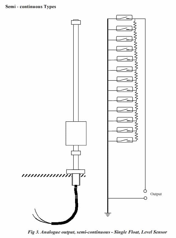
Deeter Electronics specialises in direct methods of sensing liquid level using magnetic float chambers and reed switches to indicate liquid level in a discrete level binary (on/off) or semi continuous (stepped analogue output) arrangement as shown in figures 1. to 3. below.
This technology is scaleable, affordable, relatively simple and highly reliable. By careful selection of the wetted materials, number and type of reed switch and magnetic floats, a broad range of applications can be addressed.
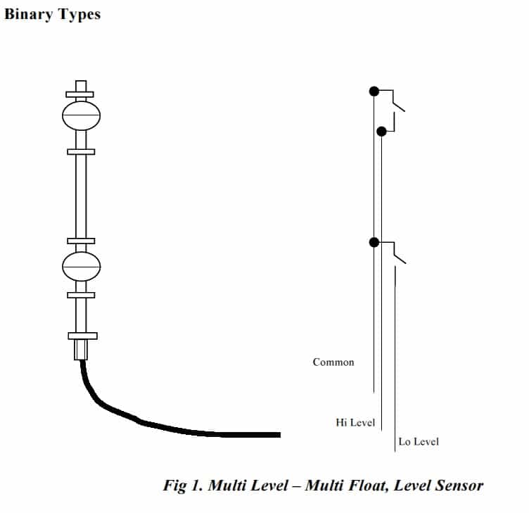
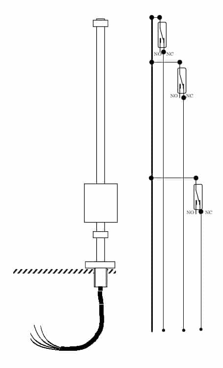
Fig 2. Multi Level – Single Float, Level Sensor
Reed Switches and Load Switching
As mentioned before Deeter Electronics specialises in liquid level sensors employing electromagnetic technologies.
This technique uses a buoyant chamber (float) with an annular magnet (doughnut shaped) sealed inside.
The magnetic field is concentrated in the hole in annulus. The float passes up and down a stainless steel or plastic float stem within which is contained a number of reed switches mounted at carefully chosen positions along the length of the stem.
As the float passes by each reed switch it operates indicating the presence of the float and thus surface level of the liquid.
There is a small difference between the surface level of the liquid and the actual position of the reed switch caused by the buoyancy of the float, the specific gravity of the liquid being measured the strength of the magnetic field and the sensitivity of the reed switch.
All of these factors are taken into account when the float is designed. Typically the stem of the float has an outside diameter less than 10mm.
Allowing for the wall thickness of the stem leaves less than 8mm depending on stem stiffness in which to mount the reed switches and electrical wiring or printed circuit board. Clearly the reed switches are quite small.
This small size limits the electrical switching capabilities of the reed switch contacts. Despite this limitation currents in the ampere range and voltages up to 500v can be safely and reliably switched.
However, once subjected to an overload, reed switches become erratic and unreliable in their operation; sometimes refusing to open circuit or make a good low resistance connection.
The electrical ratings for reed switches are always stated for purely resistive loads.
Rarely are loads purely resistive, this can lead the unwary user into difficulties. Even in low voltage systems high transient voltages and currents can occur which if switched by the reed switch, without adequate protection circuitry, will damage the contacts and cause unreliable operation thereafter.
Capacitive Loads
Capacitive loads are characterised by high initial charging currents and if the load is then shorted, a high discharge current.
Unless protection circuitry is applied the switch will be damaged by these currents and become unreliable. Examples of capacitive loads are shown in the diagrams below.
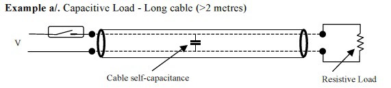
When the reed switch contacts close the self-capacitance of the cable is charged to voltage V. Because there is very little resistance in the charging circuit the instantaneous current that flows can be very large.
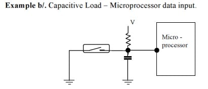
When the reed switch closes the capacitor is discharged. Because the resistance in the circuit is very low the instantaneous discharge current is very high and damage is caused to the reed switch contacts.
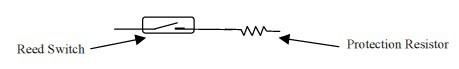
Protection Circuitry for Capacitive Loads
Limiting the large current in the charging and/or discharging mode provides protection. Typically inserting a 27-ohm resistor in series with the reed switch contacts is sufficient to limit the charging/discharging current to safe levels.
To calculate the resistor value for your specific application divide the charging voltage in volts by the safe maximum reed switch switching current in amps.
This gives the reed switch series protection resistance value in ohms. Choose the nearest higher standard value resistor.
Inductive Loads
Inductive loads are characterised by current flow lagging the applied voltage and large reverse emf’s being generated when the load is de-energised.
Unless protection circuitry is applied the reed switch contacts will be damaged by the reverse emf’s generated when the load is de-energised. Examples of inductive loads are shown in the diagrams below.
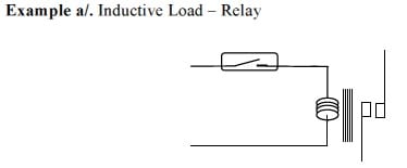
Because relays typically have higher current and voltage switching capabilities they are often used to buffer the reed switch from switching the load directly.
However, relays are inductive and this can cause damage to the reed switch contacts.
Relay coils can have sufficiently high inductance that switching the coil current with a reed switch causes damage to the reed switch contacts caused by arcing due to the high reverse emf that is induced in the coil as it is de-energised.
Depending on whether the coil is AC or DC energised the protection circuitry varies as shown below.
Protection Circuitry for Inductive Loads AC Circuits
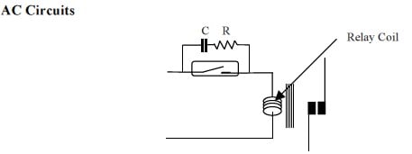
The capacitor and resistor in parallel with the reed switch absorb the energy stored in the relay coil magnetic field when it is de-energised.
This protects the reed switch contacts from damage due to electrical arcing.
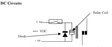
When the relay coil is de-energised the collapsing magnet field induces a voltage in the coil which is in reverse polarity to the supply voltage.
The diode forms a short circuit across the relay coil and safely absorbs the stored energy.
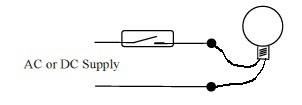
Incandescent Lamp Loads
Incandescent lamps, also called filament lamps, are sometimes used in liquid level measurement systems to provide an easily visible indication of the current liquid level. They are inexpensive and if used properly have a long and reliable life.
Whilst, as an electrical load, they are mostly resistive, having low capacitance and inductance, their resistance is extremely low when cold.
At switch on therefore, a significant current flows before the filament warms up to its normal operating temperature. This transient current can be sufficient to damage the reed switch contacts.
Protection Circuitry for Lamp Loads
Whether the supply is AC or DC, protecting the reed switch contacts can be achieved by limiting the transient current until the lamp filament reaches operating temperature.
Thus a series resistor R1 equal to the supply voltage divided by the maximum reed switch switching current in amps can be used or alternatively a parallel resistor R2 selected to maintain the temperature of the filament sufficiently high that the switch on current does not exceed the capability of the reed switch contacts. Both these protection circuits are shown below.
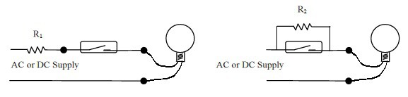
When selecting resistor R1 or R2 remember to take into account the power rating required to dissipate any heat generated.
Environmental Considerations Chemical Compatibility
Temperature
Knowledge of the expected range of temperature of the liquid and the immediate environment surrounding the liquid level sensor is critical to ensure that the sensor operates reliably.
By careful selection of the materials used in the construction of the sensor it is possible to operate in liquids at up to 300ºC.
When operating at high temperatures, selection of the magnetic materials used is important because there is a tendency to de-magnetise at high temperatures.
Similarly, the reed switches and any electrical conductors, insulation and solder connections must be specified for operation at elevated temperatures also.
Pressure
Some applications require level measurement in a pressurised vessel. In these instances the pressure tends to crush the float and stem of the sensor.
Floats and stems are avail able in a variety of materials which can withstand very high pressures without deforming.
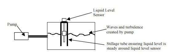
Turbulent Liquid
In applications where a pump may be used to maintain liquid level in a tank the liquid surface can exhibit waves.
Obviously the liquid level sensor float will follow these waves and this can lead to erratic and unnecessary switching. To avoid this a stillage tube is used to protect the sensor from the turbulence. The diagram below illustrates how the stillage tube functions.
Inclusions
Some liquids (slurry for example) contain a high proportion of solid matter. When applying liquid level sensors in these conditions consider the likelihood of these solids interfering with the free movement of the float(s).
In particular if these solids are ferrous there is a positive tendency for them to build up around the float because it is magnetic and will attract any ferrous material.
If the inclusions cannot be prevented or removed then a stillage tube with a wire gauze filter at the bottom could be tried to keep the inclusions away from the sensor.
If none of these precautions are possible then regular cleaning may be the only way to maintain reliable operation.
Chemical Compatibility
The wetted materials used in a liquid level sensor must be compatible with the liquid to be measured.
Care should be exercised in selecting the appropriate materials to avoid contamination of the liquid itself and/or deterioration of the wetted materials of the sensor.
Fortunately chemical compatibility charts are widely available that help designers to select the correct range of materials.
Mounting Arrangements
Liquid Level Sensors may be mounted in a number of ways. Vertically from the roof or floor of the container. Horizontally from the wall. Various standard devices are available to suit many different situations.
In instances where access to the inside of the tank is impossible it is still possible to mount an internal sensor from the outside the only limitation is that imposed by the expanding sealing grommet which if the tank is pressurised beyond a few bar may leak.
Further Reading
- Hazardous Area Level Sensors & Float Switches – Deeter Gain CSA Approval
- Deeter Dual Level Controller – Autonomous Control of Pumps & Valves
ELECTRICAL & PROCESS INSTRUMENTATION EQUIPMENT
FOR EXPLOSIVE ATMOSPHERES
Thorne & Derrick are Specialist Distributors of Hazardous Area & Explosion Proof Equipment with IECEx & ATEX Certifications to the onshore and offshore oil, gas, petrochemicals and process industries.
Key Product Categories: Control Panels | Plugs & Sockets | Isolators | Enclosures & Junction Boxes | Lighting | Control Stations | Motor Starters | Heat Trace Cables & Systems | Gas Detection & Detectors | Fire Detection & Detectors | Heat Detectors | Electrical Heating & Heaters
 Also Process Instrumentation Products: Ashcroft Pressure Gauges | ASCO Valves | Katronic Flow Meters | KROHNE Flow Meters | VEGA Level Sensors | Rotronic Temperature & Humidity Sensors | SIKA Pressure Gauges

Trace Heating | System Design & Supply