ATEX Safety | Protection
Published 13 Jan 2021
A Series of Articles to educate and inform those involved in the Hazardous Area & Explosive Atmosphere industries.
This Article is number 7 of 8 in the ATEX Safety & Explosive Atmospheres series.
Republished with the kind permission of Declan Barry, Managing Director of ATEX Explosion Hazards Ltd.
Also in association with INBUREX Consulting.
Declan Barry has an objective to make the industry safe by installing the  appropriate explosion protection solutions to industry with full back up services. With 42 years of experience providing Explosion Hazard Services to the process industry, ATEX Explosion Hazards Ltd have a wide range of expertise within their group of companies.

This is the seventh in a series of eight articles, which aim to help you establish a simple basis of safety in your plant and dispel some of the myths associated with process and safety risk assessments.
ATEX SAFETY Protection
The ATEX Safety Protection concept is based on the assumption that ignition and an explosion (gas, vapour, mist or dust) may arise and steps need to be taken to mitigate the effects, thereby safeguarding personnel and (as far as practicable) maintaining the integrity of the plant. The options available are dependent on the plant vessels / layout and the characteristics of the materials. There is a choice of two designs. An Explosion Pressure Resistant Design (EPRD) does not allow for any deformation of the vessel whereas an Explosion Pressure Shock Resistant Design (EPSRD) does i.e. deformation is acceptable, but not total failure.
Explosion Pressure Relief
Explosion pressure relief is perhaps the most common but essentially there is a ‘loss of containment’ i.e. process material and/or flame will be emitted from the protected vessel during the explosion. Conversely, explosion suppression and total explosion pressure containment systems do not give rise to a release of process material.
Venting
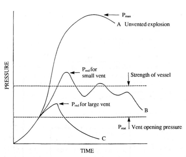
Explosion venting is a protective measure preventing unacceptable high explosion pressure build-up inside vessels / enclosures. Normally explosion venting is applied such that the maximum reduced explosion pressure (Pred,max) does not exceed the known design pressure of the vessel; the lower the vent opening pressure (Pstat) and the larger the vent area, the lower the reduced explosion pressure. Moreover, ALL parts of the enclosure, including valves, access ports, ductwork, etc. exposed to the explosion pressure, must be taken into account when estimating the design pressure of the vessel – this is to ensure that the relief of the explosion pressure is accomplished in a controlled manner.
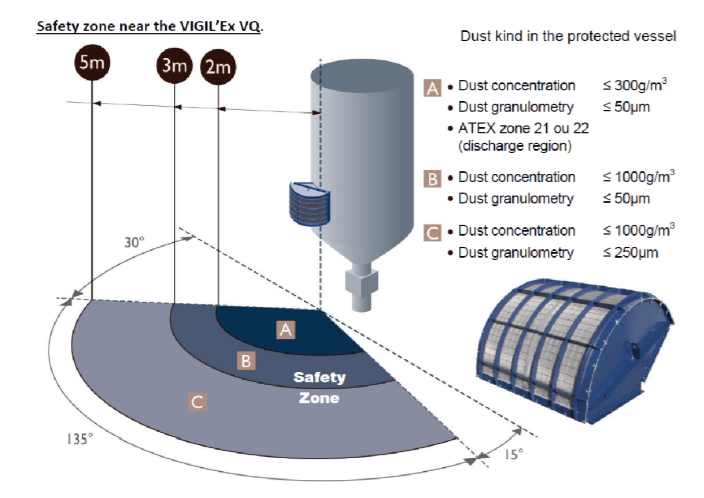
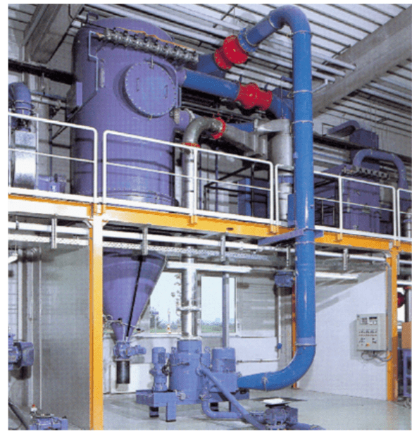
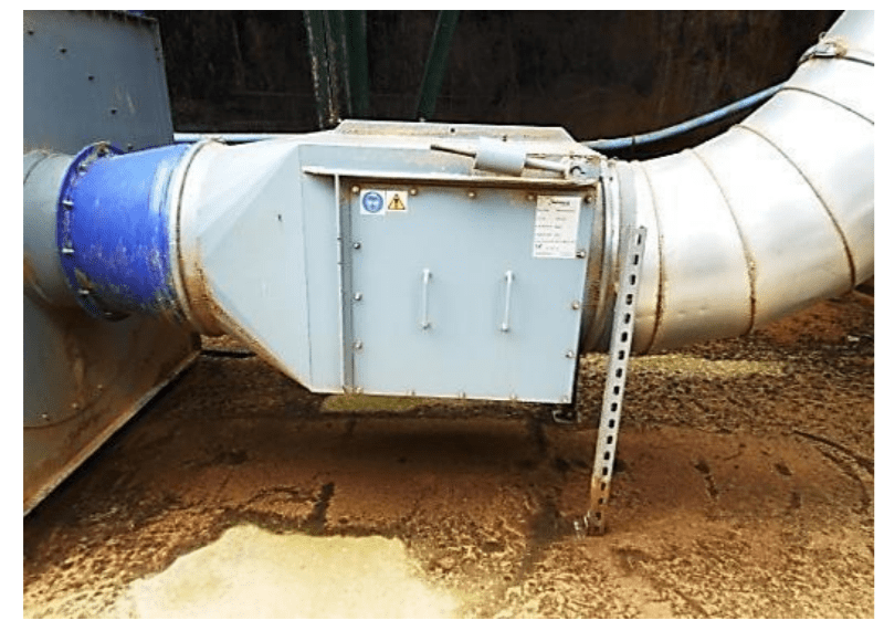
Venting does not prevent an explosion, it limits the explosion pressure. Hence, flame and pressure effects outside the enclosure and flying debris must be anticipated and accounted for. To preclude this, flameless venting devices (depicted below) may be used – this form of venting is particularly useful for plant sited in (or close to) the middle of the work area; otherwise, long vent ducts would be required to safely vent the explosion outside the confines of the building.
Explosion Supression
As mentioned above, explosion suppression does provide containment of the ‘reduced explosion pressure’ (Pred).
This is achieved by detection of the incipient explosion i.e. in its early stages. Whilst the combustion is taking place (most of the time quite rapidly over a few milliseconds), once detected, suppressant is injected in to the growing fireball to quench the flame.
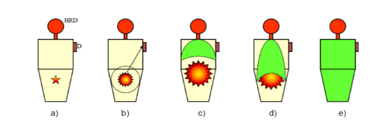
The predominant effect is absorption of heat, temperature reduction and stoppage of flame transmission. Once again, ALL parts / components of the vessel must be taken into account when estimating the design pressure.
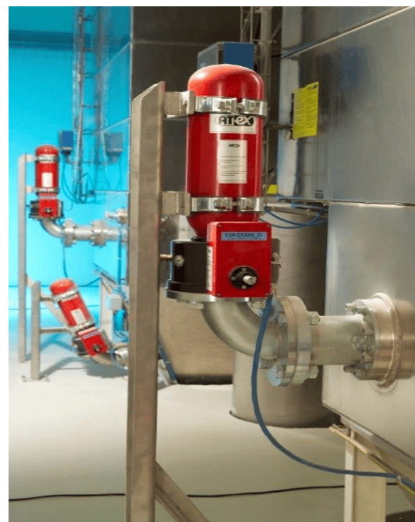
In practice, the quantity of suppressant (number of suppressors) and their location will depend on the violence of the explosion (Pred and Kst from dust testing), the geometry of the vessel and its design pressure.
Explosion Pressure Containment
With the exception of some milling operations, as a safety concept, explosion pressure containment is less common. This is due to the high design strength needed – typically of the order 8 – 10 bar.g for dust explosion containment. Common gases and hydrocarbons have lower peak explosion pressures of about 6 – 8 bar.g.
It is important to recognise, however, that ANY explosion protection system MUST cover upstream and downstream interconnections i.e. it is imperative to provide isolation to prevent propagation of burning particles, flame and pressure.
Isolation
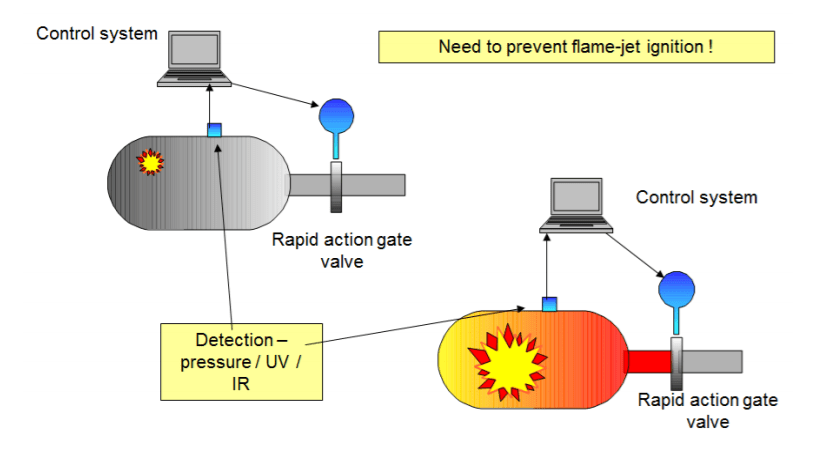
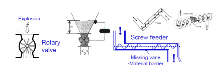
Isolation can take the form of an ATEX certified rotary valve or active of passive slam-shut (rapid action) valve, chemical extinguishing barrier, product choke, etc. as described in prEN 15089 Explosion Isolation Systems.
For complete isolation (e.g. by use of a slam-shut valve), the design pressure must be applied up to the isolation device. Hence, any ducting or pipework up to this point would need to withstand the maximum anticipated pressure i.e. Pred or Pmax. A typical arrangement is shown in the schematic below. The closure time of the rapid action valve, together with the response time of the detection/control system and flame speed, denes the required minimum distance (L) from the source of the explosion – typically L > 5000 mm.
A vented explosion must discharge to a safe area and often, this requires the use of a vent duct. The action of venting, in most cases, will be accompanied by ejection of burned and unburned gases and flames and measures must be taken to ensure that nearby plant and personnel will not be at risk from the vented fireball. It is important also to note that a vent duct will increase the backpressure during the relief process requiring a greater pressure resistance for equipment and vessels.
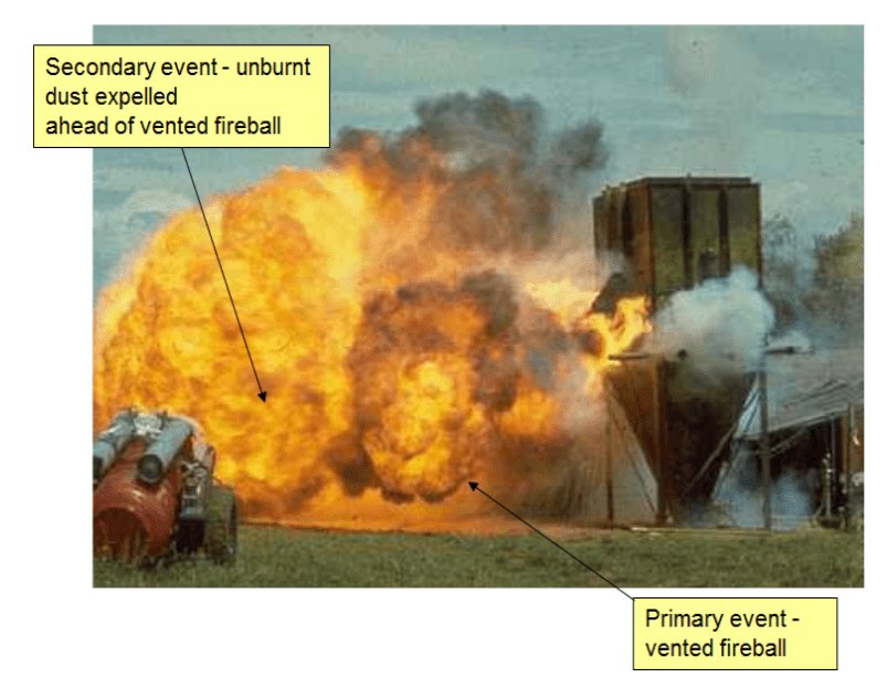
Flames ejecting from a vent opening will spread in all directions but especially in the main lateral venting direction due to inertia. Moreover, the flames will represent a thermal radiation hazard. In certain cases, a deflector plate (depicted below) can be used to limit the length of the ejected flame.
In addition, if the vent is situated in the side wall, the recoil force on the enclosure must be considered in the design. Also, as shown in the photograph above, unburned dust can be ejected ahead of the fireball during venting increasing external thermal radiation and overpressure effects.
As part of the isolation concept, equipment must be shut down automatically, in the event of an explosion, to prevent transfer of burning material, etc. With venting, this is normally achieved by sensors fitted to the vent panel. Of course, this should not result in frequent spurious shutdowns, since some will find ways of by-passing the problem – by means of wood and scaffolding poles to keep vent doors shut, for example, as shown. The CORRECT course of action would have been to examine why the explosion doors keep opening! When fitting explosion protection, from a process viewpoint, it is important to think about any repercussions. One example is the use of Rotary Valves for explosion isolation purposes as this is often contentious due to the likely ‘wear rates’ and the need to maintain certain tolerances (in particular, the gap between the blades and the casing).
Another example is the use of Flap-Valves in dust laden ductwork. The on-going ‘user obligations’ regarding inspection and maintenance of such items is not always appreciated.
For example, periodic inspection checks must be undertaken to ensure that the explosion isolation capability does not deteriorate (e.g. due to corrosion, abrasion, dust built up on the flap, dust build up inside the body of the flap valve).
The positioning of explosion vents on Dust Filters is important too, to ensure that the internal filter membranes do not obstruct (compromise) the protection.
Vent panels sited close to membranes can result in an increase in the ‘reduced explosion pressure’ (Pred value) and over-pressurisation of the vessel – the filter bags can be blown out of the vent on activation. A further consideration is that of providing automatic re suppression since Filters can be terminally damaged by secondary thermal stresses due to burning bags or product, following the explosion.
This is the seventh in a series of eight articles, which aim to help you establish a simple basis of safety in your plant and dispel some of the myths associated with process and safety risk assessments. The next article in the series is entitled ‘Management Procedures’ and covers the precautions we need to take as part of our managerial responsibilities to mitigate the risk of injury or fatality (to Plant Operators or members of the public), the Statutory Requirements (Legal Obligations) which we must adhere to and the consequences when things go wrong.
More Explosion Hazards Articles
- ATEX Safety | Establishing A Basis Of Safety In Explosive Atmospheres
- ATEX Safety | Characterising Material Hazards
- ATEX Safety | Hazardous Area Classification
- ATEX Safety | Potential Sources of Ignition
- ATEX Safety | Static Ignition & Thermal Instability
- ATEX Safety | Prevention
- ATEX Safety | Management Procedures

EXPERTS IN EQUIPMENT FOR EXPLOSIVE ATMOSPHERES
LEADERS IN ATEX INNOVATION TO THE HAZARDOUS AREA INDUSTRIES
Thorne & Derrick are leaders in the development and distribution of Product Innovations that deliver significant improvements to clients plant, people and operational safety in the explosive atmosphere industries.
Your proactive problem solvers experienced in succession planning for the replacement of obsolete, non-conformant and legacy equipment in hazardous areas.
Your first-choice provider of innovative and competitive solutions to ensure ATEX & IECEx Compliance for Hazardous Area Electrical, HVAC & Process Instrumentation Equipment to UK and international projects.
Control Panels | Plugs | Isolators | Enclosures & Junction Boxes | Lighting | Control Stations | Motor Starters | Heat Trace | Gas Detection | Flame Detection | Process Instrumentation | Process Heating | Ventilation Fans | Security Access Control

Competitive Prices | Extensive Stocks | Technical Support | Express Delivery