Marechal DSN24C Plugs – 24 Contacts 16A 415V IP66/67 Multi-Contact Connectors
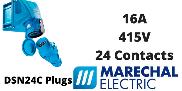
Marechal DSN24C Plugs – 24 Contacts 16A 415V IP66/67 Multi-Contact Connectors
Marechal DSN24C plugs and sockets are compact and watertight and have a rated current of 16A, a maximum voltage of 415V and up to 24 contacts. DSN24C plugs and sockets are automatically IP66/IP67 when connected and the socket outlet itself is also watertight when the lid is closed.
DSN24C connectors form part of the Marechal range of signal and control plugs – multicontact connectors (5 to 37) with waterproof electrical sockets to IP66/IP67 and IK08 IK09 protection for electrical equipment against external mechanical impacts.
Marechal DSN24C Plugs – Technical Specification
| Permitted Current Range | 4-20mA / 16A |
| Rated Current Per Contact (Max) | 16A |
| Total Current Carried | ≤ 230A |
| Maximum Voltage | 480V |
| Impulse Withstand Voltage | 5kV / Pollution degree 3 |
| Contact Resistance | < 2mΩ |
| IP Protection Lid Closed | IP66/IP67 |
| IP Protection Connected Plug | IP66/IP67 |
| Salt, Fog Performance | 200 hours minimum connected |
| Resistance To Fluids | Motor oils, petrol, fats, detergents |
| Butt Contacts | Female contacts: copper alloy silver plated / Male contacts: silver-nickel tips |
| Contact Protection | Silvering |
| Load Cycles | More than 5000 cycles |
| Vibration | Frequency 5-1000Hz, 1g / (90 minutes on each critical frequency) according to IEC 6068-2-6 |
| Shock Resistance | IK08 |
| Ambient Temperature | -40ºC to +60ºC |
| Flexible Wiring (Min-Max) | 1mm² – 2.5mm² |
| Wiring Terminals | Crimping |
| Keying Positions | 1 |
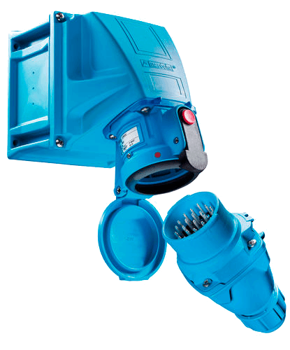
Marechal Connectors – DSN24C
Marechal DN24C Plug Polarity Options
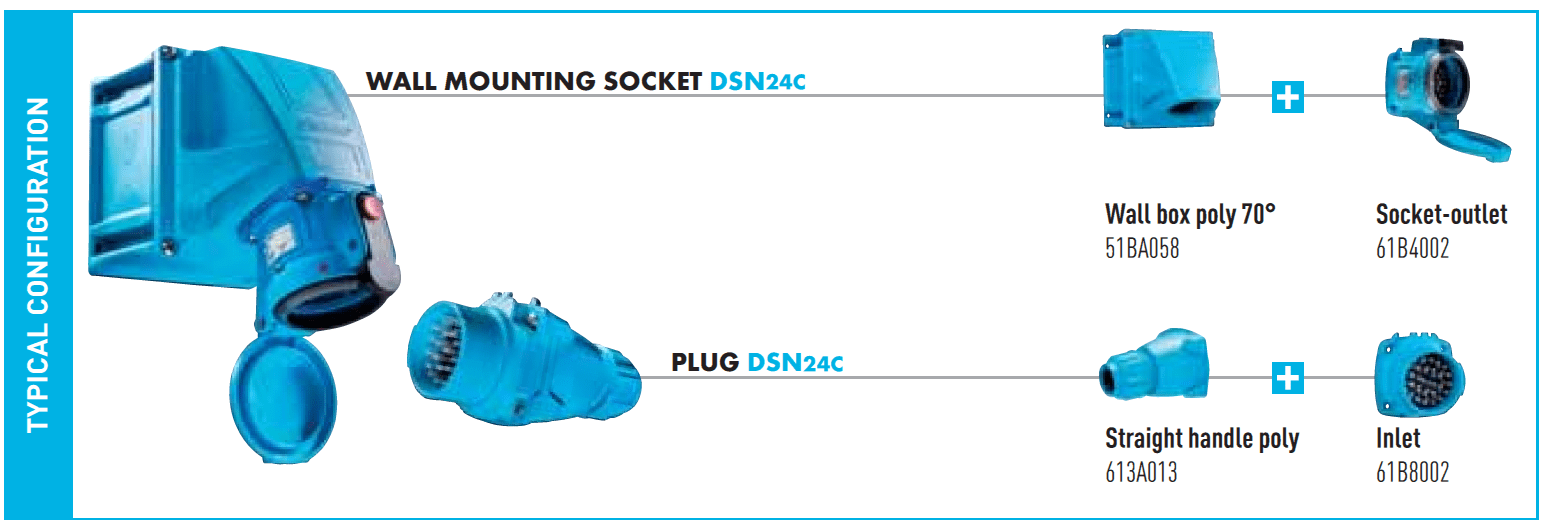
The DSN24C is available in GRP with 24 contacts for use with a maximum of 480V for both female socket outlets and male inlet plugs.
MARECHAL DSN24C CONNECTORS – SOCKET OUTLETS & INLET OPTIONS
| Umax | Contacts | Marechal Socket Outlet (Female) DN24C | Marechal Inlet (Male) DN24C |
| 480V | 24 contacts | 61B4002 | 61B8002 |
Marechal DN24C Plugs & Power Distribution Systems
Marechal DN24C decontactors (plug and socket outlets with integral power switch) are supported by an ancillary range of wall mounting sockets, wall boxes, socket outlets, sleeves, inlets and handles.

Handles

Boxes

Sleeves
Contact T&D To Discuss Technical Specifications For Marechal DN24C Plug-Sockets

Marechal DSN24C Plugs – Install & Operation Guide
Install & Operation Guidelines
- Install the socket-outlet facing downwards to prevent ingress of foreign bodies and the latch at the top to ease operation. See Figure C1. The latch can also be on the side in case of risk of accumulation of foreign bodies inside the cover.
- Install the appliance inlet as far as possible with the catch at the top to ease the operation of the connector. Connectors with lids opening at 180º may be used. See Figure C2. When this is not possible, install the inlet with the catch at the bottom. See Figure C3.
- Remove an adequate length of cable outer sheath according to the accessory used. Ensure that the cable sheathing extends through the cord grip into the handle or box as required to achieve the intended sealing and cord gripping performance.
- Strip the conductor insulation to the length indicated in Table T1.
- Fully insert the stripped conductor and its wiring lug (for conductors below 2.5mm²) into the contact hole;
- Crimp the contact with a KNIPEX crimping tool P/Nº 61CA500 or a GREENLEE crimping tool P/Nº 45505. Use the 4mm² footprint whatever the conductor cross-section. Perform a double crimping with a 90º rotation, in compliance with IEC 60352-2;
- Conductors can also be soldered: using tin solder and a 50W soldering iron, heat the terminal for approximately 30 seconds while heating, apply the soldering wire into the hole at the bottom of the terminal and let it penetrate by capillarity action. Let it cool down without any mechanical stress;
- Before wiring, equip each conductor with a heat-shrink sleeve or an insulating sleeve (bag of 13 pieces P/Nº 61CA083). Sleeving pliers (P/Nº 61CA400) are required to slip the insulating sleeve over the conductor:
- Slide the insulating sleeve up to the shoulder of the contact.
- Slide the heat-shrink sleeve up to the shoulder of the contact. With a heat gun, apply heat evenly 360º around the sleeve until it shrinks around the terminal and wire.
Figure F1:
A: Insulating sleeve or heat-shrink sleeve
B: Conductor
C: Retaining clip
D: Contact
If necessary, crimp the supplied Earth conductor in the Earth contact.
Contact Assembly / Disassembly – See Figure F2
Once wired, contacts must be inserted through through the rear of the interior moulding (1). Push each contact fully home. Check its proper engagement by a light pull (2). Contacts can be removed with the supplied tool: push the contact towards the front (3) and insert the tool through the front (4). Push the tool until the stop (5)
Figure F2:
D: Contact
E: Insulator
F: Tool
Self-Ejecting Devices
Tension Cord
The release of the latch is performed by a tension cord. One end of this cord must be attached either to the flexible cable or to a suitable fixed point of the installation. The other end is attached to the latch release mechanism.
Latch Release Mechanism
This mechanism comes in two different types:
- Ejecting Connector: The retaining latch is directly activated by the tension cord in case of traction (Figure E1)
- Ejecting Plug: A shark-fin mechanism (Figure E2) is assembled on the plug. It release the retaining latch of the socket-outlet in case of traction on the tension cord.
Eyelet
Handles are equipped with an eyelet. This eyelet allows an optimal pulling angle of the tension cord on the latch release mechanism. See Figure E3.
Assembly
The end of the tension cord that must be attached either to the flexible cable or to a suitable fixed point of the installation is equipped with a loop. A crimping ferrule is supplied to loop the other end of the cord, once it has been passed through the handle eyelet, the latch release mechanism, and cut to the adequate length. See Figure E3.
Cable Tie
A cable tie is supplied, to attach the loop of the tension cord onto the flexible cable.
Keyings
When 2 contacts are not used according to Table T2, nine keyings can be achieved by blanking two contact holes – socket-outlet/connector side – with two caps (supplied).
Sealing Rings
Insert a sealing ring between the device and its rear accessory (handle, angle, etc). The two protrusions of the rings must be positioned on the latch side for the socket-outlet/connector and on the catch side for the plug/appliance inlet. On self-ejecting plugs, the colour-coded ring is replaced by a flat gasket.
Operation
- The socket-outlet is shielded by a protective lid held in the closed position by a latch. Depress the latch to release the lid. See Figure F3.
- To connect, align the red marks on the housings. Insert the device and turn clockwise until the stop. The device is in the rest position, circuit open.
- Push the device fully home until latched.
- To disconnect, depress the latch. The device returns to its rest position.
- Turn the device in the opposite direction to remove it. Shut the lid.
➡ Read Blog: High Temperature Plugs For Critical Heat Resistant Applications

Visit Hazardous Area Plugs for Zone 1 & Zone 2 ATEX certified plugs and sockets for potentially explosive atmospheres.
Control Stations – Industrial & Hazardous Area (ATEX)
Control stations provide effective remote and local motor control with pushbuttons, visual indicators and circuit control – T&D stock an extensive range of pushbuttons, pilot lights and selector switches suitable for both hazardous and non-hazardous areas.
➡ Emergency Stop ♦ Emergency Power Off ♦ Emergency Stop/Start ♦ Stop Stations ♦ Start Stations ♦ Stop/Start Stations ♦ ATEX Certified ♦ Zone 1 & Zone 2 (Gas Vapour) ♦ Zone 22 Dust – see Hazardous Area Control Stations


