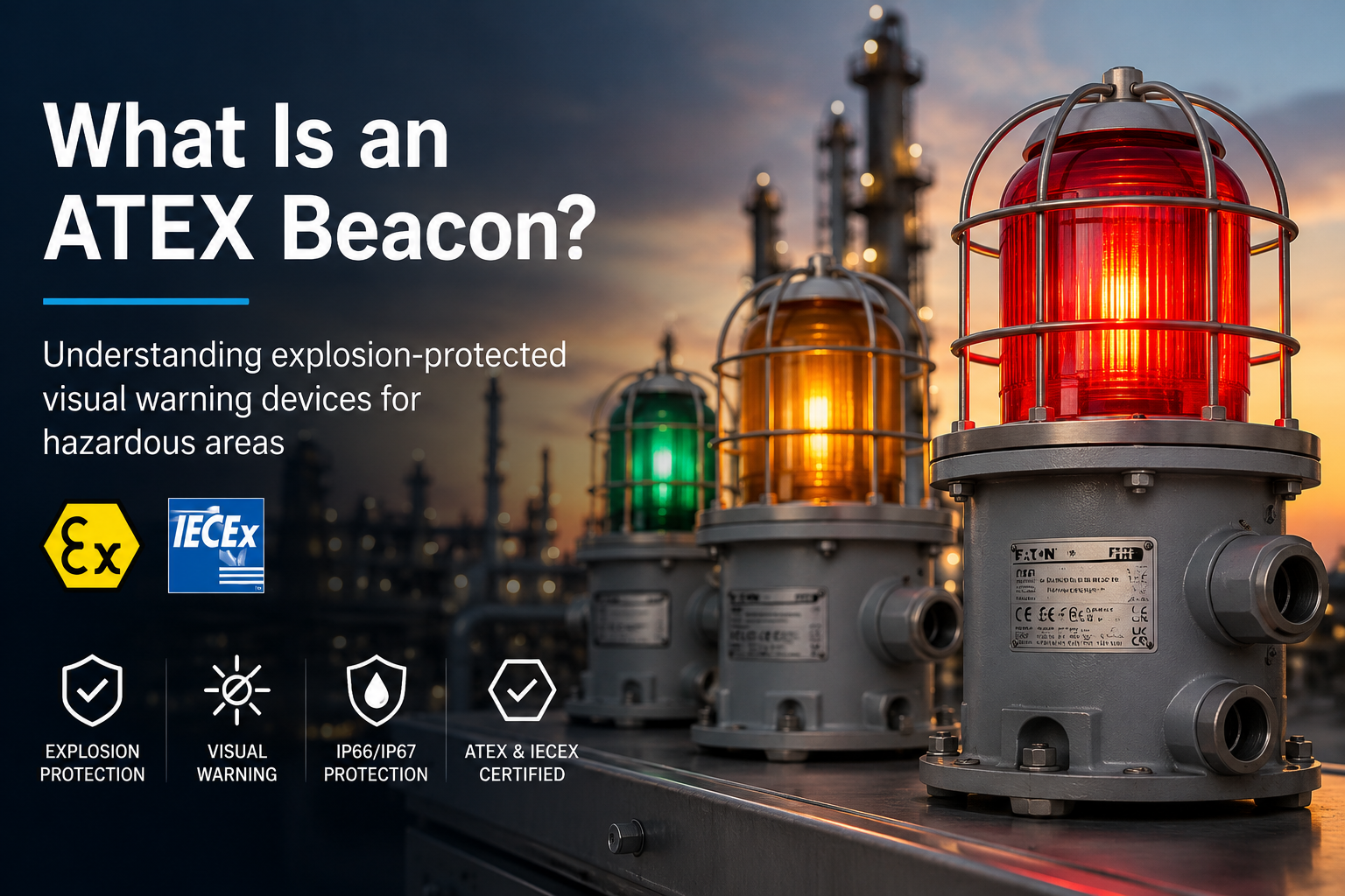
An ATEX beacon is a visual signalling device designed and certified for use where flammable gas, vapour, mist or combustible dust could create a potentially explosive atmosphere.
Depending on its design, the beacon may produce a steady, flashing, strobe, blinking or rotating visual signal. It can communicate an emergency alarm, evacuation condition, process event or equipment status without introducing unsuitable electrical equipment into the classified area.
Thorne & Derrick supplies a complete range of ATEX beacons with LED, xenon, steady-state, flashing and electronically rotating options for hazardous area signalling applications.
In brief: an ATEX beacon provides a visible warning or status signal while using a certified construction intended for a defined explosive atmosphere. Its complete certification and product marking must match the installation.
The purpose of an ATEX beacon is to provide a visible signal in a location where an ordinary industrial light or beacon may not be suitable.
The beacon does not normally detect gas, prevent a release or extinguish a fire. Instead, it communicates information generated by a fire and gas system, process-control system, emergency alarm, machine control or other monitoring equipment.
Typical applications include:
Warning personnel of a fire, gas release or emergency condition
Supporting evacuation or shelter-in-place alarms
Indicating a process fault, trip or shutdown
Showing machine, valve or equipment status
Providing a visible warning where high noise levels affect audible-alarm recognition
Distinguishing between different site conditions through signal patterns or lens colours
Visual signalling devices can operate independently or form part of a broader range of hazardous area sounders and beacons, including audible alarms, combination units, status lights and loudspeakers.
ATEX Beacon vs Ordinary Industrial Beacon
Both products may provide a similar visible warning, but their construction, testing and intended installation conditions are different.
Comparison
ATEX Beacon
Ordinary Industrial Beacon
Intended environment
Defined potentially explosive atmospheres
Non-classified industrial locations
Certification
Certified and marked for stated hazardous area conditions
Not necessarily certified for explosive atmospheres
Selection basis
Zone, atmosphere, group, temperature and protection concept
Voltage, light output, ingress protection and environment
Installation
Requires appropriate hazardous area installation practices
Standard industrial installation practices may apply
Why Does a Beacon Need Hazardous Area Certification?
Flammable gases, vapours, mists and combustible dusts can form an explosive mixture when combined with air. If this atmosphere encounters a sufficient ignition source, an explosion may occur.
Electrical equipment installed in a classified area must therefore be designed and selected to reduce the possibility of ignition.
Depending on the protection concept, this may involve containing an internal explosion, preventing ignition-capable sparks or temperatures, limiting electrical energy or preventing combustible dust from entering the enclosure.
The required approval can depend on the destination market, project specification and installation. ATEX, UKEX, IECEx and other regional approvals should not be treated as interchangeable without checking the applicable requirements.
Hazardous areas are classified according to the type of explosive atmosphere and how frequently it is expected to occur.
Gas, vapour and mist atmospheres use Zones 0, 1 and 2. Combustible-dust atmospheres use Zones 20, 21 and 22.
Zone
Atmosphere
General Definition
Zone 1
Gas, vapour or mist
An explosive atmosphere is likely to occur occasionally during normal operation.
Zone 2
Gas, vapour or mist
An explosive atmosphere is not likely during normal operation and, if it occurs, will normally exist only briefly.
Zone 21
Combustible dust
A combustible-dust atmosphere is likely to occur occasionally during normal operation.
Zone 22
Combustible dust
A combustible-dust atmosphere is not likely during normal operation and, if it occurs, will normally exist only briefly.
A beacon described as suitable for Zone 1 should not automatically be assumed suitable for every gas, combustible dust or temperature condition. Its complete product marking must match the hazardous area specification.
What Types of Hazardous Area Beacon Are Available?
LED Beacons
LED beacons use light-emitting diodes and may provide steady, flashing, blinking or electronically rotating signals. They are often selected where long operating life, defined signal patterns or reduced maintenance requirements are important.
Xenon Strobe Beacons
Xenon beacons use a xenon flash tube to produce a high-intensity visual pulse. They are commonly specified according to flash energy in joules, flash frequency, supply voltage and lens colour.
Steady Beacons
A steady beacon provides continuous visual indication. It may show a persistent warning, plant condition, equipment state or process status.
Rotating Beacons
Rotating beacons create a moving visual signal. Some use a mechanical rotating assembly, while others reproduce the effect electronically using sequenced LED segments.
Examples of Different Beacon Technologies
The following products illustrate steady, configurable LED and xenon-strobe signalling technologies.
No. “Explosion proof” is often used as a general search term, but equipment for explosive atmospheres can use several different protection concepts.
Ex d or Ex db flameproof: an enclosure is designed to contain an internal explosion and prevent flame propagation outside it.
Ex e or Ex eb increased safety: additional measures reduce the possibility of excessive temperatures, arcs or sparks during normal operation.
Ex ia intrinsic safety: electrical energy is limited to a level intended to prevent ignition under defined conditions.
Ex tb protection by enclosure: the enclosure helps prevent combustible-dust ingress and controls the maximum surface temperature.
Some products combine protection concepts. For example, the light chamber may use flameproof protection while the terminal compartment uses increased safety.
What Information Is Shown on the Beacon?
The product label and certification documents provide the information required to assess whether the equipment is suitable for a particular installation.
Depending on the product, its marking may identify:
Equipment group and category
Gas or combustible-dust suitability
Equipment protection level
Explosion-protection concept
Gas or dust group
Temperature class or maximum surface temperature
Permitted ambient-temperature range
Certificate number
Ingress-protection rating
Electrical supply and manufacturer information
The marking must be read as a complete specification. Selecting a product using only its zone number, ingress rating or product name is not sufficient.
Where Are Hazardous Area Beacons Used?
Visual signalling devices are used wherever an alarm or status indication is required within a classified environment.
Oil and gas production, processing and storage
Offshore platforms and marine installations
Refineries, petrochemical and chemical plants
Pharmaceutical and specialist manufacturing
Fuel terminals and distribution facilities
Grain, food and combustible-dust processing
Power generation and utilities
Water and wastewater treatment
How Is an ATEX Beacon Selected?
Product selection should begin with the hazardous area specification rather than the preferred manufacturer, colour or signalling technology.
Important selection criteria include:
Hazardous area zone
Gas, vapour, mist or combustible-dust atmosphere
Gas or dust group
Required protection concept and equipment category
Temperature class and ambient-temperature range
LED, xenon, steady, flashing, strobe or rotating signal
Required light intensity, flash energy and viewing distance
Operating voltage and control arrangement
Lens colour and site alarm philosophy
Ingress protection, enclosure material and corrosion exposure
Indoor, outdoor, offshore or marine installation conditions
Required regional and project approvals
Hazardous Area Beacon Selection Support
Send Thorne & Derrick the hazardous area classification, required signal type, operating voltage, lens colour and installation conditions for product selection support.
ATEX is the name commonly used for the European framework relating to equipment and protective systems intended for use in potentially explosive atmospheres.
What is the difference between a Zone 1 and Zone 2 beacon?
The difference relates to the classified area and the expected frequency of an explosive gas atmosphere. The beacon must carry certification suitable for the specified zone and complete application.
Can the same beacon be used for gas and dust?
Only when the product carries the required certification and markings for both the gas and combustible-dust application.
Is an ATEX beacon always flashing?
No. Hazardous area beacons can provide steady, flashing, strobe, blinking, mechanically rotating or electronically rotating signals, depending on the product.
Do beacon lens colours have fixed meanings?
The intended meaning should be defined by the site alarm philosophy or project specification. It should not be assumed from the lens colour alone.
Can a beacon connect to a fire or gas detection system?
Many models can be integrated into wider alarm and control systems. Compatibility must be checked against the supply voltage, current, control method, certification and overall system design.
Compare Hazardous Area Visual Signalling Devices
Explore LED, xenon, steady, flashing and rotating signalling options for Zone 1, Zone 2, Zone 21 and Zone 22 installations.
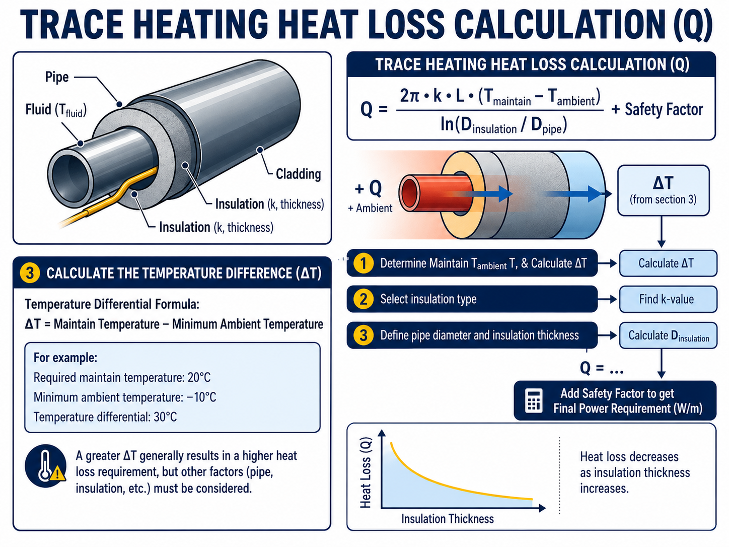
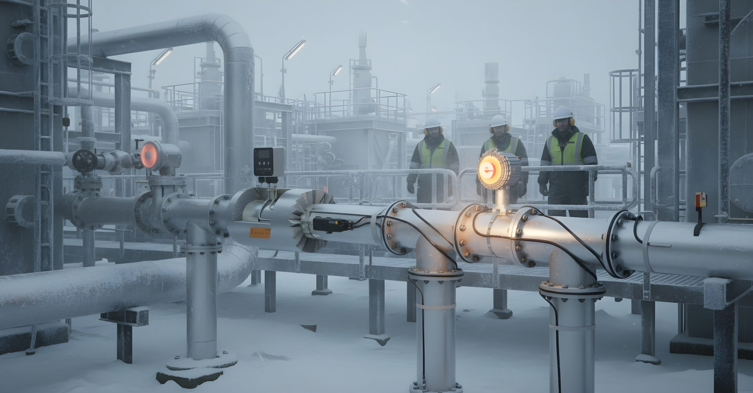
A trace heating heat loss calculation determines how much electrical heating power is required to compensate for heat escaping from insulated pipework, tanks, vessels or process equipment. The result is normally expressed as watts per metre and provides the starting point for selecting the appropriate heating cable, controls and circuit arrangement.
Before completing a heat-loss calculation, it is useful to understand how electrical trace heating works and how the cable compensates for heat escaping from pipework or equipment.
The purpose of the calculation:
Establish the heat being lost from the insulated surface
Determine the heating output required in watts per metre
Support the selection of a suitable heating cable technology
Confirm the total system load and circuit arrangement
Inform the selection of controls, sensors and connection components
Why Is a Trace Heating Heat Loss Calculation Required?
A trace heating system must produce enough heat to offset the heat being lost from the surface being protected.
When the heating cable output matches the system heat loss, the pipe, vessel or equipment can be maintained at the required temperature. If the cable output is too low, the system may fail to prevent freezing or maintain the required process temperature.
Selecting substantially more output than necessary can also create problems, including:
Increased energy consumption
Higher electrical loads
Unnecessary control cycling
Excessive surface temperatures
Increased project and operating costs
Potential damage to temperature-sensitive pipework or products
A reliable electrical heat tracing calculation therefore supports cable selection, circuit design, temperature control and long-term system performance.
Heat Loss Design Inputs
Accurate temperature, pipework, insulation and environmental data is required before heating cable output can be selected.
What Information Is Needed for a Pipe Heat Loss Calculation?
The quality of the calculation depends on the accuracy of the information supplied. Making assumptions about temperatures, insulation or pipe dimensions can result in an unsuitable cable being specified.
Design Information
Why It Is Required
Required maintain temperature
Establishes the temperature the system must protect or maintain
Minimum ambient temperature
Defines the coldest expected surrounding condition
Pipe outside diameter
Influences the surface area through which heat is lost
Pipe material
Affects heat transfer, heat distribution and permissible surface temperatures
Pipe length
Determines total cable requirement and electrical load
Insulation material
Different insulation materials have different thermal properties
Insulation thickness
Thicker insulation will generally reduce heat loss
Indoor or outdoor location
Outdoor systems may face greater environmental exposure
Maximum wind speed
Increased airflow can increase heat loss from outdoor systems
Maximum process temperature
Helps confirm cable temperature suitability
Operating voltage
Influences cable and circuit selection
Valves, flanges and supports
These can create additional local heat-loss requirements
Area classification
Determines whether safe-area or hazardous-area equipment is required
Required heat-up time
May require a separate start-up heating calculation
1. Confirm the Required Maintain Temperature
The maintain temperature is the minimum pipe, product or equipment temperature that the trace heating system is required to preserve.
This should not automatically be assumed to be the normal process temperature. The required value depends on the purpose of the system.
Frost Protection
For frost protection, the maintain temperature must keep the water or process fluid safely above its freezing point under the specified design conditions.
The material being protected
The concentration or composition of the fluid
Whether the pipe is continuously flowing or static
The consequence of freezing
Site or project specifications
Any required operating margin
Process Temperature Maintenance
For process maintenance, the temperature may need to keep a product:
Pumpable
Flowable
Above its crystallisation temperature
Below a viscosity limit
Within a specified processing range
Ready for transfer or production
Oils, waxes, chemicals, resins, bitumen and food products can all have different temperature-maintenance requirements. The selected value should be confirmed by the process engineer or end user rather than estimated solely from normal operating conditions.
2. Establish the Minimum Ambient Temperature
The minimum ambient temperature is the lowest surrounding temperature at which the trace heating system is expected to maintain the required pipe or equipment temperature.
This value should reflect the actual site and installation conditions.
Historical minimum temperatures
Local weather data
Site elevation
Exposed or sheltered position
Offshore or coastal conditions
Refrigerated or cold-room environments
Unheated buildings
Roof spaces and external service areas
Wind exposure
Project-specific design temperatures
Using an annual average temperature would not represent a worst-case frost protection or process maintenance condition.
3. Calculate the Temperature Difference
The difference between the required maintain temperature and the minimum ambient temperature is commonly shown as ΔT, or temperature differential.
Temperature Differential Formula
ΔT = Maintain Temperature − Minimum Ambient Temperature
For example:
Required maintain temperature: 20°C
Minimum ambient temperature: −10°C
Temperature differential: 30°C
A greater temperature differential normally results in a greater heat-loss requirement. However, the temperature differential is not the complete heat-loss calculation. Pipe dimensions, insulation, environmental conditions and other design factors must also be considered before the required watts per metre can be established.
4. Record the Pipe Diameter and Material
The outside diameter of the pipe affects the surface area through which heat can escape. A larger pipe will normally lose more heat per metre than a smaller pipe under otherwise identical conditions.
The actual outside diameter should be confirmed rather than estimated from the nominal pipe description, particularly where:
Non-standard pipework is used
The line includes different pipe sizes
Tubing is being heated
The system contains reducers
The pipe has an external coating
Existing insulation is being replaced
The pipe material should also be recorded. Common materials include carbon steel, stainless steel, copper, plastic, composite and glass-lined pipework.
Metal pipes generally distribute heat effectively around their circumference. Plastic and other temperature-sensitive pipes may require additional design measures to spread heat and prevent excessive local surface temperatures.
5. Confirm the Insulation Material and Thickness
Thermal insulation reduces the rate at which heat escapes from the pipe or equipment. It is therefore one of the most influential parts of a heat loss calculation for pipework.
Two items must be confirmed:
The insulation material
The insulation thickness
Different insulation materials can have different thermal conductivity values. Two systems with the same pipe diameter and insulation thickness may therefore produce different heat-loss results if the insulation materials differ.
Common insulation materials include:
Mineral wool
Glass fibre
Cellular glass
Calcium silicate
Phenolic insulation
Polyurethane insulation
Elastomeric insulation
Damaged, compressed or waterlogged insulation may not provide its original thermal performance. Where an existing installation is being upgraded, the insulation condition should be assessed rather than relying only on its original specification.
6. Account for Indoor, Outdoor and Weather Conditions
The same pipe may have a different heat-loss requirement depending on where it is installed.
An indoor pipe in a controlled environment is usually exposed to less severe conditions than pipework installed:
Outdoors
On an exposed structure
On a rooftop
Offshore
In a coastal environment
Within an open-sided building
In an area subject to high wind speeds
Wind can increase heat transfer from the outer surface of the insulated system. Outdoor calculations may therefore include an adjustment for the specified maximum wind speed and installation conditions.
The insulation should also be protected by suitable weatherproof cladding. Water ingress can reduce insulation performance and increase the heat that the trace heating system must replace.
7. Include Valves, Flanges, Supports and Other Heat Sinks
A straight pipe heat-loss calculation does not always represent the complete system.
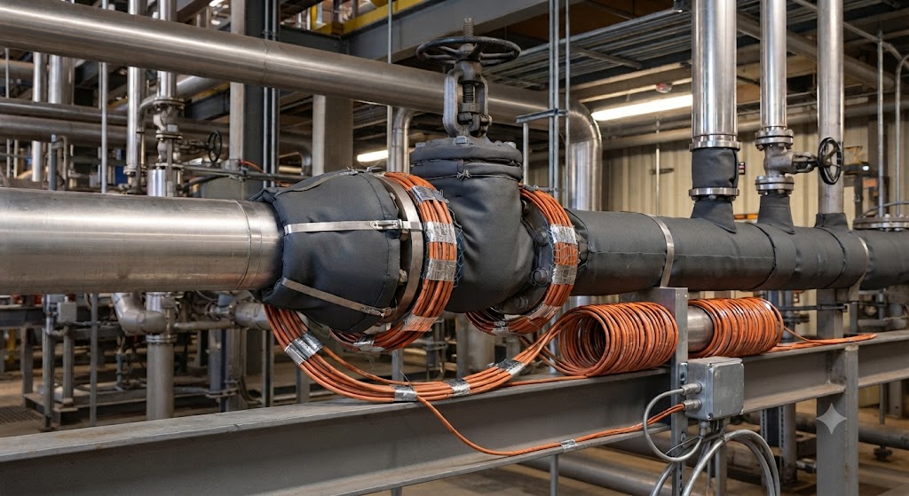
Valves, flanges, pumps, supports and other in-line equipment can have a larger exposed surface area or greater thermal mass than the adjoining pipe. They may therefore require additional heating cable or a specific cable installation arrangement.
Valves
Flanges
Pumps
Pipe shoes
Supports and hangers
Strainers and filters
Instruments and sample lines
Branch connections
Drain points
Expansion joints
The allowance should be based on the relevant manufacturer’s design method and installation details. A standard percentage should not automatically be applied to every system because the quantity, dimensions and construction of the components can vary considerably.
Allow for Local Heat Sinks
Valves, flanges and supports may require additional cable or a specific installation arrangement.
8. Apply an Appropriate Design Allowance
A trace heating design may include an allowance for uncertainties such as:
Minor variations in insulation
Installation tolerances
Environmental exposure
Ageing of the system
Differences between design and actual site conditions
Small variations in voltage or cable performance
This allowance should be applied using the selected manufacturer’s design methodology or the requirements of the project specification.
Important Design Note
An excessive allowance should not be used as a substitute for accurate design information. Increasing cable output without considering maximum surface temperature, control requirements and electrical loading can result in an inefficient or unsuitable system.
9. Establish the Required Trace Heating Cable Output
Once the adjusted heat loss has been calculated, the result is normally expressed in:
Watts per metre, or
Watts per foot
The selected cable must provide sufficient output to compensate for the calculated loss at the required maintain temperature and design conditions.
This is important because the nominal value used in a product name or data sheet may be stated at a particular reference temperature. The actual output available at the required pipe temperature must be checked using the manufacturer’s performance data or design software.
When the surrounding temperature falls, the cable can produce more heat. As the temperature rises, its output reduces. The relevant output at the design maintain temperature must therefore be confirmed from the manufacturer’s output curves or calculation software.
Cable output, maximum exposure temperature, circuit length, control requirements and installation arrangement must all be checked against the application.
Mineral-Insulated Heating Cables
Mineral-insulated cables may be selected for high-temperature, high-output or demanding industrial applications.
These systems are normally engineered for the individual application and require careful calculation of cable resistance, circuit length, supply voltage, operating temperature and maximum sheath temperature.
Thorne & Derrick supplies an extensive heat trace cable range for frost protection, process temperature maintenance and industrial heating applications.
Does Pipe Length Affect the Heat Loss Per Metre?
Under uniform conditions, increasing the pipe length does not necessarily change the calculated heat loss per metre.
If every part of a straight pipe has the same diameter, maintain temperature, insulation, ambient temperature and exposure conditions, the heat loss per metre may remain consistent.
However, increasing the pipe length increases:
Total system heat loss
Required cable length
Total electrical load
Number or length of circuits
Quantity of connection components
Potential voltage-drop considerations
Starting-current requirements
Long pipe runs may also contain changes in pipe diameter, insulation, temperature requirement or area classification. These sections may need to be calculated and circuited separately.
Heat Maintenance Versus Heat-Up Duty
A standard heat-loss calculation usually establishes the power required to maintain a pipe or product at a specified temperature.
It does not necessarily calculate the additional energy required to raise a cold pipe and its contents to that temperature within a defined period.
Where start-up heating is required, additional information may include:
Initial pipe and product temperature
Final required temperature
Volume of the product
Product density
Specific heat capacity
Pipe wall material and thickness
Required heat-up time
Additional heat lost during warm-up
A system designed only to replace steady-state heat loss may maintain temperature effectively but take a long time to heat cold process contents.
Heat Loss Calculations for Tanks and Vessels
The same general principles apply when calculating heat loss from tanks, vessels, hoppers and other equipment, but the required inputs are different.
Total exposed surface area
Tank shape and dimensions
Tank material
Insulation material and thickness
Minimum ambient temperature
Required maintain temperature
Wind speed
Fluid volume and properties
Required heat-up time
Supports, legs and nozzles
Uninsulated surfaces
Tank and vessel calculations should not be based solely on a pipe heat-loss table. The surface area, construction and start-up requirements can have a substantial influence on the total heating duty.
What Happens After the Heat Loss Has Been Calculated?
The heat-loss result is only one part of the complete electrical heat tracing design.
Select the heating cable technology
Confirm cable output at the design temperature
Determine the number of cable runs
Calculate the total cable length
Check maximum circuit lengths
Establish operating and starting currents
Select electrical protection
Select thermostats, controllers and sensors
Select power connections and termination kits
Confirm environmental and hazardous-area approvals
Produce cable schedules and circuit documentation
Prepare the bill of materials
For hazardous-area applications, the design must also consider the area classification, equipment protection level, temperature classification, maximum cable temperature and certification of the complete system.
Why Use Specialist Heat Trace Design Software?
Simple tables and calculators can provide an initial estimate, but detailed systems should be designed using suitable manufacturer software and verified by a competent trace heating specialist.
Specialist design software can account for:
Multiple pipe sizes
Different insulation specifications
Cable performance at temperature
Maximum circuit lengths
Starting and operating currents
Supply voltage
Control and monitoring requirements
Connection components
Hazardous-area requirements
Total connected load
Bills of materials
Manufacturer software is used to match calculated heat loss with a specific cable, connection system and temperature-control arrangement rather than selecting a product solely from its nominal watts-per-metre rating.
Information to Provide for a Trace Heating Calculation
Providing the following information will support an accurate calculation and quotation:
Application Details
Frost protection or process maintenance
Description of the product or fluid
Required maintain temperature
Minimum ambient temperature
Maximum process or exposure temperature
Required heat-up time, where applicable
Pipework Details
Pipe material
Outside diameter
Pipe length
Number and size of valves
Number and size of flanges
Quantity of supports
Branches, pumps and other equipment
Insulation Details
Insulation material
Insulation thickness
External cladding material
Condition of existing insulation
Electrical and Site Details
Available voltage
Preferred power-supply locations
Existing circuit limitations
Control and monitoring requirements
Indoor or outdoor installation
Minimum site temperature
Maximum wind exposure
Safe-area or hazardous-area classification
Gas or dust group, where applicable
Required temperature class
Corrosive or chemically aggressive conditions
Common Trace Heating Calculation Mistakes
Using the normal ambient temperature instead of the minimum design temperature
Confusing process temperature with the required maintain temperature
Estimating the insulation specification
Ignoring valves and flanges
Selecting cable from its nominal output alone
Failing to check output at the maintain temperature
Omitting maximum process or steam-cleaning temperatures
Ignoring circuit-length limitations
Assuming all pipework has the same diameter and insulation
Failing to distinguish maintenance duty from heat-up duty
Treating hazardous-area certification as a cable-only requirement
Selecting cable before the heat loss is known
Accurate project data helps reduce redesign, avoid unnecessary cable output and improve the reliability of the finished system.
Trace Heating Heat Loss Calculation FAQs
Can Trace Heating Cable Be Selected from the Pipe Diameter Alone?
No. Pipe diameter is only one design input. The maintain temperature, minimum ambient temperature, insulation type, insulation thickness, environmental conditions and application requirements must also be considered.
Does Thicker Insulation Reduce the Required Heating Cable Output?
Generally, yes. Increasing the insulation thickness can reduce heat loss, provided the insulation is correctly selected, installed, dry and protected. The actual reduction will depend on the insulation material, pipe diameter and operating temperatures.
Is the Highest Available Watts-Per-Metre Cable the Safest Choice?
Not necessarily. Excessive output can increase electrical loads, operating costs and surface temperatures. The selected cable should provide sufficient output to compensate for the calculated heat loss while remaining suitable for the pipe material, process temperature, area classification and control system.
Do Valves and Flanges Need Additional Heating Cable?
They commonly require an additional allowance because they can lose more heat than an equivalent length of straight insulated pipe. The cable arrangement and allowance should follow the heating cable manufacturer’s design and installation guidance.
Can a Heat-Loss Calculator Replace a Complete Trace Heating Design?
No. A heat-loss calculator may estimate the required watts per metre, but the complete system design must also consider cable performance, circuit lengths, starting current, electrical protection, controls, accessories, installation conditions and area classification.
Are Additional Design Checks Required for Hazardous Areas?
Yes. The thermal calculation still establishes the required heating output, but hazardous-area systems require additional checks covering equipment certification, area classification, maximum surface temperature, temperature class and the suitability of the heating cable, controls and connection components.
Need a Trace Heating Heat Loss Calculation?
Thorne & Derrick is an experienced supplier of electrical heat tracing systems, heating cables, controls and connection components for commercial, industrial and hazardous-area applications.
In-house heat-loss calculations
Trace heating cable selection
Electrical system design
Cable and circuit schedules
Temperature-control specification
Hazardous-area product selection
Complete bills of materials
Technical support for frost protection and process maintenance
Provide the pipework, temperature, insulation and site information to our team, and we can help develop a trace heating system suited to the application.
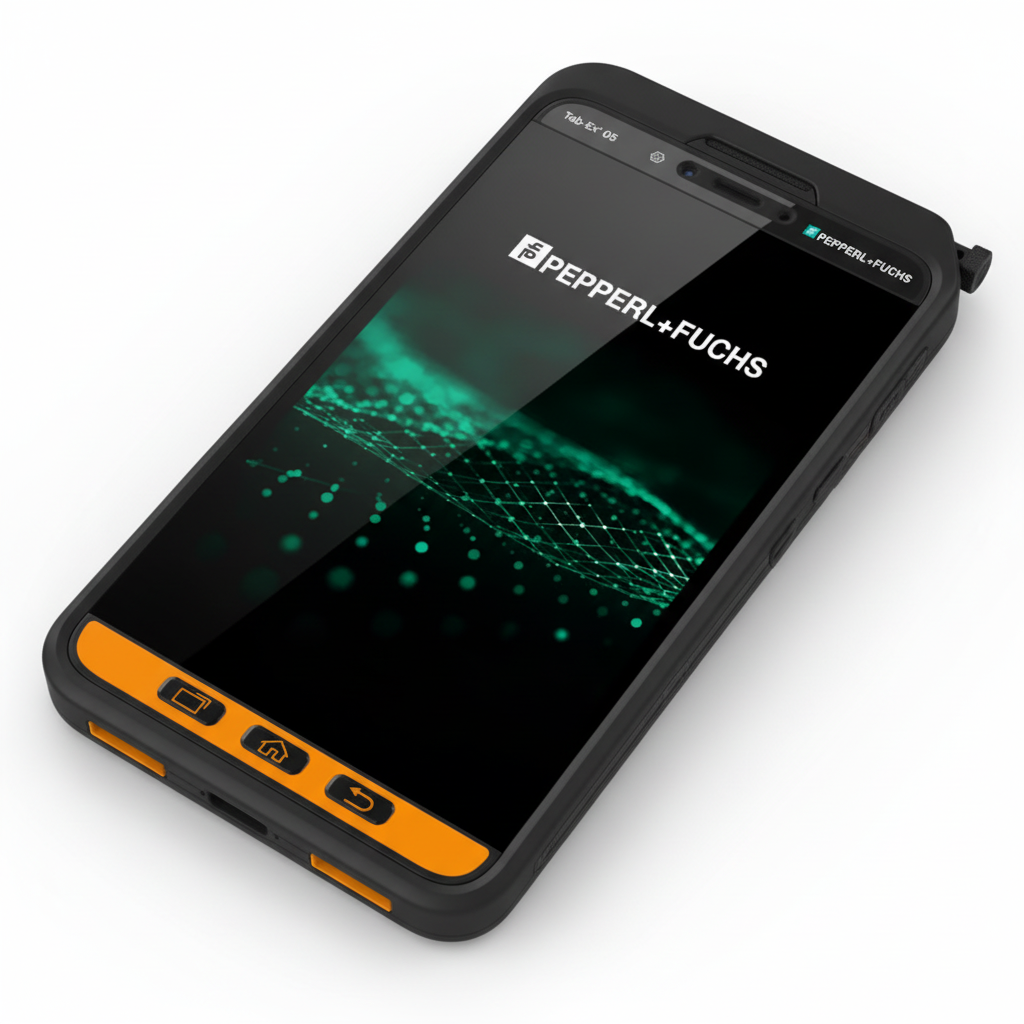
Thorne & Derrick is pleased to reaffirm its distribution partnership with Pepperl + Fuchs, with a renewed focus onEnterprise Mobility solutions for hazardous area and industrial applications. This includes rugged ATEX mobile phones and ATEX tablets designed to support safe communication and digital workflows in environments where standard consumer devices are not suitable.
The partnership brings together two complementary strengths. Pepperl + Fuchs is globally recognised for its innovation, product quality and certified solutions for demanding industrial environments, while Thorne & Derrick provides specialist distribution, market knowledge and application support to help customers source the right products with confidence.
By working closely together, both businesses are well placed to improve customer access to key product ranges, strengthen product visibility in the market and support safer, more effective operations across hazardous area applications.
WORKING TOGETHER
This renewed focus is already being supported by practical activity across both sales and marketing. Recent product training has helped strengthen understanding across the team, while wider work is underway to improve visibility across key Pepperl + Fuchs product areas online.
For Thorne & Derrick, this is about more than promoting individual products. It reflects a wider commitment to helping customers access trusted, compliant solutions backed by informed support, stronger product visibility and a better route to specification and supply.
What This Means for Customers
Improved access to certified hazardous area communication devices
Stronger specialist support for product selection and application guidance
Greater visibility across key Pepperl + Fuchs product ranges
Continued investment in training, content and customer support
A stronger route to market for hazardous area and industrial solutions
Terry McDonald, Sales & Business Development Manager at Thorne & Derrick, commented:
“Pepperl + Fuchs is a highly respected name in hazardous area technology, and this partnership reflects our shared commitment to supporting customers with trusted products, practical guidance and responsive service. By working closely together, we are well placed to strengthen awareness of the range and help customers identify the right solutions for their applications.”
Karen Jarrett, Team Lead UK and Ireland at Pepperl + Fuchs, added:
“Thorne & Derrick brings strong market understanding and a clear focus on supporting customers in hazardous area applications. We are pleased to continue working together and to build on a partnership that helps improve access to Pepperl + Fuchs solutions across key industrial sectors.”
Pepperl + Fuchs ATEX Mobile Phones & Tablets
A particular area of focus is Pepperl + Fuchs Enterprise Mobility, including ATEX mobile phones and ATEX tablets for hazardous area and industrial applications.
These devices support safe communication and digital workflows in environments where standard consumer technology is not suitable, helping operators work more effectively across sectors such as oil & gas, chemical processing, petrochemical, pharmaceutical, utilities, energy and wider industrial processing.
Ideal for: oil & gas, petrochemical, chemical processing, pharmaceutical manufacturing, energy, utilities and other hazardous industrial sectors.
ATEX Mobile Phones
Certified hazardous area smartphones for safe communication in Zone 1, Zone 2 and other hazardous industrial environments.
Alongside this strengthened partnership, Thorne & Derrick is continuing to invest in refreshed product content, improved online visibility and wider support across key Pepperl + Fuchs categories.
With particular focus on ATEX mobile phones and ATEX tablets, the aim is to make it easier for customers to access rugged, certified communication devices backed by specialist support.
Thorne & Derrick looks forward to building further on its relationship with Pepperl + Fuchs and supporting customers with trusted hazardous area solutions for demanding industrial environments.
Pepperl + Fuchs
Pepperl + Fuchs is a global manufacturer of industrial technology and hazardous area equipment, including rugged Enterprise Mobility devices for certified communication in explosive atmospheres and demanding industrial environments.
Thorne & Derrick supplies Pepperl + Fuchs hazardous area mobile & tablet devices to UK and international customers, supporting safe specification and supply across demanding industrial environments.
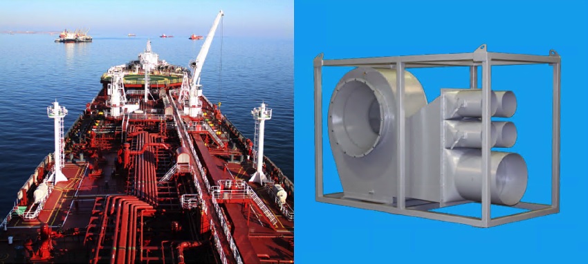
Fixed & Portable ATEX Fans
ATEX & IECEX Fans
Fixed & Portable Tank Ventilation Solution For Hazardous Areas
Thorne & Derrick distribute a range of cost effective ATEX fans offering a high performance fixed and portable tank ventilation solution for hazardous areas and explosive atmospheres. Suitable for confined space applications where fresh air is required to provide a safe working environment and for gas freeing of oil and chemical tanks.
These ATEX & IECEx fans can be fully portable so can be used on a wide range of vessels. Safety is paramount nowadays particularly in the workplace and the Tank Vent ATEX Portable Fan range provides fresh air when entry into a confined space for workers in tank cleaning is unavoidable.
Thorne & Derrick can provide a portable, electrically driven unit to provide fresh air for the safety of workers and of the vessels while cleaning of storage holds and tanks takes place.
These units can be independently ATEX and/or IECEx Certified and are certified to both Electrical & Non-Electrical standards for safe ventilation of hazardous area workplaces and potentially explosive atmospheres – providing a world wide safety solution.
ATEX & IECEx fans continuously move fresh, uncontaminated air through a hazardous area as an effective means of controlling an atmospheric explosive hazard.
Currently Thorne & Derrick distribute the following ATEX & IECEx Fans Approved for Ventilation of Explosive Atmospheres:
The following check-list provides information to clients to ensure their ventilation fans are safe and compliant with ATEX and IECEx requirements for service in potentially explosive atmospheres and hazardous area locations.
Hazardous area certification must show compliance to BS EN 14986: 201
Beware of product only using the certification from the electrical equipment. ATEX covers both mechanical and electrial equipment.
Dedicated ATEX documentation with regard to operation, installation and maintenance
Clearances between rotating elements and fan casing
Rigid impeller construction with over-speed capacity
Thorne & Derrick International distribute an extensive range of ATEX & IECEx Certified Productsfor safe use in Potentially Explosive Atmospheres & Hazardous Areas– these products help overcome the dangers of confined space working alleviating risks with the provision of certified and safe confined space lighting, power, heat and ventilation – keeping workers safe during maintenance, repair and installation works in hazardous area locations in potentially explosive atmospheres.
The Exstream range of 3rd Party Certified Portable Fans distributed by Thorne & Derrick are independently dual certified IECEx & ATEX portable ventilation fans certified to both Electrical & Non-Electrical standards to provide a world wide safety solution.
On 6 July 1988, the Piper Alpha disaster claimed the lives of 167 men in the North Sea.
For many, it is a moment in history. For others, it hits much closer to home.
Terry McDonald’s father worked offshore, so when news of the disaster began to spread and people started ringing the house that night, the uncertainty and fear were very real. His father was not working on Piper Alpha, but the event still left a lasting impression and a stark reminder of how devastating failures in hazardous environments can be.
Fast forward to today, and Terry now works for a company supplying equipment into hazardous areas, continuing to campaign for better awareness, better decision-making, and stronger vigilance around Fake ATEX / non-compliant equipment.
That is exactly why we launched this initiative – to help raise awareness before failure forces change, and to reinforce that hazardous area safety depends not only on engineering disciplines, but on everyone involved in specification, procurement, support, and site operations.
Because the lesson from Piper Alpha is not just about what happened. It is about what should happen next.
Key Message:
Safety improvement should not only come after disaster
Awareness must reach beyond engineering roles
Procurement, specification, and decision-making all influence risk
Knowledge and vigilance help prevent non-compliant equipment entering site
Initiative Overview
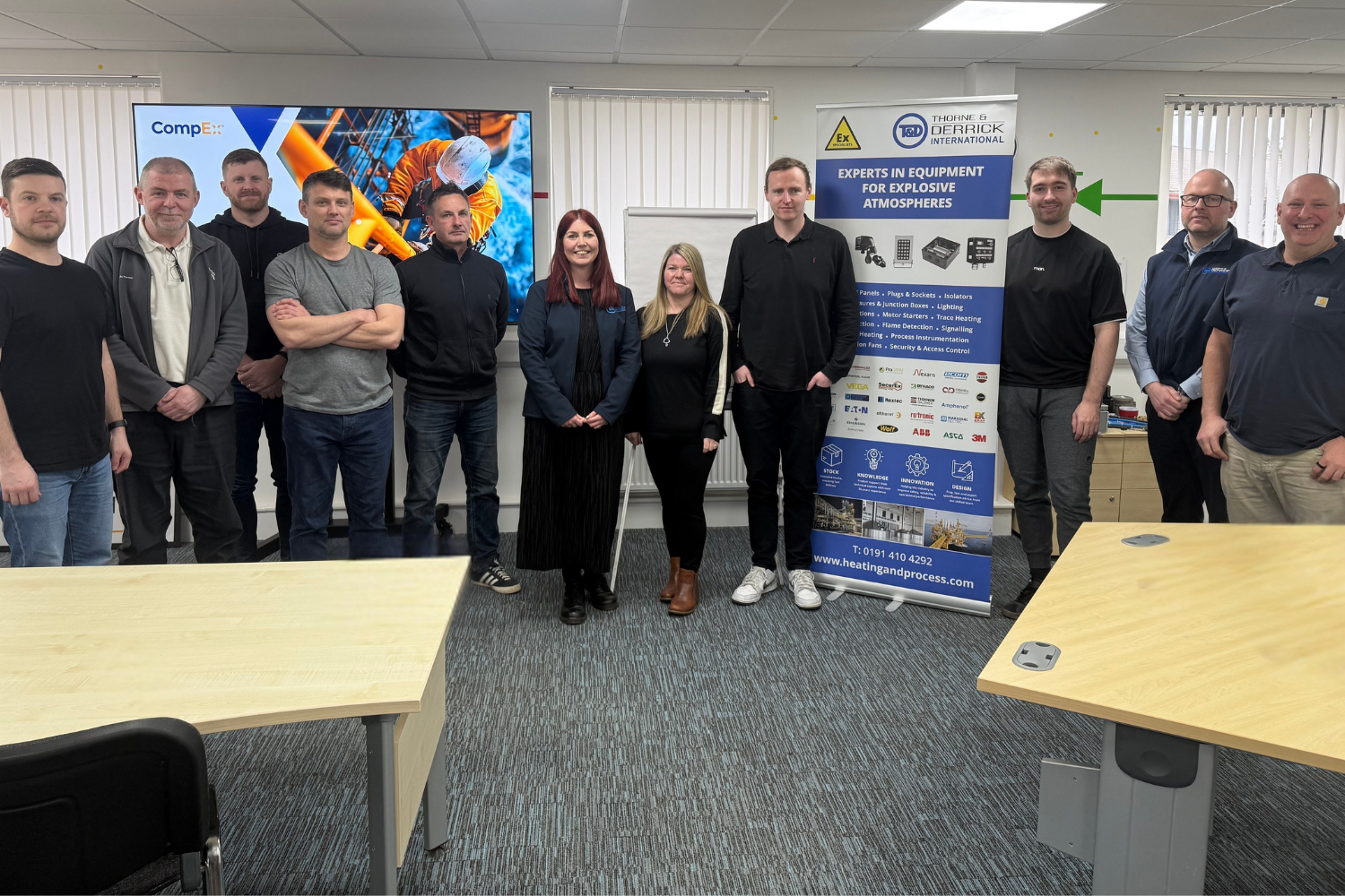
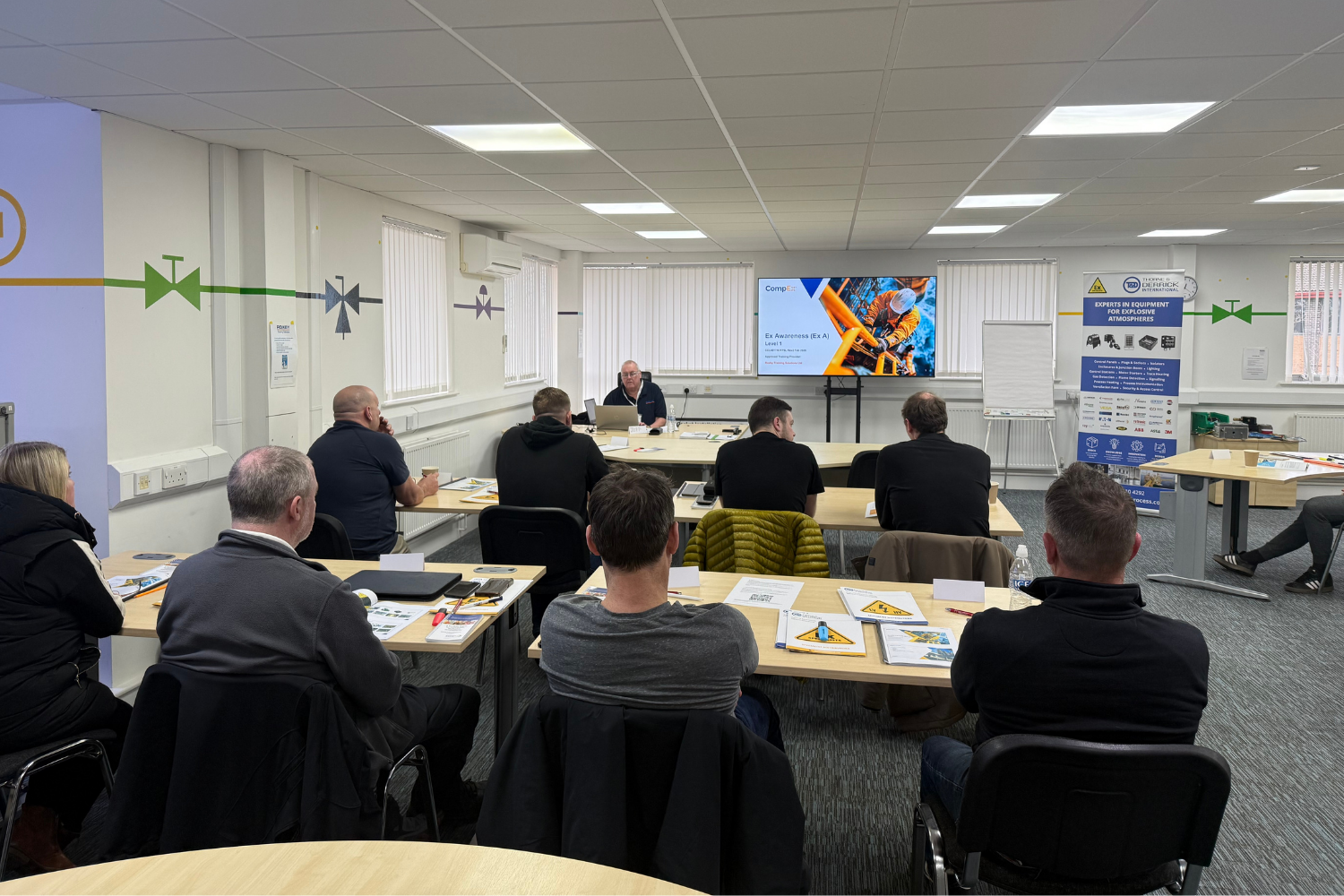
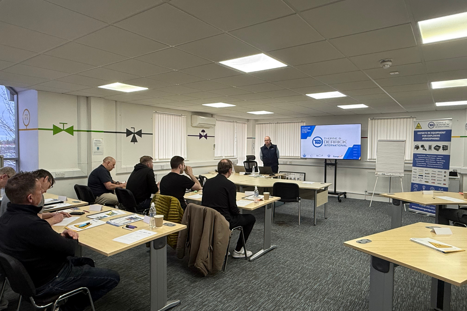
At Thorne & Derrick, we recently delivered a fully funded CompEx Ex Awareness (Ex A) course in partnership with Roxby Training Solutions.
The response to the campaign was immediate. With 200+ registrations, it became clear that there is a strong appetite across industry for improving knowledge — not only within engineering roles, but across everyone involved in hazardous area operations, procurement, and support.
In practical terms, the initiative brought that message to life.
From that response, 10 delegates were selected to attend the course, and we are pleased to say that all 10 successfully passed.
Initiative Summary:
Course: CompEx Ex Awareness (Ex A)
Format: Fully funded by Thorne & Derrick
Delivered by: Roxby Training Solutions
Registrations: 200+
Delegates Selected: 10
Outcome: All 10 delegates successfully passed
What Delegates Told Us
One of the strongest outcomes from the day was the delegate feedback. A consistent theme ran through the comments: a greater understanding of risk, responsibility, and the importance of compliant equipment in hazardous areas.
Some of the clearest takeaways included:
“Opened my eyes to fake and compromised Ex equipment.”
“To understand the risk and how to source / recognise the correct equipment.”
“Everyone can have a basic understanding.”
“The importance of using verified suppliers for Ex certified equipment.”
These responses reflect a simple but important point: awareness changes behaviour – and behaviour ultimately impacts safety.
Several responses also reinforced the importance of recognising compliant equipment and asking better questions at specification and purchasing stage — exactly the kind of thinking that helps reduce risk before equipment ever reaches site.
Crucially, every delegate confirmed that their company would benefit from Terry’s Fake ATEX / non-compliant equipment presentation, reinforcing that the need for awareness extends beyond the individual and across wider teams and organisations.
Terry McDonald’s Message
As part of the day, Terry McDonald delivered a presentation focused on the risks of Fake ATEX / non-compliant equipment – an issue that continues to present real danger across the supply chain.
“I have long been a campaigner against fake ATEX equipment in our industry and equally so on the need to improve knowledge within the hazardous area sector, not just for engineering disciplines but for all those who work in the industry. This course provides a basic understanding and highlights the dangers and consequences when things go wrong. It’s almost 40 years since 167 men never went home. They should never be forgotten, and we should never stop learning and striving to improve knowledge and safety.”
That message resonated strongly with the room and reinforced a core principle behind this initiative: safer outcomes do not begin only with compliant products, but with people who understand the consequences of getting things wrong.
Video Insight
Piper Alpha remains one of the clearest reminders of why proactive learning and safety improvement matter. This short film captures the human legacy behind that lesson.
The film was produced for Step Change by The Art Department and features audio from the BBC Radio 3 drama Piper Alpha – The Human Price of Oil by Stephen Phelps. The artwork was drawn by Sue Jane Taylor, who was offshore in the months before the disaster. She sketched many of the men on Piper Alpha and went on to create the iconic memorial that now stands in Hazlehead Park.
Why This Still Matters Today
Piper Alpha led to major changes in offshore safety, but its wider lesson remains just as relevant today:
Safety should not improve only after disaster
Risk should be addressed before something goes wrong
Teams need to understand the importance of compliant equipment
Awareness must support better procurement, specification, and site decisions
That is why initiatives like this matter. They help move the conversation forward before tragedy forces change and reinforce the importance of awareness at every stage of the supply chain.
Continuing to Do Better
This initiative is one step – but it reflects something bigger.
A responsibility to raise awareness across hazardous area industries, challenge the risks of Fake ATEX / non-compliant equipment, and support better decision-making across the supply chain.
At Thorne & Derrick, we see first-hand how improved awareness, correct specification, and compliant supply can reduce risk and raise standards. But ultimately, safer outcomes do not start with products alone. They start with people who understand the consequences of getting it wrong.
Need Support with Hazardous Area Compliance?
Speak to Thorne & Derrick for support with compliant hazardous area equipment, specification guidance, and future awareness initiatives.
Press Release Date: 02.04.2020 uploaded by Chris Dodds (T&D Sales + Marketing Manager) World’s First Fully Certified ATEX Doors Thorne & Derrick International, the Experts in Equipment for Explosive Atmospheres, today announce the signing of a Commercial Distribution Agreement...
Press Release Date: 04.07.2019 uploaded by Chris Dodds (T&D Sales + Marketing Manager) Category: Stockist Distributor Agreement Announcement Thorne & Derrick International announce that they have signed a Preferred Distributor Agreement with Raytec, the world leading manufacturer of LED...