Article Written By Woodcock & Wilson | 3 of 6 Articles
Woodcock & Wilson are specialist manufacturers of independently certified ATEX fans and IECEx industrial fans for the ventilation of hazardous area locations and potentially explosive atmospheres.
Below is Part 3 in a series of 6 Articles by Woodcock & Wilson discussing fans, the laws, common problems, troubleshooting the main performance issues and getting your fan started again if you encounter any issues.
Fans will only meet the duty point shown on the performance curve under “ideal” installation conditions. Ideal conditions are seldom obtainable in practice consequently there will always be some “SYSTEM EFFECT”.
Factors That Influence Fan System Effect
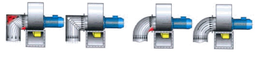
Elbow or bend too close to fan inlet or outlet
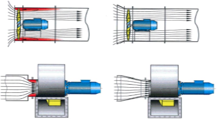
Abrupt duct transition
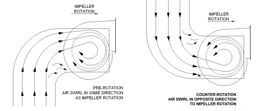
Pre swirl of the incoming air due to duct design. (Swirl in same direction as rotation).
Dampers not fully open
Damper location
Poorly designed fan drives – large drive pulley – solid rather than spoked
Fan inlet or outlet too close to wall or bulkhead
Fan inlet box design
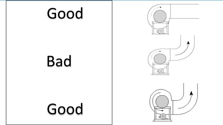
Bend orientations at discharge
Free discharge – abrupt expansion
Weather cowls and hoods
Some Do’s & Don’t’s When For Fan Installations
Fan Discharge Orientation
Fan Inlet Swirl
Experts In Equipment for Explosive Atmospheres with ATEX & IECEx Certification
LEADERS IN ATEX INNOVATION
T&D are your first-choice provider of innovative and competitive solutions to ensure ATEX & IECEx Compliance for Hazardous Area Electrical, HVAC & Process Instrumentation Equipmentto your UK and international projects.
Article Written By Woodcock & Wilson | 2 of 6 Articles
Woodcock & Wilson are specialist manufacturers of independently certified ATEX fans and IECEx industrial fans for the ventilation of hazardous area locations and potentially explosive atmospheres.
Below is Part 2 in a series of 6 Articles by Woodcock & Wilson discussing fans, the laws, common problems, troubleshooting the main performance issues and getting your fan started again if you encounter any issues.
The fans are used to determine theoretical performance data for varying combinations of impeller speed, diameter and air densities.
Here we will only consider the relationship and effect of speed on volume, pressure and power for a constant impeller diameter handling air at a constant density.
When speed is varied on the same size, handling constant density air (e.g. fan used with frequency inverter drive).
Fan Laws Further Explained
Flow Rate varies directly as the speed.
Q2 m³/s = (rpm2/rpm1) x Q1 m³/s
Pressure varies as the square of the speed.
P2 Pa = (rpm2/rpm1)² x P1 Pa
Power varies as the cube of speed.
Power2 kW= (rpm2/rpm1)³ x Power1 kW
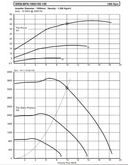
Performance Curve Showing Speed Variation
Maximum speed: 1480 RPM.
Reduced speeds :
• 1110 RPM (75%)
• 740 RPM (50%)
Performance Curve Showing Speed Variation
Here we will only consider the relationship and effect of fan diameter on volume, pressure and power for a constant impeller speed handling air at a constant density:
Flow Rate varies as the cube of the diameter.
Q2 m³/s = (D2/D1)³ x Q1 m³/s
Pressure varies as the square of the diameter.
P2 Pa = (D2/D1)² x P1 Pa
Power varies as the fifth power of the diameter.
Power2 kW= (rpm2/rpm1)5 x Power1 kW
Pressure and Power vary directly proportional to gas density, combining speed, diameter and density we have the following :-
Q2 = Q1 x (n2/n1) x (D2/D1)³ P2 = P1 x (n2/n1)² x (D2/D1)² x (ρ2/ ρ1) W2 = W1 x (n2/n1)³ x (D2/D1)5 x (ρ2/ ρ1)
Where:
Q = flow rate P = pressure (total, static, or dynamic) ρ= gas density n= fan rotational speed D= impeller diameter W= impeller power
Experts In Equipment for Explosive Atmospheres with ATEX & IECEx Certification
LEADERS IN ATEX INNOVATION
T&D are your first-choice provider of innovative and competitive solutions to ensure ATEX & IECEx Compliance for Hazardous Area Electrical, HVAC & Process Instrumentation Equipmentto your UK and international projects.
Article Written By Woodcock & Wilson | 1 of 6 Articles
Woodcock & Wilson are specialist manufacturers of independently certified ATEX fans and IECEx industrial fans for the ventilation of hazardous area locations and potentially explosive atmospheres.
Below is Part 1 in a series of 6 Articles by Woodcock & Wilson discussing fans, the laws, common problems, troubleshooting the main performance issues and getting your fan started again if you encounter any issues.
What is a Fan?
A fan is a machine for transferring energy into moving air. The performance of a fan can be described in terms of Volume Flow, Pressure, Power Absorbed & Efficiency.
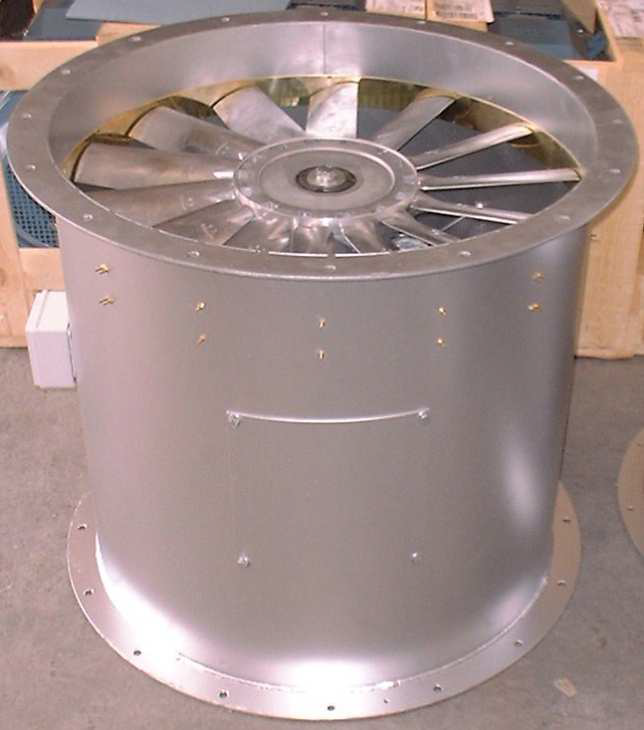
Tubular Case – can be as with a portable man cooler, ducted on either inlet, outlet or both inlet & outlet
Bifurcated Axial – internal tunnel or pod for mounting the motor out of the airstream-used for hot or corrosive gasses
Axial Fans
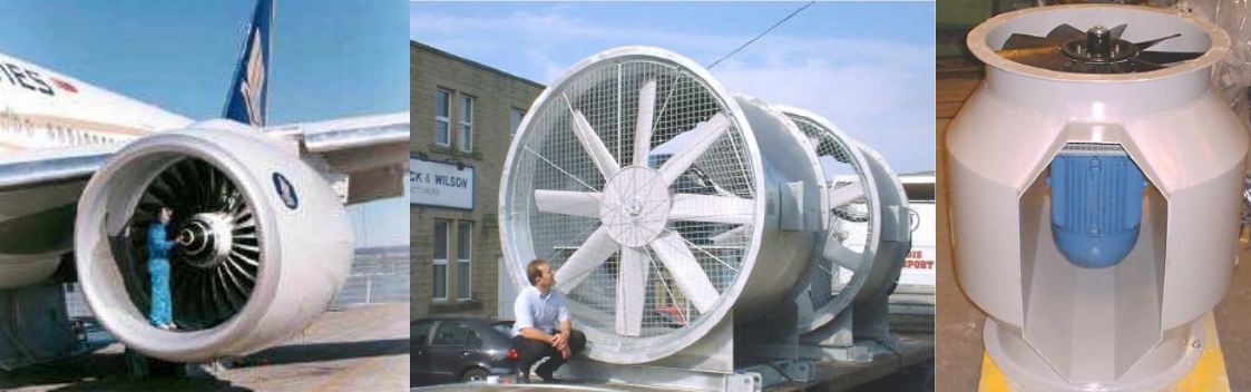
It may come as a surprise that most modern jet engines incorporate a large axial fan. Here the Rolls Royce Trent first stage fan can be seen in all its glory. The fan contributes to around 90% of the thrust generated by the engine and absorbs around 100 MW of power….that’s a big power fan!!
Industrial axial fans come in all shapes and sizes…here are some of them:
Axial Fan Examples
Principles of Operation
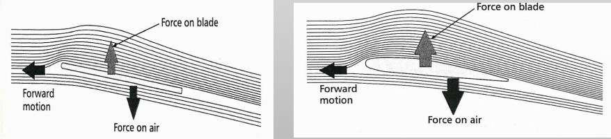
Axial fans work by generating lift within the rotating blades. Newton’s third law states that for every action there exists an equal & opposite reaction. In this case the upward lift force on the blade is balanced by an equal and opposite force making the air flow in the opposite direction.
Principles Of Operation
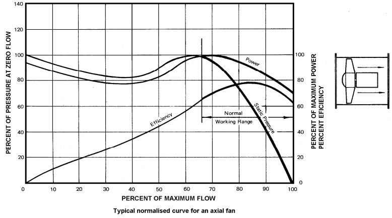
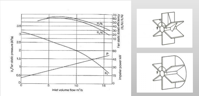
Generally suited for moving large volumes of air at low pressures
Generally low efficiencies- 50%-60%. Larger special designs can achieve static efficiencies in the upper 80’s %
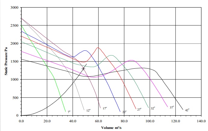
Larger pitches can have a pronounced stall & can be inherently unstable if selected too far to the left of the fan curve. Should be selected well to the left of peak pressure or select a larger fan at a lower pitch angle
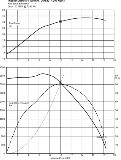
Typical Normalised Curve For An Axial Fan
Static Pressure of Axial Fan
Centrifugal Fans
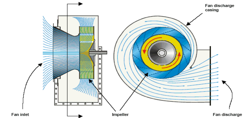
Air enters the fan axially and exits at 90°.
Single inlet-all air is drawn in through one inlet. (SISW)
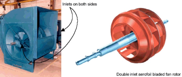
Double inlet-equal amounts of air drawn in through two opposing inlets. (DIDW)
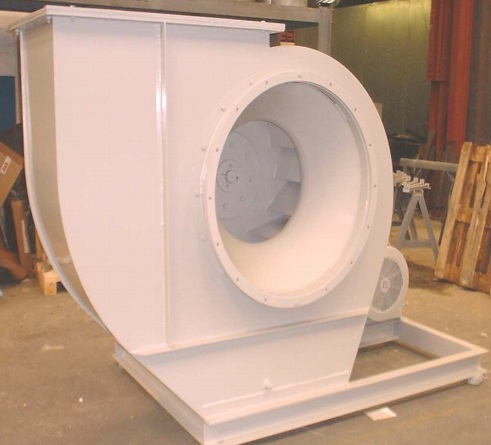
Fan case is an expanding volute shape, which assists static pressure regain and directs the airflow in one direction
Centrifugal Fans
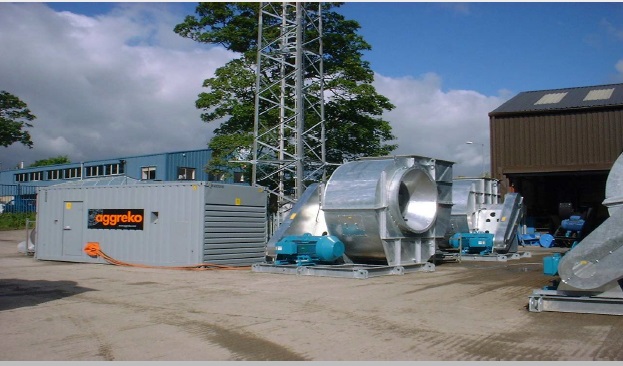
Centrifugal Fans in situ
Double Inlet Double Width (DIDW)
Centrifugal Fan
DIDW Centrifugal
Principles of Fan Operation
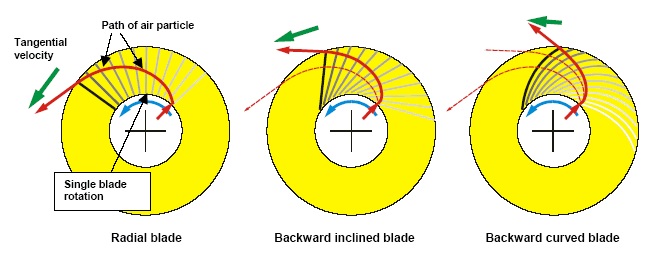
Unlike axial flow fans, which rely on aerodynamic lift from blades, centrifugal fans rely on dragging air round in circles and using centrifugal force to generate air flow.
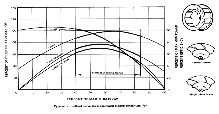
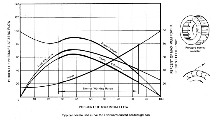
Non overloading power characteristic-power absorbed reaches a peak near the maximum efficiency & then becomes lower towards higher flows
Can exhibit stall characteristics to the left of peak pressure-this could result in instability & vibration. Fan selection point should always be on the steep part of the curve to the right of peak pressure
Can cope with medium erosive gasses in arduous applications
Experts In Equipment for Explosive Atmospheres with ATEX & IECEx Certification
LEADERS IN ATEX INNOVATION
T&D are your first-choice provider of innovative and competitive solutions to ensure ATEX & IECEx Compliance for Hazardous Area Electrical, HVAC & Process Instrumentation Equipmentto your UK and international projects.
T&D are the UK’s largest stockist of Drum, IBC & Tank Heaters & Jackets. Delivering UK & Worldwide.
T&D’s online library of Drum, IBC & Tank Heating applications is now updated to include the following : using IBC jacket to maintain water within a storage facility for washing system equipment.
Visit Silicone Heating Products for details of electric surface heating solutions – flexible silicone heaters can be applied to heat the most complex shapes, geometries, curves and pipes.
Medium Temperature Heating (21-50 degrees Celsius)
High Temperature Heating (50 degrees Celsius+)
Other ✓ Water for cleaning/wash down
IBC Heating Jackets – T&D supply heating and insulating jackets for plastic or steel metal cage IBC’s for bulk liquid storage.
HEATING JACKET VOLTAGE
110 Volt
230 Volt ✓
Low Voltage
HEATING APPLICATION : DRUM, IBC, TANK OR VESSEL
25 Litres
50 Litres
105 Litres
205 Litres
1000 Litres ✓ Schutz
Other
VESSEL MATERIAL
Steel
Stainless Steel
Plastic
Cardboard
Other
HEAT UP TEMPERATURE
0-5 degrees Celsius
5-20 degrees Celsius
20-50 degrees Celsius ✓
50-70 degrees Celsius
70+ degrees Celsius
N/A (Frost Protection)
HEAT UP TIME REQUIREMENT
0-4 Hours
4-12 Hours
12-24 Hours
24-48 Hours ✓
N/A
Contact T&D for specification, support and sales of Electrical Heating Equipment for safe, industrial and hazardous area plant and equipment – we provide process temperature heating and pipework frost protection (Winterisation) products for pipework, valves, IBC’s, drums and tanks. Complete range of heating cables and trace heating cables are available for process temperature maintenance.
T&D – Largest UK Stockist of Heat Tracing Cables. UK & International Delivery.
EXPERTS IN EQUIPMENT FOR EXPLOSIVE ATMOSPHERES
T&D are your first-choice provider of innovative and competitive solutions to ensure ATEX & IECEx Compliance for Hazardous Area Electrical, HVAC & Process Instrumentation Equipmentto your UK and international projects.
T&D are the UK’s largest stockist of Drum, IBC & Tank Heaters & Jackets. Delivering UK & Worldwide.
T&D’s online library of Drum, IBC & Tank Heating applications is now updated to include the following : heating up oil in small pots for use laboratory testing.
Visit Silicone Heating Products for details of electric surface heating solutions – flexible silicone heaters can be applied to heat the most complex shapes, geometries, curves and pipes.
Medium Temperature Heating (21-50 degrees Celsius)
High Temperature Heating (50 degrees Celsius+) ✓
Other
IBC Heating Jackets – T&D supply heating and insulating jackets for plastic or steel metal cage IBC’s for bulk liquid storage.
HEATING JACKET VOLTAGE
110 Volt
230 Volt ✓
Low Voltage
HEATING APPLICATION : DRUM, IBC, TANK OR VESSEL
25 Litres
50 Litres
105 Litres
205 Litres
1000 Litres
Other ✓ Custom size 700 x 1550 to suit 450mm Diameter
VESSEL MATERIAL
Steel ✓
Stainless Steel
Plastic
Cardboard
Other
HEAT UP TEMPERATURE
0-5 degrees Celsius
5-20 degrees Celsius
20-50 degrees Celsius
50-70 degrees Celsius ✓
70+ degrees Celsius
N/A (Frost Protection)
HEAT UP TIME REQUIREMENT
0-4 Hours ✓
4-12 Hours
12-24 Hours
24-48 Hours
N/A
Contact T&D for specification, support and sales of Electrical Heating Equipment for safe, industrial and hazardous area plant and equipment – we provide process temperature heating and pipework frost protection (Winterisation) products for pipework, valves, IBC’s, drums and tanks. Complete range of heating cables and trace heating cables are available for process temperature maintenance.
T&D – Largest UK Stockist of Heat Tracing Cables. UK & International Delivery.
EXPERTS IN EQUIPMENT FOR EXPLOSIVE ATMOSPHERES
T&D are your first-choice provider of innovative and competitive solutions to ensure ATEX & IECEx Compliance for Hazardous Area Electrical, HVAC & Process Instrumentation Equipmentto your UK and international projects.
Press Release Date: 02.04.2020 uploaded by Chris Dodds (T&D Sales + Marketing Manager) World’s First Fully Certified ATEX Doors Thorne & Derrick International, the Experts in Equipment for Explosive Atmospheres, today announce the signing of a Commercial Distribution Agreement...
Press Release Date: 04.07.2019 uploaded by Chris Dodds (T&D Sales + Marketing Manager) Category: Stockist Distributor Agreement Announcement Thorne & Derrick International announce that they have signed a Preferred Distributor Agreement with Raytec, the world leading manufacturer of LED...