A Step-by-Step Electrical Heat Tracing Cable Selection Guide
Quick Navigation
How to Select Heat Trace Cable: Overview
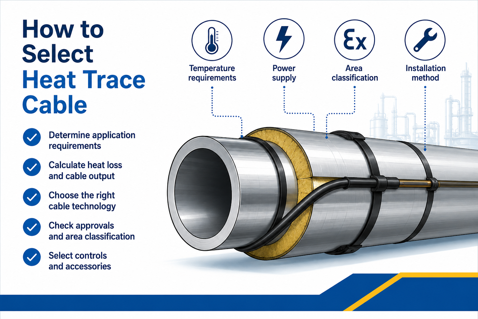
Knowing how to select heat trace cable requires more than choosing a watts-per-metre rating. The cable must compensate for the calculated heat loss while remaining suitable for the maintain temperature, maximum exposure temperature, circuit length, pipe material, environment, controls and area classification.
For readers who need the system fundamentals, see trace heating for frost protection and temperature maintenance. This guide focuses on the specification process rather than providing another general explanation.
The selection outcome should define:
- Heating cable technology and product family
- Required nominal output and performance at temperature
- Number and arrangement of cable runs
- Maximum circuit length and electrical protection
- Power connections, end seals, splices and tees
- Temperature sensors, controllers and limiters
- Safe-area or hazardous-area approvals
- Installation, testing and maintenance requirements
1. Define the Heating Duty
Begin by establishing what the system must achieve.
| Duty |
Primary Objective |
Key Design Question |
| Frost protection |
Keep water or process fluid safely above its freezing point |
What is the lowest design ambient temperature and required protective margin? |
| Process temperature maintenance |
Keep a product pumpable, flowable or within a process range |
What maintain temperature is required for viscosity, crystallisation or production? |
| Hot-water maintenance |
Maintain distribution temperature while limiting heat loss |
What water temperature and circulation strategy must be maintained? |
| Controlled heat-up |
Raise a pipe, vessel or product temperature within a defined period |
What energy is required for the mass, heat capacity and target heat-up time? |
| Winterisation |
Protect multiple exposed plant systems during cold weather |
Which lines and equipment are critical and how are circuits grouped and monitored? |
Do not assume that normal operating temperature is the same as the minimum temperature the trace heating system must maintain.
2. Calculate the Heat Loss
A trace heating heat loss calculation establishes the heating output required to replace the heat escaping through the insulation under the design conditions.
- Required maintain temperature
- Minimum ambient temperature
- Pipe diameter and material
- Insulation type and thickness
- Indoor, outdoor and wind exposure
- Valves, flanges, supports and other heat sinks
- Design allowance and any heat-up requirement
Do Not Select from Pipe Size Alone
Two pipes of the same diameter can require different cable outputs because maintain temperature, ambient conditions, insulation and exposure differ. Cable selection should follow the thermal calculation.
3. Confirm Every Relevant Temperature Limit
The cable and every component must be suitable for both normal operation and credible exposure conditions.
Record these temperatures:
- Required maintain temperature
- Minimum ambient temperature
- Maximum normal process temperature
- Maximum intermittent or exposure temperature
- Steam-cleaning, purging or sterilisation temperature
- Minimum installation temperature
- Maximum permitted pipe or equipment surface temperature
- Required hazardous-area temperature class, where applicable
4. Record the Pipe, Vessel or Equipment Details
Cable performance and installation method depend on the surface being heated.
- Pipe outside diameter, length and material
- Tank or vessel dimensions and shape
- Number and size of valves, flanges and pumps
- Pipe supports, shoes and instruments
- Plastic or temperature-sensitive surfaces
- Removable sections and maintenance access
- Available straight runs and cable-routing restrictions
- Insulation and external cladding specification
Plastic pipework may require output limitations, heat-spreading foil or a specific installation method to prevent local overheating.
5. Choose the Heat Trace Cable Technology
| Cable Technology |
Common Selection Reasons |
Main Design Considerations |
| Self-regulating |
Variable ambient conditions, frost protection, complex fittings and field cut-to-length installation |
Output at maintain temperature, start-up current, maximum circuit length and temperature limits |
| Constant wattage / parallel resistance |
Defined output, controlled process duties and specialist cable constructions |
Control method, zone spacing, cable contact, exposure temperature and maximum circuit length |
| Series resistance |
Long circuits and engineered industrial duties |
Fixed designed length, voltage, conductor resistance, output and termination arrangement |
| Mineral-insulated |
High temperatures, high output, severe environments and engineered long circuits |
Sheath alloy, resistance design, sheath temperature, cold leads, joints and specialist installation |
Use the detailed self-regulating vs constant wattage trace heating comparison and the guide explaining when mineral-insulated heat trace cable is required to narrow the technology choice.
6. Confirm Cable Output at the Design Temperature
Nominal cable output is often quoted at a reference temperature. The available output at the actual maintain temperature can differ.
- Use manufacturer power-output curves or approved design software
- Apply the correct pipe-material and installation correction factors
- Check whether one or multiple cable runs are required
- Confirm cable spacing around fittings and local heat sinks
- Verify maximum sheath or surface temperature
- Avoid unnecessary oversizing that increases electrical load and control cycling
7. Check Voltage, Circuit Length and Electrical Protection
Cable selection must be coordinated with the available electrical supply and the proposed circuit architecture.
| Electrical Input |
Why It Matters |
| Supply voltage |
Only cable variants designed for the available voltage should be selected |
| Maximum circuit length |
Affected by cable type, output, voltage, breaker size and minimum start-up temperature |
| Start-up current |
Self-regulating cable can draw increased current when cold |
| Operating current |
Determines connected load, switching and distribution requirements |
| Circuit protection |
Must match manufacturer data, wiring rules and the site design |
| Earth-fault protection |
Required arrangement depends on the electrical and system standard |
| Power-feed locations |
Can reduce circuit length or determine single- and dual-end supply arrangements |
8. Assess Environmental and Hazardous-Area Conditions
The outer jacket, braid, sheath, connection kits and enclosures must be suitable for the installation environment.
- Indoor, outdoor, offshore or buried location
- Moisture, UV and weather exposure
- Chemical, oil, solvent or corrosive exposure
- Mechanical impact and abrasion
- Food, hygiene or washdown requirements
- Safe-area or hazardous-area classification
- Gas group, dust group and temperature class
- Ambient-temperature range
For explosive atmospheres, use a complete ATEX trace heating system selected for the area classification and certification conditions.
9. Select Controls, Sensors and Connection Components
The heating cable is only one part of the circuit. A complete design may include:
System components:
- Power connection and junction box
- End seal
- Splice and tee connection kits
- Temperature sensor
- Ambient- or pipe-sensing thermostat
- Electronic controller and alarm system
- Independent temperature limiter
- Distribution panel and protective devices
- Fixing tape, support brackets and warning labels
- Thermal insulation and weatherproof cladding
Select controls for the duty rather than treating them as optional accessories. Hazardous-area options include digital heat trace thermostats and temperature limiters.
10. Verify the Complete Electrical Heat Tracing System
Before ordering, verify that the selected products form a compatible and documented system.
- Confirm the heat-loss and cable-output calculation
- Check cable temperature, voltage and circuit-length limits
- Confirm the number and position of power feeds
- Select manufacturer-approved power connections and terminations
- Verify controller, sensor and limiter ranges
- Confirm the enclosure and component environmental ratings
- Check hazardous-area certificates and conditions of use
- Prepare cable schedules, circuit drawings and a bill of materials
- Define installation and commissioning tests
- Obtain technical approval for critical or complex systems
Quick Heat Trace Cable Selection Table
| Application Requirement |
Technology to Investigate First |
Further Check |
| Basic water-pipe frost protection |
Self-regulating |
Pipe material, minimum ambient, insulation and circuit length |
| Variable ambient conditions |
Self-regulating |
Output at maintain temperature and start-up current |
| Defined process output |
Constant wattage or resistance |
Control, exposure temperature and cable spacing |
| Long industrial pipeline |
Series resistance, MI or suitable parallel cable |
Voltage, power feeds, circuit length and control architecture |
| Very high temperature |
MI or specialist resistance cable |
Sheath material, joints, cold leads and temperature limiting |
| Hazardous area |
Certified cable technology suited to the duty |
Complete system certification, temperature class and accessories |
| Plastic pipe |
Approved lower-output cable and installation method |
Maximum pipe temperature and heat-spreading requirements |
Heat Trace Cable Design Information Checklist
Application information to provide:
- Purpose of the system
- Fluid or product
- Required maintain temperature
- Minimum ambient temperature
- Maximum process and exposure temperatures
- Pipe or equipment material and dimensions
- Pipe length and quantity of fittings
- Insulation material and thickness
- Available voltage
- Indoor, outdoor or hazardous-area location
- Required heat-up time
- Preferred control, monitoring and alarm functions
Once these details are confirmed, explore the complete heat trace cable range or request an engineered specification.
Common Heat Trace Cable Selection Errors
- Choosing cable from pipe diameter or nominal wattage alone
- Using average ambient temperature instead of the minimum design temperature
- Ignoring maximum exposure or cleaning temperature
- Assuming self-regulating cable never requires controls
- Cutting constant wattage or series cable outside its permitted method
- Failing to include valves, flanges and supports
- Ignoring start-up current and maximum circuit length
- Specifying a hazardous-area cable without compatible certified components
- Treating thermal insulation as outside the system design
- Selecting products before the heat loss and operating duty are known
Heat Trace Cable Selection FAQs
What Is the First Step When Selecting Heat Trace Cable?
Define the duty and calculate the heat loss using the required maintain temperature, minimum ambient temperature, pipe dimensions and insulation specification.
Can Cable Be Selected Using Watts Per Metre Alone?
No. The output must be checked at the design temperature and coordinated with temperature ratings, voltage, circuit length, controls, pipe material and environmental approvals.
Which Cable Is Best for Frost Protection?
Self-regulating cable is frequently considered, but the final selection depends on heat loss, pipe material, insulation, voltage, circuit length and location.
Which Cable Is Used for High-Temperature Applications?
Mineral-insulated or specialist resistance cables may be required. Selection depends on maintain and exposure temperatures, output, circuit length, sheath material and control requirements.
Does Hazardous-Area Cable Need Special Accessories?
Yes. Power connections, end seals, junction boxes, controls, glands and other components must be suitable for the cable, area classification and certification conditions.
Should Heat Trace Cable Be Oversized for Safety?
A justified design allowance may be applied, but excessive output can increase load, energy use and surface temperature. Accurate data and appropriate control are safer than arbitrary oversizing.
Need Help Selecting Heat Trace Cable?
Thorne & Derrick provides technical support from heat-loss calculation through cable, control and component specification.
- Frost-protection cable selection
- Process temperature-maintenance design
- Self-regulating, constant wattage and MI technology
- Circuit length and electrical load review
- Controllers, sensors and limiters
- ATEX and hazardous-area system specification
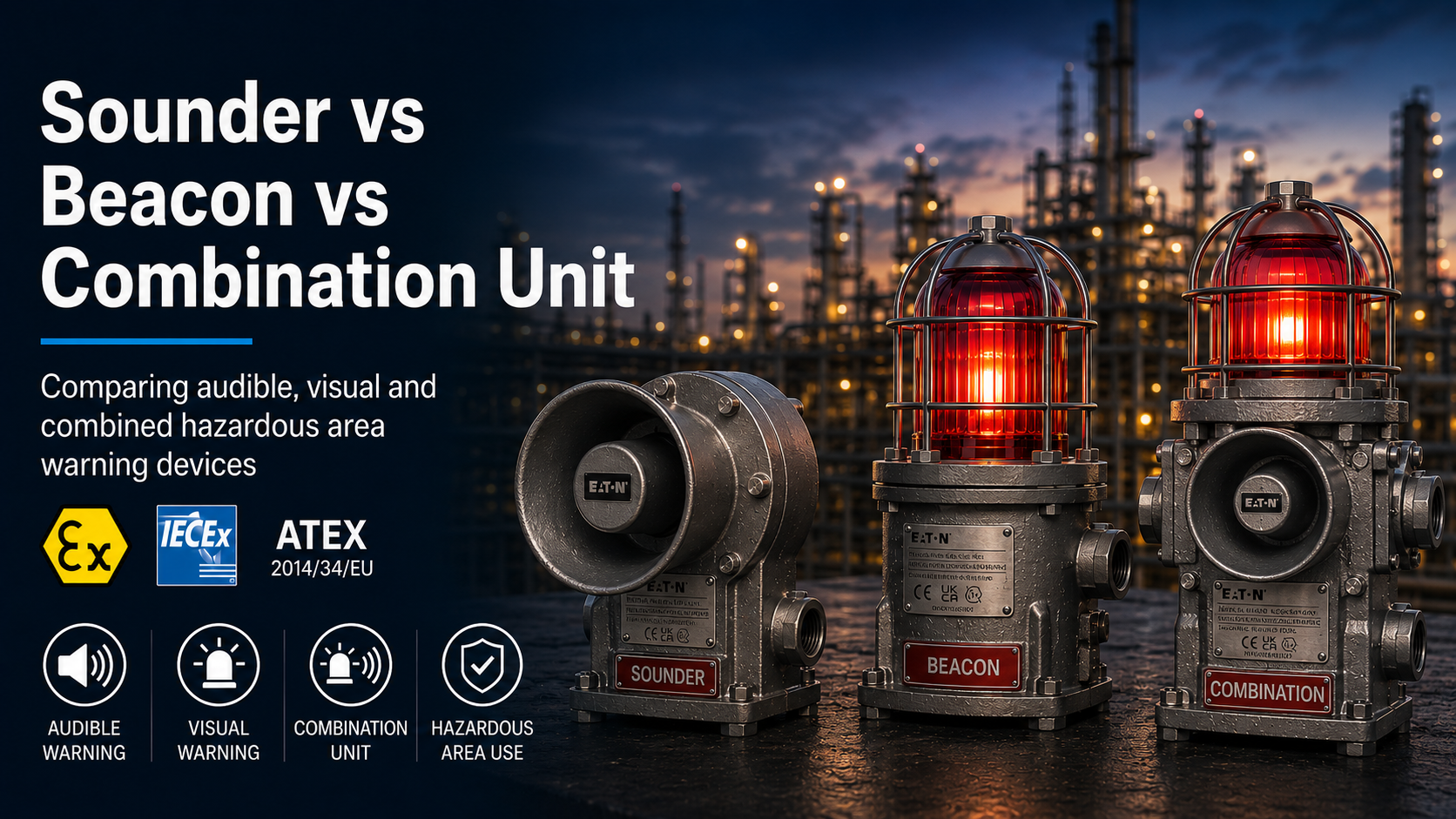
Sounders, beacons and combination units communicate alarms and equipment conditions in different ways. A sounder produces an audible warning, a beacon provides a visual signal, and a combination unit brings both warning methods together within one assembly.
The correct choice depends on who must receive the warning, the surrounding noise and lighting conditions, the required alarm response and the hazardous area classification.
Thorne & Derrick supplies a comprehensive range of hazardous area sounders, beacons and combination units for audible, visual and combined signalling in potentially explosive atmospheres.
Quick answer: select a sounder where personnel must hear the alarm, a beacon where they must see it, and a combination unit where audible and visual warning should be provided from the same signalling point. The final choice must follow the site alarm philosophy and hazardous area specification.
Sounder vs Beacon vs Combination Unit: Quick Comparison
| Device |
Warning Method |
Main Strength |
Potential Limitation |
Key Selection Data |
| Sounder |
Audible alarm tone, horn or bell |
Can alert personnel who are not looking towards the device |
Recognition can be affected by high noise, distance or hearing protection |
Sound output, tone, frequency, coverage, voltage and current |
| Beacon |
Visual light signal |
Provides a visible warning or persistent status indication |
Requires a suitable line of sight and sufficient contrast |
Light source, signal mode, colour, visibility, voltage and current |
| Combination Unit |
Audible and visual signals |
Provides two warning methods from one signalling location |
Electrical demand, control logic and certification can be more complex |
Sounder data, beacon data, input arrangement, mounting and total load |
Important: a combination unit is not automatically required for every alarm. The selected warning method should be based on the risk assessment, alarm philosophy, personnel needs and environmental conditions.
What Is a Hazardous Area Sounder?
A sounder is an audible signalling device that produces a tone, horn, siren or bell output when activated.
The signal can warn personnel of an emergency, communicate an evacuation instruction, indicate an equipment condition or distinguish between different alarm states.
Typical Sounder Applications
- Fire and gas detection alarms
- Evacuation or shelter-in-place warnings
- Process trip or shutdown alarms
- Machinery start-up warnings
- General emergency notification
- Site-specific coded alarm tones
Sound Output
Sounders are commonly specified using a sound-pressure level stated in dB(A) at a defined distance. The test distance and tone should be checked because output can vary between tone settings.
A higher stated sound output does not automatically guarantee that the alarm will be understood throughout the area. Machinery noise, walls, pipework, distance, hearing protection and the frequency content of the alarm can all affect recognition.
Tone Selection
Many electronic sounders provide several selectable tones. The chosen tone should remain recognisable against the background noise and distinct from other plant alarms.
Explore ATEX sounders for hazardous area audible warning.
What Is a Hazardous Area Beacon?
A beacon is a visual signalling device that uses light to communicate an alarm, warning, process event or equipment status.
Depending on the product, the visual output may be steady, blinking, flashing, strobe or rotating. LED, xenon, filament and fluorescent technologies can be available.
Typical Beacon Applications
- Visible fire or gas alarm indication
- Process fault or trip indication
- Machine, valve or plant status
- Emergency warning in high-noise areas
- Persistent visual status indication
- Colour-coded site alarm conditions
Visibility
Beacon visibility is influenced by the optical output, signal pattern, lens colour, ambient lighting, mounting position, viewing distance and surrounding obstructions.
A beacon may be particularly useful where personnel wear hearing protection, the background noise is high or a persistent visual status must remain available.
Explore ATEX beacons for hazardous area visual signalling.
What Is a Sounder-Beacon Combination Unit?
A combination unit provides audible and visual warning from one assembled signalling point.
The sounder and beacon may be incorporated within one enclosure or assembled together on a common mounting plate. Backplate-mounted units can combine separate certified sounder and beacon products into one pre-arranged assembly.
Combined vs Independent Operation
Some combination units are pre-wired so that one input activates the sounder and beacon simultaneously. Other configurations can provide separate inputs or multi-stage control, allowing the audible and visual signals to operate independently.
The required input arrangement must therefore be confirmed before ordering. It should not be assumed from the product description alone.
Benefits of a Combination Unit
- Audible and visual warning from the same location
- Can reduce the number of separate mounting positions
- Can simplify installation where a pre-wired assembly is specified
- Provides complementary warning methods
- Can support personnel affected by either noise or visibility limitations
- Can be configured around different sounder and beacon technologies
Combination-Unit Considerations
- Total current consumption
- Single or independent activation inputs
- Required sound output and visual output
- Overall dimensions and mounting loads
- Cable-entry and termination arrangements
- Certification of the complete assembly
- Maintenance access to both signalling devices
Explore hazardous area sounder-beacon combination units.
When Should You Select a Sounder, Beacon or Combination Unit?
Consider a Sounder When:
- Personnel may not be looking towards the alarm point
- An evacuation tone or audible instruction is required
- The warning must extend beyond direct line of sight
- The alarm philosophy uses distinctive audible tones
- Background noise conditions have been properly assessed
Consider a Beacon When:
- A visual alarm or status indication is required
- The surrounding area is particularly noisy
- Personnel regularly wear hearing protection
- A persistent equipment or process state must remain visible
- Line of sight and visual contrast can be maintained
Consider a Combination Unit When:
- Both audible and visual notification are required
- Different personnel may recognise different warning methods
- One assembled signalling point is preferred
- Noise and visibility conditions vary across the area
- The control system supports the required input and electrical load
Audibility and Background Noise
Audible warning performance depends on more than the sounder’s maximum stated dB(A) output.
Consider:
- Normal and maximum background-noise levels
- Distance between the sounder and personnel
- Walls, enclosures, vessels and process equipment
- Frequency content of the background noise
- Hearing protection worn by personnel
- Other alarm tones operating in the area
- Required alarm coverage and response time
Where the audible alarm could be masked or misunderstood, a beacon or combination unit may provide an additional visual warning method.
Visibility and Line of Sight
A beacon must be positioned so that the intended personnel can see and interpret its signal from the required working locations.
Consider:
- Viewing distance
- Mounting height and orientation
- Direct sunlight and ambient lighting
- Structures or equipment blocking the signal
- Required horizontal and vertical field of view
- Lens or LED colour
- Steady, flashing, strobe or rotating operation
- Other visible alarms in the same area
Read Steady vs Flashing vs Rotating ATEX Beacons for a comparison of visual signal modes.
Control and Wiring Requirements
The alarm-system design must support the selected product’s voltage, current consumption, switching and monitoring requirements.
| Control Requirement |
Sounder |
Beacon |
Combination Unit |
| Electrical load |
Sounder current at selected voltage and tone |
Beacon current for selected colour and signal mode |
Combined or independently switched load |
| Inputs |
Single-stage or multi-stage tone activation |
Fixed, selectable or remotely controlled mode |
Common input or independent sounder and beacon inputs |
| Monitoring |
Confirm system supervision and end-of-line requirements |
Confirm monitoring compatibility and polarity |
Confirm supervision for both circuits or the combined assembly |
Do not assume simultaneous operation: some combination units use one common input, while others support independent or multi-stage activation. Confirm the wiring arrangement from the current product documentation.
Hazardous Area Certification
Sounder, beacon or combination-unit selection must begin with the complete hazardous area specification.
Check:
- Zone 1, Zone 2, Zone 21 or Zone 22 classification
- Gas, vapour, mist or combustible-dust atmosphere
- Gas or dust group
- Equipment category and equipment protection level
- Protection concept
- Temperature class or maximum surface temperature
- Permitted ambient-temperature range
- Required ATEX, UKEX, IECEx or other regional approval
Read the guide to ATEX and IECEx certification of hazardous area equipment.
See also hazardous area zones and explosive atmosphere classification.
Environmental and Installation Conditions
Hazardous area certification does not automatically establish suitability for every outdoor, offshore, marine or corrosive location.
Review:
- Ingress-protection rating
- Enclosure material and corrosion resistance
- Salt spray and marine exposure
- Chemical or hydrocarbon exposure
- UV and weather conditions
- Vibration and mechanical impact
- Minimum and maximum ambient temperature
- Mounting arrangement and structural support
Sounder, Beacon or Combination Unit Selection Checklist
| Question |
Selection Consideration |
| Who must receive the warning? |
Personnel location, duties, hearing protection and line of sight |
| What response is required? |
Evacuate, stop, investigate, acknowledge or continue normal operation |
| Is the area noisy? |
Check whether an audible signal will remain recognisable |
| Is the beacon visible? |
Assess mounting, viewing distance, lighting and obstructions |
| Are both signals required? |
Determine whether separate or combined devices are more suitable |
| How will the unit be controlled? |
Single input, independent inputs, multi-stage operation and monitoring |
| What is the hazardous area? |
Zone, atmosphere, group, temperature and complete certification |
| What environment will it face? |
Outdoor, offshore, chemical, dust, corrosion, vibration and temperature |
Information Required When Specifying the Equipment
Audible, visual or combined warning
Hazardous area zone
Gas or combustible-dust group
Temperature class and ambient range
Required sound output and tones
Beacon light source and signal mode
Lens or LED colour
Operating voltage
Single or independent activation
Background noise and viewing conditions
Mounting and cable entries
Required regional approvals
Related Hazardous Area Signalling Guides
Common Selection Mistakes
Selecting a sounder using only its maximum stated dB(A) output
Assuming a beacon will remain visible from every working position
Using a combination unit when separate warning locations would provide better coverage
Assuming every combination unit uses one common activation input
Ignoring the total current required by the sounder and beacon
Choosing alarm colour or tone without checking the site alarm philosophy
Selecting equipment before confirming the complete hazardous area marking
Sounder, Beacon and Combination Unit FAQs
Is a beacon a replacement for a sounder?
Not automatically. A beacon provides a visual signal while a sounder provides an audible signal. The required alarm method should be determined by the risk assessment and alarm philosophy.
Is a combination unit always safer?
Not in every application. It provides two notification methods, but coverage, positioning, control, electrical load and the required personnel response must still be assessed.
Can the sounder and beacon operate independently?
Some combination units support independent or multi-stage control, while others use one common input. The required arrangement must be confirmed before ordering.
Is the loudest sounder always the best choice?
No. The tone must be audible and recognisable in the intended area without creating unsuitable sound levels. Background noise, distance and frequency are all relevant.
Should high-noise areas always use a beacon?
A visual signal can support alarm recognition in high noise, but its visibility and line of sight must also be assessed. A combination of warning methods may be appropriate.
Does the warning method determine the hazardous area zone?
No. Zone suitability is determined by the complete equipment certification and marking, not by whether the product is audible, visual or combined.
Need Help Selecting an Audible or Visual Alarm?
Send Thorne & Derrick the hazardous area classification, required warning method, sound and visibility conditions, voltage and installation environment for product selection support.
CONTACT THORNE & DERRICK
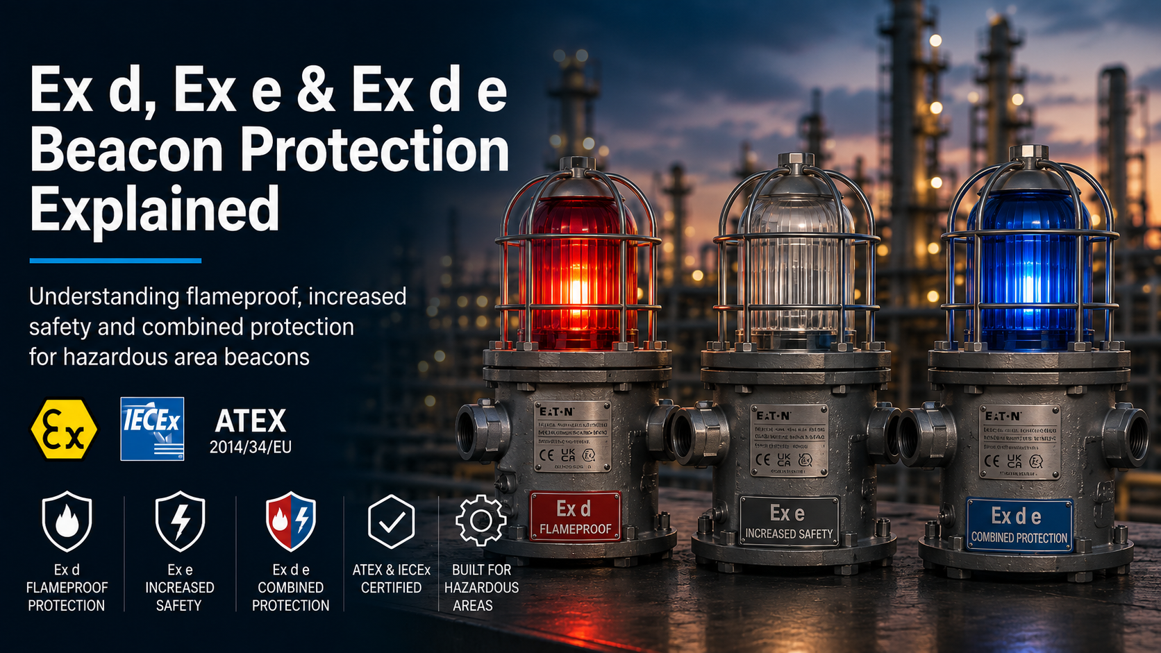
Ex d, Ex e and combined Ex d e markings describe different methods of protecting electrical equipment intended for use in potentially explosive gas atmospheres.
An Ex d beacon uses a flameproof enclosure designed to contain an internal ignition and prevent flame propagation into the surrounding atmosphere. Ex e increased safety uses additional construction measures intended to avoid arcs, sparks and excessive temperatures under the certified operating conditions.
A product marked Ex d e or Ex db eb combines these protection concepts in different parts of the equipment. For example, the optical and electronic components may be housed within a flameproof chamber while the field-wiring terminal compartment uses increased-safety protection.
Thorne & Derrick supplies a comprehensive range of hazardous area visual signalling devices with flameproof, increased-safety and combined protection arrangements.
For a general introduction to visual signalling in potentially explosive atmospheres, read What Is an ATEX Beacon?
Key distinction: Ex d is designed to contain an internal explosion. Ex e is designed to avoid ignition-capable faults through increased constructional safety. A combined Ex d e product applies the appropriate concept to different parts of the equipment.
Ex d vs Ex e vs Ex d e: Quick Comparison
| Protection |
Principle |
Typical Beacon Application |
Important Installation Consideration |
| Ex d / Ex db |
Contains an internal explosion and controls flame propagation through designed flamepaths |
Optical chamber, lamp housing or electronics enclosure |
Flamepaths, threads, fasteners and certified cable entries must remain compliant |
| Ex e / Ex eb |
Uses additional measures to avoid arcs, sparks and excessive temperatures |
Terminal compartment and field-wiring connections |
Terminal capacity, conductor preparation, clearances and connection security are critical |
| Ex d e / Ex db eb |
Applies flameproof and increased-safety concepts to different equipment sections |
Flameproof signalling chamber with a separate increased-safety terminal compartment |
Both protection concepts and their associated installation requirements must be maintained |
Do not interpret the marking in isolation: Ex d, Ex e or Ex d e does not by itself confirm the permitted zone, gas group, temperature class, ambient range or dust suitability. The complete equipment marking and certificate must be checked.
How Does Ex d Flameproof Beacon Protection Work?
An Ex d flameproof enclosure is designed on the basis that an explosive gas atmosphere may enter the enclosure and could be ignited by an internal component.
The enclosure is constructed to withstand the pressure created by an internal explosion. Joints and openings are engineered as flamepaths that cool escaping gases sufficiently to prevent the explosion from propagating into the external atmosphere under the certified conditions.
Ex d does not mean that an explosion can never occur inside the enclosure. Its protection principle is based on containment and controlled flame transmission.
Typical Flameproof Beacon Components
- Lamp, LED or xenon light chamber
- Electronic power-supply components
- Xenon energy-storage and flash circuitry
- Internal switching or operating-mode electronics
- Glass dome and enclosure joint
Flamepaths
Flamepaths can be formed by threaded joints, cylindrical joints, flanged joints or other certified enclosure interfaces.
Their dimensions, finish and condition form part of the certified design. Flamepaths must not be drilled, filed, painted, damaged or modified outside the manufacturer’s permitted procedures.
Ex d Cable Entries
Where the cable enters directly into a flameproof enclosure, the gland, adaptor or stopping plug must be appropriate for the certified entry arrangement, cable type and installation.
An unsuitable cable gland or unapproved modification can compromise the complete protection concept even when the beacon itself carries the correct marking.
What Does “Flameproof” Not Mean?
Flameproof equipment is sometimes described using the general term “explosion proof”. This can lead to misunderstandings about what the construction provides.
It does not mean that an internal explosion is impossible.
It does not mean the enclosure is suitable for every gas group.
It does not establish the temperature class or ambient range.
It does not automatically establish combustible-dust suitability.
It does not permit the enclosure, flamepaths or entries to be modified.
How Does Ex e Increased-Safety Protection Work?
Ex e increased safety uses additional construction measures intended to prevent ignition-capable arcs, sparks and excessive temperatures under the certified operating conditions.
Unlike Ex d, an increased-safety enclosure is not based on containing an internal explosion. Equipment and components are selected so that an ignition source is not expected to develop within the protected section during normal service.
Typical Increased-Safety Measures
- Secure and suitably rated terminals
- Defined creepage and clearance distances
- Enhanced electrical insulation
- Protection against loose conductors and connections
- Control of component and conductor temperatures
- Mechanical protection of field-wiring connections
Increased-Safety Terminal Compartments
On a combined beacon, Ex e is frequently applied to the terminal compartment. This allows the incoming supply cable to be connected without opening the separate flameproof electronics or optical chamber.
The terminals, conductor sizes, stripping lengths and cable-entry equipment must still follow the manufacturer’s instructions and certificate conditions.
Important: Ex e does not make loose strands, incorrect conductor sizes or poorly tightened terminals acceptable. Correct workmanship forms an essential part of maintaining increased-safety protection.
What Does Combined Ex d e Protection Mean?
Combined Ex d e protection means that different sections of the same beacon use different protection concepts.
A typical arrangement includes:
Flameproof Signalling Chamber
The LEDs, lamp, xenon tube, power electronics or energy-storage components are contained within an Ex d or Ex db enclosure.
Increased-Safety Terminal Compartment
The incoming cable and supply conductors terminate within a separate Ex e or Ex eb compartment using increased-safety terminals and entry equipment.
The marking does not mean that every component is simultaneously protected by both concepts. It identifies a certified assembly incorporating more than one method of protection.
Why Combine Ex d and Ex e?
- The ignition-capable electronics can remain inside a flameproof chamber
- Field wiring can be completed in a separate terminal section
- The main flameproof chamber does not normally need to be opened for routine termination
- Different equipment sections can use the protection concept most appropriate to their function
Ex d vs Ex db and Ex e vs Ex eb
Product literature and certificates can use different marking formats depending on the applicable standard edition and approval.
Older or simplified documentation may show:
- Ex d — flameproof enclosure
- Ex e — increased safety
- Ex d e — combined flameproof and increased-safety protection
More detailed markings can include an additional protection-level suffix:
- Ex db — flameproof protection with level “b”
- Ex eb — increased-safety protection with level “b”
- Ex db eb — combined protection using both level “b” concepts
Always use the exact marking shown on the product certificate and equipment label. Do not rewrite or assume a marking based only on a catalogue heading.
How to Read an Ex d e Beacon Marking
The protection concept forms only one part of the complete hazardous area marking.
Ex db eb IIC T6 Gb
Illustrative marking format only. Refer to the actual product certificate and label.
| Marking |
General Meaning |
| Ex |
Equipment uses a recognised explosion-protection concept |
| db |
Flameproof enclosure protection, level “b” |
| eb |
Increased-safety protection, level “b” |
| IIC |
Gas group shown in this illustrative example |
| T6 |
Gas temperature class shown in this illustrative example |
| Gb |
Equipment protection level for a gas atmosphere |
The complete marking may also include the equipment group, category, certificate number, permitted ambient range, ingress protection and special conditions of use.
Read the wider guide to ATEX and IECEx certification of hazardous area equipment.
Does Ex d e Marking Cover Combustible Dust?
Ex d and Ex e are protection concepts associated with explosive gas atmospheres. They do not, by themselves, confirm suitability for combustible dust.
A beacon certified for Zones 21 and 22 will normally carry a separate dust marking. This may include protection by enclosure such as Ex tb, together with a dust group, maximum surface temperature and equipment protection level.
| Atmosphere |
Example Protection Concepts |
Zones Commonly Associated |
| Gas, vapour or mist |
Ex d, Ex e, Ex d e and other gas protection concepts |
Zones 0, 1 and 2, subject to the complete marking |
| Combustible dust |
Ex t or Ex tb protection by enclosure and other applicable concepts |
Zones 20, 21 and 22, subject to the complete marking |
See the guide to hazardous area zones and explosive atmosphere classification for further information about gas and dust zones.
Examples of Ex d and Combined Ex d e Beacons
These product families demonstrate how different protection arrangements can be applied to visual signalling equipment. Always confirm the current certificate and exact ordered configuration.
MEDC FB11 & FL11
The FB11 filament and FL11 fluorescent steady-beacon range uses flameproof construction. Current marking and temperature classification depend on the selected certified variant.
View MEDC FB11 & FL11 steady beacons
Installation Requirements for Ex d and Ex e Beacons
Installation must follow the manufacturer’s instructions, certificate conditions, applicable standards and site procedures.
Ex d Installation Checks
- Correct flameproof cable gland or stopping element
- Correct thread type and engagement
- Flamepaths clean, undamaged and unmodified
- All specified enclosure fasteners installed
- Correct tightening torque where stated
- No unauthorised drilling or machining
- Enclosure not opened while unsafe to do so
Ex e Installation Checks
- Correct increased-safety cable gland and blanking elements
- Conductor size within the terminal rating
- Correct conductor stripping length
- No loose or exposed conductor strands
- Terminals tightened correctly
- Creepage and clearance distances maintained
- Unused entries correctly sealed
Installation, inspection and maintenance should be completed by suitably competent personnel familiar with hazardous area equipment and the relevant protection concepts.
Inspection and Maintenance Differences
| Inspection Area |
Ex d Focus |
Ex e Focus |
| Enclosure |
Damage, corrosion, cracks and pressure-containing integrity |
Damage, ingress, corrosion and environmental protection |
| Joints |
Flamepath condition, threads, covers and fasteners |
Gaskets, covers and protection of terminal clearances |
| Connections |
Certified entry system and internal connection integrity |
Terminal security, conductor condition and insulation |
| Modifications |
Check for unauthorised machining or flamepath alteration |
Check for unapproved terminals, links or wiring changes |
Should You Select Ex d, Ex e or Ex d e?
The protection concept should not be selected independently from the certified beacon design. The manufacturer determines the equipment construction and obtains approval for the complete product.
Product selection should instead confirm:
- Hazardous area zone
- Gas or combustible-dust atmosphere
- Gas or dust group
- Equipment category and protection level
- Temperature class or maximum surface temperature
- Permitted ambient-temperature range
- Required signal technology and operating mode
- Operating voltage and current consumption
- Cable-entry and termination requirements
- Required regional approvals
Read How to Select an ATEX Beacon for the complete product-selection process.
Related Hazardous Area Beacon Guides
Common Ex d and Ex e Beacon Mistakes
Assuming Ex d means an internal ignition can never occur
Assuming Ex e is designed to contain an internal explosion
Treating combined Ex d e as though every component uses both protection concepts
Selecting a beacon from its protection concept without checking its gas group and temperature class
Assuming gas certification automatically covers combustible dust
Installing an unsuitable gland, adaptor or stopping plug
Damaging flamepaths or modifying a certified enclosure
Leaving loose conductor strands or incorrect connections in an Ex e terminal compartment
Ex d, Ex e and Ex d e Beacon FAQs
Is Ex d the same as explosion proof?
Ex d is the IEC flameproof protection concept. “Explosion proof” is often used as a general term, but the exact approval system, marking and technical requirements should always be confirmed.
Can an explosion occur inside an Ex d beacon?
The protection principle assumes an internal ignition may occur. The enclosure is designed to withstand it and prevent flame propagation into the external atmosphere under the certified conditions.
Is an Ex e enclosure flameproof?
No. Increased safety is based on preventing ignition-capable arcs, sparks and temperatures. It is not designed on the basis of containing an internal explosion.
What is the benefit of an Ex e terminal compartment?
It can allow the field supply cable to be terminated in a separate increased-safety section without opening the main flameproof electronics or optical chamber.
What is the difference between Ex d and Ex db?
Both identify flameproof protection. The additional “b” identifies the protection level within the more detailed marking format. Use the exact terminology shown on the relevant certificate.
Does Ex d e mean the beacon is suitable for Zone 1?
Not from that marking alone. The complete equipment category, protection level, gas group, temperature class, ambient range and certificate must confirm suitability for the installation.
Can an Ex d e beacon be used in a dust zone?
Only when it also carries appropriate combustible-dust certification and marking, such as the applicable Ex t or Ex tb protection details.
Need Help Checking Beacon Protection and Certification?
Send Thorne & Derrick the zone, gas or dust group, temperature requirements, signal type, operating voltage and installation conditions for product selection support.
CONTACT THORNE & DERRICK
Compare Hazardous Area Beacon Protection Options
Explore flameproof and combined-protection visual signalling devices with LED, xenon, steady, flashing and rotating configurations.
VIEW THE HAZARDOUS AREA BEACON RANGE
High-Temperature and Demanding Electrical Heat Tracing Applications
Quick Navigation
When Is Mineral-Insulated Heat Trace Cable Required?
Mineral-insulated heat trace cable is generally considered when the required temperature, power output, circuit length or operating environment exceeds the practical capability of polymeric self-regulating or constant wattage cables.
To understand where MI fits within the wider technology range, see the guide to electrical trace heating technologies. This article focuses specifically on the selection conditions that justify an MI system.
MI cable is commonly considered for:
- High maintain or exposure temperatures
- High power-density and controlled heat-up duties
- Long engineered circuits
- Severe chemical, mechanical or environmental exposure
- Pipelines, vessels and equipment in demanding process plants
- Hazardous-area systems requiring a suitable certified assembly
How Is Mineral-Insulated Heating Cable Constructed?
A mineral-insulated heater uses a metallic resistance conductor electrically insulated from a metal sheath by compacted mineral insulation, commonly magnesium oxide. The metal sheath provides mechanical and environmental protection while the conductor generates heat when current flows.
MI trace heaters may be supplied in single- or twin-conductor configurations and normally include engineered cold leads, joints and end terminations. The heating section is designed for the required resistance, voltage, length and output rather than cut freely from a reel on site.
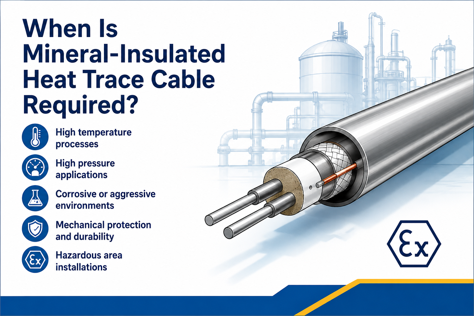
Engineered Metal-Sheathed Heater
The conductor, mineral insulation, sheath, cold leads and terminations form a designed heating unit.
1. High Maintain or Exposure Temperatures
MI cable is frequently selected where the operating or exposure temperature is above the rating of suitable polymeric heating cables.
- High-temperature chemical and petrochemical lines
- Hot process transfer pipework
- Steam-cleaned or steam-purged equipment
- Bitumen, sulphur and heavy-product lines
- Vessels, reactors and process equipment
- Applications exposed to high temperatures while the heater is de-energised
Check Two Temperature Limits
The required maintain temperature and the maximum exposure temperature are different design values. Cable, joints, cold leads and terminations must all remain suitable for the highest credible operating, cleaning, upset or shutdown condition.
2. High Output and Controlled Heat-Up Duties
A system that must raise the temperature of a cold pipe, vessel or process product within a defined period can require substantially more power than a steady-state maintenance duty.
The starting point is an accurate heat-loss and heat-up assessment. MI cable may then be selected where a high engineered output is required and the equipment can safely accept the resulting sheath temperature.
High-output design must consider:
- Steady-state heat loss
- Initial and final temperatures
- Product mass and specific heat capacity
- Required heat-up time
- Maximum permissible surface and sheath temperatures
- Cable spacing and heat distribution
- Temperature control and independent limiting
3. Long Circuits and Engineered Resistance
MI heating cable is a series-resistance heater. Its resistance, length, conductor material and supply voltage are selected together to produce the required output.
This engineered approach can be useful for long pipe runs or duties where parallel-circuit cable limits would require multiple shorter circuits. However, a long MI circuit is not automatically the best solution; voltage, output distribution, cold leads, power supplies and control architecture must all be assessed.
4. Harsh Industrial Environments
The metal sheath and mineral insulation can provide strong resistance to heat, fire and mechanical damage. Different sheath alloys are available for different corrosive environments.
| Environmental Requirement |
Why MI May Be Considered |
| High ambient or process heat |
Metal and mineral construction can tolerate temperatures beyond many polymeric cables |
| Mechanical exposure |
Metal sheath provides robust protection, subject to routing and bend-radius limits |
| Chemical or corrosive atmosphere |
A suitable sheath alloy can be selected for the environment |
| Fire resistance |
Inorganic insulation and metal construction offer strong high-temperature stability |
| Outdoor or offshore service |
Engineered sheath, joints and terminations can suit severe environments |
| High-pressure or critical process plant |
Factory-engineered assemblies provide controlled resistance and documented construction |
Sheath selection must be based on the actual chemical exposure. No single metal alloy is universally resistant to every acid, chloride, sulphur compound or process contaminant.
5. Mineral-Insulated Trace Heating in Hazardous Areas
MI heaters are available as certified systems for explosive atmospheres, but the complete assembly must be selected and installed for the area classification.
- Area classification and equipment protection level
- Gas or dust group
- Temperature class or maximum surface temperature
- Stabilised design or controlled design method
- Approved joints, cold leads, glands and enclosures
- Controller and independent temperature limiter requirements
- Ambient, maintain and exposure temperatures
View the ATEX trace heating range and obtain technical confirmation for the proposed MI assembly.
MI Cable Compared with Self-Regulating and Constant Wattage Cable
| Selection Factor |
Mineral-Insulated |
Self-Regulating |
Constant Wattage / Resistance |
| Typical reason for selection |
High temperature, high output, long engineered circuit or severe environment |
Variable-temperature response and convenient field installation |
Defined output and controlled process heating |
| Construction |
Metal conductor, mineral insulation and metal sheath |
Parallel bus wires with conductive polymer core |
Parallel heating zones or series resistance conductor |
| Field cutting |
Normally supplied as an engineered heater unit |
Usually cut to length within product limits |
Depends on parallel-zone intervals or engineered series length |
| Local output response |
No self-regulating response |
Output changes locally with temperature |
Defined output when energised |
| Temperature control |
Engineered controller and often limiter required |
May still require controller or limiter |
Normally requires suitable control |
| Installation skill |
Specialist handling, termination and testing |
Commonly field terminated with approved kits |
Depends on cable construction and system design |
For a detailed comparison of the two common polymeric cable types, see self-regulating vs constant wattage trace heating.
When May MI Cable Not Be Required?
MI cable should not be specified simply because it is the most robust or highest-temperature technology available.
- Low-temperature frost protection may be served more simply by self-regulating cable
- A standard process-maintenance duty may fall comfortably within a polymeric cable range
- Complex valves and fittings may be easier to trace with a flexible parallel cable
- Projects requiring simple cut-to-length field installation may favour self-regulating or parallel-zone cable
- High output may be unnecessary when insulation can be improved
- The pipe or product may not tolerate the surface temperature associated with a high-output MI design
Select the Lowest Suitable Technology
The preferred cable is the one that meets the thermal, electrical, environmental and certification requirements with appropriate control—not automatically the cable with the highest temperature or output rating.
MI Trace Heating Design and Installation Considerations
- Calculate the duty: establish steady-state heat loss and any heat-up requirement.
- Confirm temperatures: maintain, maximum exposure, ambient and permitted sheath temperatures.
- Select sheath material: match the alloy to the chemical and mechanical environment.
- Design resistance and length: coordinate voltage, conductor resistance, cable length and output.
- Plan cold leads and joints: position transitions and enclosures within their temperature limits.
- Specify control and limiting: use sensors, controllers and independent limiters where required.
- Check installation geometry: bend radius, spacing, attachment and heat distribution are critical.
- Test throughout installation: complete the specified resistance and insulation checks before and after insulation.
- Document the heater: retain factory data, circuit drawings, settings and commissioning readings.
Mineral-Insulated Heat Trace Cable Selection Checklist
Provide these details for design:
- Pipe, vessel or equipment dimensions and material
- Required maintain temperature
- Minimum ambient temperature
- Maximum operating, cleaning and upset temperature
- Insulation material and thickness
- Required heat-up time, where applicable
- Available voltage and power-supply arrangement
- Required circuit length
- Chemical, corrosion and mechanical exposure
- Safe-area or hazardous-area classification
- Control, alarm and temperature-limiting requirements
- Preferred junction-box and cold-lead locations
Explore the available mineral-insulated trace heating cables and engineered systems.
Mineral-Insulated Heat Trace Cable FAQs
Is MI Cable Only Used for Very High Temperatures?
No. High temperature is a common reason for selecting MI, but high output, long engineered circuits, fire resistance, mechanical strength and chemical resistance can also influence the decision.
Can Mineral-Insulated Heating Cable Be Cut to Length on Site?
MI heaters are normally designed and manufactured to a specific resistance, length, voltage and output. They should not be treated as bulk cut-to-length parallel cable.
Does MI Cable Require a Thermostat?
A suitable controller is normally required, and an independent temperature limiter may also be necessary where maximum sheath or surface temperature must be controlled. The exact arrangement comes from the system design.
Can MI Heating Cable Be Used in Hazardous Areas?
Yes, certified MI heater systems are available. The complete assembly, controls, terminations and installation must match the area classification and certification conditions.
Is MI Cable More Durable Than Polymeric Heating Cable?
Its metal sheath and inorganic insulation can provide excellent heat, fire and mechanical resistance. Durability still depends on choosing the correct sheath alloy, installing it within bend limits and protecting joints and terminations.
When Should Self-Regulating Cable Be Chosen Instead?
Self-regulating cable may be more suitable for lower-temperature frost protection, irregular pipework, changing ambient conditions and projects requiring straightforward cut-to-length installation.
Need an Engineered MI Trace Heating System?
Thorne & Derrick supports mineral-insulated heating cable selection for high-temperature, high-output, long-line and hazardous-area applications.
- Heat-loss and heat-up calculations
- MI heater resistance and circuit design
- Sheath alloy and temperature selection
- Cold leads, joints and terminations
- Controllers and temperature limiters
- ATEX and IECEx system specification
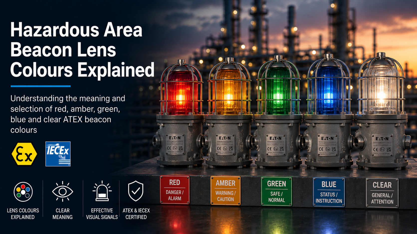
Hazardous area beacon lens colours help personnel distinguish between alarms, warnings, equipment states and process conditions. Red, amber, green, blue and clear signals can each communicate a different message when used within a properly defined alarm philosophy.
However, a beacon colour does not have one fixed meaning in every industry or on every site. The intended response should be established through the project specification, operating procedures and site-specific visual signalling system.
Thorne & Derrick supplies hazardous area ATEX beacons in a range of lens and signal colours, with LED, xenon, steady, flashing, strobe and electronically rotating options.
For a general introduction to hazardous area visual signalling, read What Is an ATEX Beacon?
Key principle: select the beacon colour from the documented site alarm philosophy. Do not assume that a colour automatically represents the same condition across every plant, industry or country.
Hazardous Area Beacon Colour Meanings
The table below summarises common industrial interpretations. These meanings are indicative only and must be checked against the site alarm philosophy.
| Beacon Colour |
Common Interpretation |
Example Applications |
Required Response |
| Red |
Danger, emergency, serious alarm or stop condition |
Fire alarm, gas alarm, emergency shutdown or hazardous machine state |
Immediate attention or action may be required |
| Amber or Yellow |
Warning, caution, abnormal condition or awareness |
Equipment about to start, process deviation, restricted area or potential hazard |
Check conditions and proceed with caution |
| Green |
Normal, safe, available, ready or action completed |
Equipment operating normally, safe access or alarm acknowledged |
Normal operation or a safe condition may be indicated |
| Blue |
Change, specific status, instruction or security-related condition |
Equipment powering down, security alarm or site-specific process state |
Follow the documented site instruction |
| Clear or White |
General attention, location, visibility or project-specific indication |
General notification, obstruction indication or equipment identification |
Confirm the intended meaning from the site documentation |
Do not rely on this table alone: the signal meaning should be formally defined, documented and communicated to site personnel. A manufacturer’s available colour does not determine how it must be used.
What Does a Red Beacon Indicate?
Red is commonly associated with danger, emergency, fire, a serious process alarm or a condition requiring immediate attention.
A flashing red beacon generally creates a stronger warning message than a steady red signal. However, the response must be determined by the documented alarm system rather than the colour and signal mode alone.
Common Red-Beacon Applications
- Fire or gas detection alarm
- Emergency shutdown condition
- Evacuation warning
- Dangerous machine or process state
- Live or energised equipment warning
- Critical fault requiring immediate response
Avoid conflicting meanings: if red is reserved for fire or evacuation alarms, it should not also be used for routine equipment status without a clear and documented distinction.
What Does an Amber or Yellow Beacon Indicate?
Amber and yellow are commonly used for warnings, caution, abnormal conditions or situations requiring increased awareness.
The signal may indicate that equipment is about to start, a process is outside its normal range or a potential hazard is developing but has not reached an emergency condition.
Common Amber-Beacon Applications
- Machinery preparing to start or move
- Process deviation or developing fault
- Temporary restriction or caution area
- Reduced visibility or environmental warning
- Maintenance or inspection attention required
- Non-critical plant alarm
Amber vs Yellow
Manufacturers do not always use amber and yellow terminology in exactly the same way. One datasheet may describe the lens as amber while another refers to the corresponding emitted LED colour as yellow.
Always use the exact manufacturer colour description and ordering code when requesting a quotation.
What Does a Green Beacon Indicate?
Green is commonly used to indicate a normal, safe, available or correctly operating condition.
It can also show that an alarm has been acknowledged, corrective action is under way or equipment is ready for operation.
Common Green-Beacon Applications
- Normal equipment operation
- Safe access or safe process condition
- System ready or available
- Corrective action completed
- Alarm condition acknowledged or controlled
- Plant status within defined operating limits
Green should not be used where personnel could mistake it for an unrestricted safe condition when a residual hazard remains.
What Does a Blue Beacon Indicate?
Blue is often used for a specific instruction, change in condition, security-related alarm or site-defined process state.
Its meaning can be particularly site-specific. Personnel should therefore be trained to understand the response required when a blue signal is activated.
Possible Blue-Beacon Applications
- Equipment powering down or changing state
- Security or access-control alarm
- Operator action required
- Specific maintenance or process condition
- A signal that must remain distinct from red, amber and green conventions
External restrictions may apply: blue warning lights can have regulated meanings in transport and emergency-service environments. Check the installation location and applicable rules before selection.
Clear Beacon Lens vs White Signal
“Clear” and “white” do not always describe the same component.
A clear or transparent lens describes the colour of the dome or cap. A white signal describes the light emitted by the LED, lamp or flash source.
A clear lens may therefore be used with a white LED, xenon flash tube or another internal light source, depending on the product.
Common Clear or White Applications
- General attention or notification
- Equipment or obstruction indication
- Long-distance or high-visibility signal
- Area or equipment identification
- Project-specific alarm condition
Clear or white should not be treated as a neutral default without confirming what the signal is intended to communicate.
How Colour and Signal Mode Work Together
Personnel interpret the complete visual signal rather than the lens colour in isolation. A steady red light can communicate a different level of urgency from a rapidly flashing red strobe.
The meaning can be strengthened by combining colour with:
- Steady, blinking, strobe or rotating signal modes
- Different flash or rotation frequencies
- Audible alarm tones
- Text labels and identification plates
- Symbols or display messages
- Beacon position or location
Colour should be supported by these supplementary methods where relying on colour alone could create ambiguity.
Read Steady vs Flashing vs Rotating ATEX Beacons for a comparison of the principal visual signalling modes.
Do LED and Xenon Beacons Produce Colour Differently?
Yes. The method used to create the coloured signal can differ between LED and xenon products.
LED Beacon Colours
An LED beacon can use coloured LEDs, a coloured cap or a combination of the two. The wavelength, brightness and current consumption can vary between colours.
Xenon Beacon Colours
A xenon flash tube produces a broad-spectrum pulse of light. A coloured dome or lens filters that light to create the required signal colour.
The filtering effect can reduce the measured optical intensity compared with a clear lens. The reduction is product- and colour-specific.
Read LED vs Xenon ATEX Beacons for a wider comparison of the two technologies.
Does Beacon Colour Affect Visibility?
Colour can affect the apparent brightness, contrast and recognition of a beacon signal.
Visibility is influenced by:
- The LED, lamp or xenon flash output
- Lens colour and light transmission
- Viewing distance
- Direct sunlight and ambient illumination
- Background colour and visual contrast
- Mounting height and orientation
- Structures or equipment obstructing the signal
- Flash frequency or signal pattern
- The observer’s position and field of view
Product-specific performance: do not assume that one colour is always brighter than another. Current Eaton FHF dSLB20 LED data, for example, gives different approximate optical outputs for white, red, yellow, green and blue versions.
Should an Alarm Depend on Colour Alone?
Where a warning is safety-critical, the meaning should not depend unnecessarily on colour alone.
Lighting conditions, smoke, dirt, distance and differences in colour perception can all affect how the signal is recognised.
Supplementary methods can include:
- Different flash or rotation patterns
- Audible sounders with distinctive tones
- Text displays or alarm messages
- Symbols and equipment labels
- Clearly separated beacon positions
- Operator training and documented procedures
Explore the wider range of
hazardous area sounders, beacons and combination units
.
Hazardous Area Beacon Colour Examples
Available colours depend on the product technology and ordered configuration. The examples below illustrate three different signalling ranges.
MEDC FB11 & FL11
Steady visual signalling options include clear, red, blue, green, yellow and amber lens configurations, depending on the selected model.
View MEDC FB11 & FL11 steady beacons
Eaton FHF dSLB20 LED
Available signal colours include white, red, yellow or amber, green and blue, with transparent or coloured cap options depending on the configuration.
View the Eaton FHF dSLB20 LED signal light
Confirm colour availability against the current product datasheet and complete ordering code. Not every colour is available for every voltage, signal mode or approval.
How to Select a Hazardous Area Beacon Colour
Colour selection should take place after the hazardous area and technical requirements have been established.
- Confirm the site alarm philosophy. Identify what each colour already represents and avoid introducing conflicting meanings.
- Define the required response. Establish whether personnel must stop, evacuate, investigate, acknowledge or continue normal operation.
- Select the signal mode. Decide whether the condition requires steady, blinking, strobe or rotating indication.
- Assess visibility. Consider viewing distance, ambient lighting, mounting position, obstructions and background contrast.
- Check product performance by colour. Compare the manufacturer’s optical data for the exact LED or lens option.
- Confirm electrical requirements. Current consumption may differ between signal colours and operating modes.
- Confirm product availability. Check the selected colour against the required voltage, approval and ordering reference.
- Use supplementary coding. Support colour with sound, labels, symbols, position or signal pattern where required.
For the complete product-selection process, read
How to Select an ATEX Beacon
.
Information Required When Ordering
Include the following information when requesting a quotation:
Hazardous area zone
Gas or combustible-dust group
Temperature class and ambient range
LED, xenon or alternative technology
Steady, flashing, strobe or rotating mode
Required signal or lens colour
Operating voltage
Indoor, outdoor or offshore environment
Viewing distance and ambient lighting
Mounting and cable-entry requirements
Common Beacon Colour Selection Mistakes
Assuming that every site uses identical colour meanings
Selecting a colour before defining the required operator response
Using the same colour for emergency alarms and routine equipment status
Assuming that every colour produces the same optical intensity
Failing to distinguish between a clear lens and a white emitted signal
Relying on colour without a supplementary signal or documented procedure
Failing to confirm colour availability for the required voltage and certification
Hazardous Area Beacon Colour FAQs
Does a red beacon always mean fire?
No. Red commonly indicates danger or emergency, but its exact meaning must be defined by the site alarm philosophy. Some sites reserve red specifically for fire or evacuation.
Are amber and yellow the same beacon colour?
They are frequently grouped as caution or warning colours, but manufacturer terminology and exact optical characteristics can differ. Use the stated ordering colour and code.
Does a clear lens produce white light?
It can, but not automatically. Clear describes the lens or cap, while white describes the emitted light. Check the light source and product configuration.
Does lens colour affect beacon brightness?
Yes. Lens filtering and LED wavelength can affect the measured and apparent output. Check the manufacturer’s data for the exact colour.
Can different beacon colours use the same flash pattern?
Yes, but personnel must still be able to distinguish the intended conditions. Similar patterns and poor colour contrast can create confusion.
Does the lens colour determine the hazardous area zone?
No. Zone suitability is determined by the complete certification and equipment marking. Lens colour affects the visual signal but does not establish the hazardous area classification.
Need Help Selecting a Beacon Colour?
Send Thorne & Derrick the hazardous area classification, intended alarm meaning, signal mode, viewing conditions, voltage and required colour for product selection support.
CONTACT THORNE & DERRICK
Compare Hazardous Area Beacon Colours
Explore red, amber, green, blue and clear visual signalling options with LED, xenon, steady, flashing and rotating configurations.
VIEW THE HAZARDOUS AREA BEACON RANGE