SIL3 or Safety Integrity Level (SIL) is based on the value of risk reduction associated with a Safety Instrumented Function (SIF) protecting against a specific hazardous event, or how the risk has to be reduced to reach an acceptable level.
The determination of a SIL is based on quantitative and qualitative factors such as:
development process
safety life cycle management
Read the following article about SIL 3 to learn more about Safety Integrity Levels, the need for SIL 3, its determination and implementation costs.
The implementation of Safety Instrumented Systems (SIS) is a common way to address hazards.
The eventual need for such instrumented protection must always be determined. If needed, the appropriate Safety Integrity Level (SIL) must be identified in order to achieve the required level of safety.
This process is crucial for achieving safety.
As we will see, SIL 3 is the appropriate level in rare and quite dangerous situations.
Safety Integrity Levels SIL3
The Safety Integrity Level (SIL) is based on the value of risk reduction associated with a Safety Instrumented Function (SIF) protecting against a specific hazardous event, or how the risk has to be reduced to reach an acceptable level.
Therefore it is a relative level of risk-reduction provided by a safety function, and, in other words, provides a measurement of the performance of a Safety Instrumented Function (SIF).
In IEC 61508 Standard, safety is defined as “freedom from unacceptable risk of harm”, while risk is the combination of the probability of occurrence of harm and the severity of that harm (R=FxC, where F is the Frequency of accidents and C is their Consequences, evaluated as a cost; therefore R is defined as cost per time unit).
Not all of the functional safety standards provide the same requirements for given SIL’s. IEC 61508 defines four SIL’s, with SIL 4 the most dependable and SIL 1 the least.
SIL is a measure of reliability and risk reduction used in several international standards;
ANSI/ISA S84 (Functional safety of safety instrumented systems for the process industry sector)
IEC 61508 (Functional safety of electrical/electronic/programmable electronic safety related systems)
EC 61511 (Safety instrumented systems for the process industry sector)
IEC 61513 (nuclear industry)
IEC 62061 (safety of machinery)
EN 50128 (railway applications – software for railway control and protection)
EN 50129 (railway applications – safety related electronic systems for signalling)
EN 50402 (fixed gas-detection systems)
ISO 26262 (automotive industry)
MISRA, various (guidelines for safety analysis, modelling, and programming in automotive applications)
Defence Standard 00-56 Issue 2 – accident consequence
The determination of a SIL is based on quantitative and qualitative factors such as development process and safety life cycle management. For example, the safety lifecycle includes a hazard and risk assessment phase, in which all significant hazardous events have to be identified and then subjected to an assessment to determine the level of risk reduction required from a safety instrumented function (SIF) to achieve a target level of risk.
The SIL expresses the required risk reduction or performance for the SIF. This assessment, called SIL determination, defines the required performance or “target SIL” for the SIF, and a target Average Probability of Failure on Demand (PFD), representing the maximum value allowed in the range of a target SIL.
The SIL determination methods commonly used are: Safety Layer Matrix (SLM); Risk Graphs (RG); Layer of Protection Analysis (LOPA); Fault Tree Analysis (FTA); and Event Tree Analysis (ETA), and they are normally used in combination, with LOPA being the most commonly used by large industrial facilities, SLM the simplest, FTA and ETA the most flexible and therefore suitable to complex cases.
SLM and RG are used for initial screening assessments. Because of its flexibility and orientation to details, FTA is especially suitable for the reassessment needed when a SIL 2, SIL 3 or SIL 4 level is determined.
Generally speaking, the assignment of a SIL is made as follows: the risk associated with a specific hazard is calculated without the risk reduction effect of the SIF. Then, the risk determined is compared to a risk target considered acceptable. The risk reduction of the SIF must address the difference between the unmitigated risk and the tolerable risk, with the SIL target corresponding in a correlation relationship to the required risk reduction, where the greater the reduction required, the higher the required SIL.
The International Electrotechnical Commission’s (IEC) standard IEC 61508 groups the requirements into the two categories of hardware safety integrity and systematic safety integrity. According to the standard the requirements for both categories must be met for a device to achieve a certain SIL. For hardware safety integrity, the requirements are statistical, with specific targets to reach, as the maximum probability of dangerous failure and the minimum safe failure fraction. In IEC EN 61508, the requirements for PFD (probability of failure on demand) and RRF (risk reduction factor) for different SIL’s for low demand operations are:
SIL
PFD
PFD (power)
RRF
SIL 1
0.1-0.01
10-1 – 10-2
10-100
SIL 2
0.01-0.001
10-2 – 10-3
100-1000
SIL 3
0.001-0.001
10-3 – 10-4
1000-10.000
SIL 4
0.0001-0.00001
10-4 – 10-5
10.000-100.00
and for high demand of operation or continuous operation (Probability of failure per hour)
SIL
PFH
PFH (power)
RRF
SIL 1
0.00001 – 0.000001
10-5 – 10-6
100.000 – 1.000.000
SIL 2
0.000001 – 0.0000001
10-6 – 10-7
1.000.000 – 10.000.000
SIL 3
0.0000001 – 0.00000001
10-8 – 10-9
10.000.000 – 100.000.000
SIL 4
0.00000001 – 0.000000001
10-9 – 10-10
100.000.000 – 1.000.000.000
The Need For SIL 3
Need for a SIL 3 Safety Functionis rare at process plants.
At process plants, most SIF won’t require higher than SIL 1. For safety functions requiring above SIL 2, several questions have to be addressed, regarding the use of the correct formula for reliability calculation, the consideration of common cause failure, the use of the right method to select appropriate values for common cause factors, the inclusion of the contributions from human error in the calculation of PFD, the inclusion of all relevant factors in the assessment, the evaluation of the appropriateness of the methodology used (if suitable or not; RG, LOPA and SLM aren’t appropriate for SIL 3, which requires a review of the assessment with a fault tree.
In fact, the reassessment can lead to reassigning a SIL 3 requirement for the SIF to a target PFD in the range of a lower SIL, with a consequent reduction in both capital and operating costs).
SIL 3
When SIL 3 is necessary, the combination of hardware configuration and human interactions with the safety function must be accurately examined, with the determination of the demand frequency requiring particular attention and a systematic approach (through the use a demand tree), covering normal operation, abnormal operation, start-up, shutdown and demands initiated from outside the plant (loss of services, power, etc.), since these factors added together are very significant.
SIL 3 Determination
SIL 3 determination requires care.
Any prospective SIL 3 SIF demands reassessment. Three aspects of SIL determination deserve special mention for SIL 3: team competencies, alarms and personnel exposure.
With regards to team competencies, effective SIL determination requires input from many professionals, managed for example through meetings with a leader and representatives of all the relevant disciplines, chosen according to professional skills and personal attitudes, since they have to work well together. Such meetings can work well for initial screening purposes and may provide sufficient detail to justify SIL 1 safety functions, but for the higher SIL’s, requiring more details, appointing an independent professional to carry out the assessment could be more appropriate.
With regards to alarms, SIL determinations must consider potential risk reduction from operator response to alarms, which could be influenced by his availability at the time the alarm enters in function, by the eventually insufficient time to respond and by the number of alarms in function at the same time. It may be difficult for the operator to decide what to do, and every effort must be put in place to guarantee that he has all the proper directions to make the right decision and initiate the correct actions.
With regards to personnel exposure, and the potential consequences on the workers of a failure, there’s the need to consider the proportion of time that the person at risk may be in the area of the plant where an injury could occur, taking in consideration that, even if for a high hazard zone the proportion of the working day spent there is quite small (for example less than 10%), the person could be asked to go to the hazard area to investigate just when the incident occurs. In that case, the proportion changes drastically, because it would be in practice 100% of the time the hazardous event occurs.
Achieving SIL 3
Achieving and maintaining in the long term (that is to say, for the entire duration of the function) SIL 3 performance is a very hard task. As a consequence, when the need for a SIL 3 SIF is determined, the people involved in the Risk Reduction projects find themselves in the complex situation of demonstrating that SIL 3 performance is achieved by the combination of hardware and human interactions, such condition being very likely to be put in discussion at a further examination by company stakeholders or external regulatory authorities.
For example, one of the major implications of SIL 3 is that it requires a high degree of duplication, a condition that is related with what is described in international standards as “hardware fault tolerance.”, a requirement for continuous functioning (even if one or more faults occur) determining the need of more than one sensor and more than one means of output to guarantee that the function will continue to work in case of failures occurring between periodic tests. In addition, achieving the necessary PFDavg for SIL 3 (that is to say, in the range 0.001 to 0.0001) implies that the SIF’s unavailability to respond successfully over a 1 year (8760h) period can be maximum 8.76 hours or less, a value that must include the time when the organization is unaware that the function isn’t working.
Furthermore, SIL 3 is achieved only when the following four conditions are satisfied in the calculation of the PFD: 1)the failure rates used are those properly applicable to the situation, as direct field-failure ones; 2) an appropriate assessment of dependency is performed in order to guarantee that calculations are not grossly optimistic; 3) the unavailability of the function during testing is accounted for; and, especially, 4) the human interactions with the safety function are taken in consideration, because humans are involved in the maintenance, calibration and testing of SIF and the probability of mistakes by them (for example the same having little effect on a SIL 1 PFD) may make SIL 3 unachievable.
As a consequence, differently from a SIL 1 function, accurate design of the human tasks and assessment of the probability of human error (and its inclusion in the PFDavg calculation) are needed for a SIL 3 function. Such activities require specialist skills.
SIL 3 Costs
Compared to a SIL 1 function, SIL 3 features additional operating costs.
Those, for example incurred in proof testing duration and frequency, which is more frequent and longer than for a SIL 1 function because of the higher number of elements to test, of the greater complexity of the systems and the higher frequency of tests (SIL 3 proof test interval could be at least once a year but will depend on the proof test coverage achievable during the proof test of that SIF).
Conclusions
The Main Concepts with SIL 3 are the following:
SIL 3 is a Safety Integrity Level that is appropriate for very specific and rare situations, in which a high level of risk-reductionperformance by a SIF is required.
The actual need for SIL 3 must be determined through an accurate and thorough SIL determination, and through a reassessment, also in consideration of the additional costs associated with achieving and maintaining a SIL 3 level.
Achieving SIL 3 has severalimplications, among which designing the safety performance of the combination of hardware and human interactions, and therefore requires the involvement of specialists from various disciplines in the risk reduction project.
In conclusion, SIL 3 is at the same time a target and a challenge and approaching it entails the use of the best skills and know-how owned by individuals and organizations. When the need for a SIL 3 Safety Integrity Level is determined, technology and human behaviors must be fit to the challenging goal.
Achieving safety, as “freedom from unacceptable risk of harm”, must be a fundamental objective in every productive activity and SIL 3 is a new frontier in Risk Reduction.
Thorne & Derrick are Specialist Distributors of Hazardous Area & Explosion Proof Equipment with IECEx & ATEX Certifications to the onshore and offshore oil, gas, petrochemicals and process industries.
Explosion Protection (ATEX) & Functional Safety (SIL) Training Seminar By Pepperl + Fuchs, The Process Automation Specialists
By Chris Dodds : estimated reading time 3 minutes
Thorne & Derrick, The Explosive Atmosphere Experts, have registered to attend the latest Pepperl + Fuchs training seminar – as specialist distributors of Electrical, Mechanical, Process & Instrumentation Equipment to the hazardous area industries our Sales Engineers are committed to providing the highest levels of customer service.
We deliver this commitment through a thorough understanding of hazardous area classifications, explosion protection methods, legislation compliance and the relationships between electrical equipment, gas groups and temperature classes.
We recommend our clients, suppliers and supporters consider registering their attendance to this excellent “up-skilling” opportunity provided by Pepperl + Fuchs, The Process Automation Specialists.
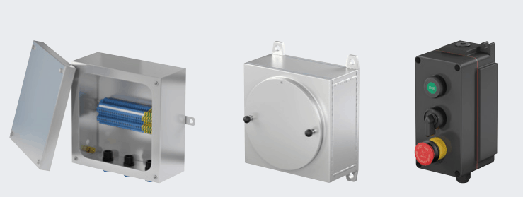
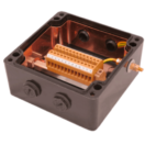
Thorne & Derrick distribute Pepperl+Fuchs Hazardous Area Electrical Equipment for the control of automation, machinery and electrical networks in harsh environments and potentially explosive atmospheres including control panels for Ex d Flameproof applications in hazardous areas with ATEX Certification.
type of protection “t”: functional principle and marking
consideration of the safety margins
SIL – EN 61508 & 61511
FREE Three ONE day SIL training seminars – 9am – 5pm
7th November 2016 – Teesside
9th November 2016 – Barton-upon-Humber
11th November 2016 – Oldham (9am – 4.15pm)
SEMINAR ITINERARY
1. Introduction
scope of EN 61508 and 61511
terms and definitions (risk, SIL, systematic and random failures, common misunderstandings with respect to SIL)
2. Risk Analysis
determination of basic risk and tolerable risk, quantification, minimum endogenous mortality
3. Failure performance of equipment
lifetime, MTBF, MTTR etc.; failure rates, difference between process technology and mechanical engineering, difference between electrical and mechanical equipment, Weibull-distribution
4. Avoidance of (systematic) failures
Functional Safety Management System, failure prevention and failure control, hardware fault tolerance, safety life cycle, documentation
5. Control of (unavoidable (?) and random)) failures
diverse and homogeneous redundancy, safe failure fraction SFF, diagnostic coverage DC, calculation of random failures
6. Proven in use
proven in use assessment according to NE 130 (German proposal)
7. Implementation of protective equipment
failure control acc. To EN 61511 – probability of failure on demand acc. To EN 61508
Please see the booking form PDF attached below.
BOOKING FORM – Complete for ALL seminars
We have curated a collection of our favourite Pepperl + Fuchs #AUTOMATION tweets – for more go to Twitter and Follow @PepperlFuchs
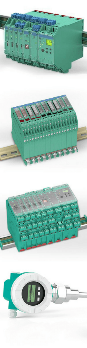
Process Automation & Electrical Equipment Product Range
Pepperl+Fuchs are leading suppliers of automation equipment for hazardous areas and process automation industries – the Pepperl + Fuchs product ranges includes intrinsic safety isolators, Zener barriers, signal conditioners, fieldbus technology, Remote I/O, HART interfaces, level measurement, purge and pressurization systems, Human Machine Interfaces (HMI) for hazardous environments, custom cabinets, and junction boxes.
Explosion Proof Electrical Enclosures & Control Stations – Ex e, Ex ia, Ex e Hazardous Areas
Invitation – network, engage, promote
Thorne & Derrick are inviting you to join LinkedIn’s fastest growing Discussion Group – Process & Hazardous Area Industries : Heat Tracing, Gas Detection, Fluid Control & Flow Measurement. News, projects, videos, promotions, whitepapers, jobs, webinars, press plus much more.
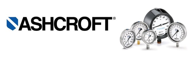
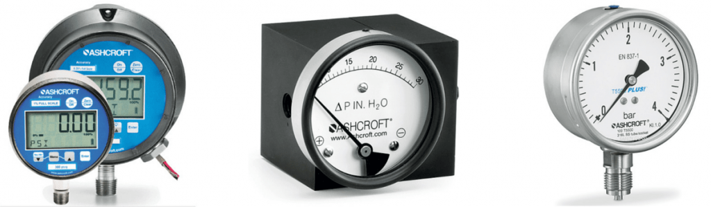
Ashcroftwas founded in 1852 by Edward Ashcroft and has developed into the world leading designer and manufacturer of pressure gauges used in many applications and industries – their instrumentation gauges were originally designed to protect the steam powered industry at the start of the industrial revolution in Great Britain.
“A world where your people, processes and profits are never at risk because Ashcroft measurement instruments are on the job.”
The Ashcroft vision is cemented by their mission of constantly pushing the limits of innovation to consistently deliver the world’s most trusted pressure gauges and measurement instruments.
Ashcroft pressure gauges provide accurate, reliable performance throughout global process and industrial markets.
Ashcroft Pressure Gauges OVERVIEW
The range of Ashcroft Process Pressure gauges includes:
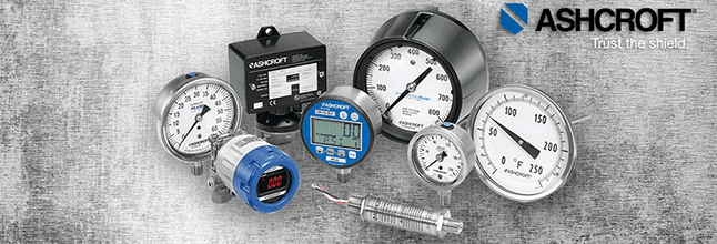
Ashcroft are the leading pressure and temperature instrumentation manufacturer of pressure gauges, test gauges and temperature gauges across all industries.
Ashcroft Pressure & Temperature Instrumentation – 160 Years Of Know-How & Experience
ashcroft Company History
Ashcroft protects assets and personnel in hundreds of countries – here are a few milestones in the Ashcroft company history:
1852 Edward Ashcroft acquired rights to produce Bourdon tubes
1852 Ashcroft Manufacturing Company is founded
1929 Introduced first phenolic gauge housing
1934 First to offer ±0.25% FS test gauge
1951 Moved world headquarters to Stratford, Connecticut
1973 Introduction of first precision digital pressure indicator
1977 Established Dresser Instruments Europe S.A. in Germany
1990 Cooperation with instrument manufacturer Nagano Keiki
1998 Developments in Ashcroft gauges, including PLUS!™ Performance™, Duratube™, FlutterGuard™, PowerFlex™movement and True Zero™
2016 & Beyond Ashcroft continues to introduce new, state-of-the-art instruments designed to meet their customer’s requirements
Industries
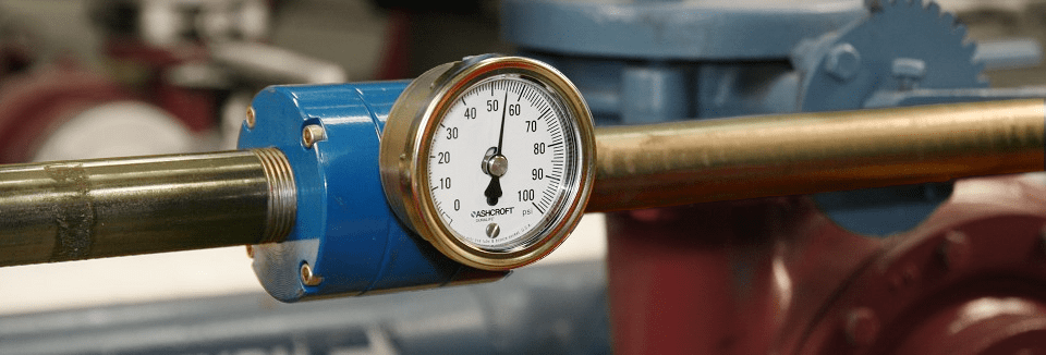
Applications for Ashcroft pressure gauges are extremely diverse with their pressure and temperature instrumentation being used to reduce costs and maintain the highest standards of process safety and environmental protection.
Ashcroft provide process temperature and pressure measurement instruments for industries including oil and gas, offshore, petrochemical, waste water, paper/pulp, renewable energy, power plants and mining/minerals industries.
Call us for Ashcroft Pressure & Temperature Measurement Instruments and Gauges.
Oil And Gas – Upstream, Mid-Stream & Downstream
Typically, Ashcroft instruments are divided by their application into three categories: 1) industrial and life 2) food and beverage 3) medical services.
Within these areas, there are more specific industries and applications to choose from. All of which is designed to make selecting the correct pressure gauge as simple as possible.
Ashcroft pressure gauges and process instruments are designed to perform in harsh conditions and are often deployed in the the wellhead, offshore rig and shale field – this includes NACEcompliant gauges, seals and SIL 3 capable switches.
Ashcroft provide pre-assembled gauges instrument/diaphragm seal combinations to ensure that corrosive caustics will not threaten any operation or personnel.
Within many industries, Ashcroft products provide filtration, pressure, flow and level measurement all requiring precise, continuous monitoring and control whilst also overcoming corrosive media, effluents, solids, vibration and pulsation. Constantly providing accurate measurements that prevent unplanned shutdowns and dangerous conditions.
Power Industry
Within the power industry, Ashcroft pressure gauges are used to help meet the demand for low energy prices, green energy production and a consistent, reliable service. The range of pressure measurement instruments have been developed to help sustain a power plant that is clean burning, efficient and in continuous service.
Ashcroft pressure gauges can monitor pressure levels in harsh environments and control pressure under the most extreme conditions. In hazardous area locations, safety is assured with Ashcroft explosion proof pressure switches certified to international hazardous Class/Division/Zone classifications.
MetaLs, Minerals And Mining Industry
Within the mining industry, Ashcroft products can help control damage before it occurs. Ashcroft focus is to protect lives, plant and equipment and countering everyday hazards that are naturally associated with this industry.
Purpose built pressure gauges for use in hazardous areas and destructive processes are suitable for use when dangerous gases are present and explosive atmospheres are commonplace. Even when monitoring the pressure of medias that are likely to clog a gauge, this can be overcome through an isolation ring, ensuring an uninterrupted process flow with continuously accurate measurements.
Pressure Gauges: NACE SIL ATEX Compliant
Ashcroft Social Media
Folllow Ashcroft on Twitter and LinkedIn for daily updates, new product information and discussions.
Ashcroft Pressure Gauges – Engage On Social Media Social
Thorne & Derrick are inviting you to join LinkedIn’s fastest growing Discussion Group – Process & Hazardous Area Industries : Heat Tracing, Gas Detection, Fluid Control & Flow Measurement. News, projects, videos, promotions, whitepapers, jobs, webinars, press plus much more.
Press Release Date: 02.04.2020 uploaded by Chris Dodds (T&D Sales + Marketing Manager) World’s First Fully Certified ATEX Doors Thorne & Derrick International, the Experts in Equipment for Explosive Atmospheres, today announce the signing of a Commercial Distribution Agreement...
Press Release Date: 04.07.2019 uploaded by Chris Dodds (T&D Sales + Marketing Manager) Category: Stockist Distributor Agreement Announcement Thorne & Derrick International announce that they have signed a Preferred Distributor Agreement with Raytec, the world leading manufacturer of LED...


 For further technical information see |
 distributors of Electrical, Mechanical, Process & Instrumentation Equipment to the hazardous area industries our Sales Engineers are committed to providing the highest levels of customer service.