T&D : Largest UK Stockist of Heat Trace Tapes & Cables
uploaded by Chris Dodds – Thorne & Derrick Sales & Marketing Manager
Heat Trace Tape
Heat tape, is the term traditionally used to describe a common heat tracing cable or heating cable. The limited flexibility of “traditional” heat tape can make applying to small diameters of pipework or complex shapes difficult.
The good news is there is a more flexible solution available. Introducing, BriskHeat’s XtremeFLEX® Heating Tapes. These trace heating cablesare truly flexible and can be easily wrap around objects as small as a pencil!
Unlike “traditional” heat trace tape, XtremeFLEX® heating tapes can be easily removed and re-installed in a variety of applications. These re-usable heating tapes are the perfect tool for unexpected maintenance, where quick heat is needed. Below are 5 benefits of truly flexible XtremeFLEX® heating tapes.
These heating tapes can be used as an efficient solution for your freeze protection, viscosity control or process maintenance problems.
XtremeFlex Flexible Heating Tapes
Heat Trace Tape – The 5 Benefits
Benefit 1: Easily Wraps Around More Objects
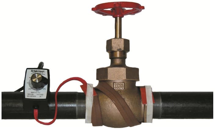
Whether your application is a small diameter pipe, laboratory glassware, a valve, or a complicated piece of machinery, XtremeFLEX® heat trace tapes are easy to install and even easier to operate.
Flexible Heat Tape Easily Wraps Around More Objects
The patented heating element and structural design gives the tapes the ability to accommodate a variety of applications with less installation hassle than other heat trace solutions.
The durability and flexibility of XtremeFLEX® heating tapes allows them to twist, turn, bend and wrap around many objects. XtremeFLEX® heating tapes is easy to install, quick fix for unexpected maintenance control problems.
Benefit 2: Provides More Intimate Contact with the Application
With XtremeFLEX® heating tapes, achieving intimate contact with a variety of objects is not a problem. Having a tape that provides intimate contact with the application allows more heat to be transferred to the object and less heat lost to the air.
XtremeFLEX® heating tapes have the ability to contour to the surface and shape you are heating with more intimate contact and surface coverage than traditional surface heating products. Providing intimate contact ultimately reduces both the objects heat-up time and your production down-time.
Heating Tape Provides More Intimate Contact With The Application
Benefit 3: Faster Heat-Up
XtremeFLEX® heating tapes provide results quickly unlike other heat trace solutions. BriskHeat’s heating tapes are manufactured to have a more rapid heat-up time. XtremeFLEX® heating tapes have a high watt density, which allows them to heat-up quicker and heat up to higher temperatures. The rapid heat-up time makes for a more efficient and less time consuming solution for your application.
Benefit 4: Heating Cables Reach Higher Temperatures
XtremeFLEX® heat tracing cables have the ability to reach temperatures up to 760°C (1400°F). These flexible heating tapes are the ideal solution for any application that requires high temperatures quickly. The faster heat-up times and higher temperatures make XtremeFLEX® heating tapes suitable for a wide variety of applications.
Benefit 5: Durable & Long Lasting Heat Trace Cable Solution
XtremeFLEX® heating tapes are designed to be durable and long lasting. These XtremeFLEX® heating tapes are manufactured with a multi-strand resistance wire technology. This core technology provides durability for a long service life.
Heating Tapes
The multi-strand resistance wire provides flexibility for the heating tapes to be twisted, turned, bent and wrapped around objects without losing or shape. You can be confident that these truly flexible tapes have the durability and high performance standards for industrial use.
Flexible Heat Tape Provides A Durable Long Lasting Solution
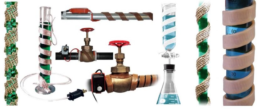
BriskHeat’s XtremeFLEX® heating tapes can be used on a wide range of applications. BriskHeat offers three types of flexible heating tapes that are sure to fit your heating needs. The three types of XtremeFLEX® Flexible Heating Tapes available are: moisture and chemical resistant mid-temperature silicone rubber heating tape, high-temperature cloth heating tape and small diameter high-temperature heating cord.
Silicone Rubber, Cloth Tape And Heating Cord Heat Trace Cable
Don’t be traditional when you could use the benefits of BriskHeat’s XtremeFLEX® heating tapes to your advantage. Heat your applications quickly and efficiently with XtremeFLEX® heating tapes!
XtremeFLEX® heating tapes wrap around objects with diameters as small as ½ inch (12mm). They truly are flexible tapes that are easy-to-use and even easier to install.
They are the perfect tool for unexpected maintenance, where quick heat is needed. Easily remove and re-install the flexible heating tapes when an unexpected maintenance application occurs.
XtremeFLEX® heating tapes are the ideal solution for any application that requires high temperatures fast.
Built for long-lasting use in any environment, no matter the application, there is a heating tape for you.
➡ Contact Thorne and Derrick About Your XtremeFLEX® Heating Tape And Trace Heating Applications
How To Easily Select and Install Heating Tape
EXPERTS IN WINTERISATION SOLUTIONS FOR INDUSTRIAL & HAZARDOUS AREA ENVIRONMENTS
Thorne & Derrick hold the largest UK stocks of frost protection & winterisation equipment to help keep your plant and personnel operational during the winter months.
Thorne & Derrick understand that prolonged periods of low ambient temperatures can bring operations to a standstill costing thousands of pounds in lost downtime.
Experts in heating solutions for use in industrial & explosive atmospheres, Thorne & Derrick have the knowledge & expertise to help clients prevent unnecessary down time this winter.
We can provide overnight delivery of Trace Heating Cables at the most competitive prices to guarantee frost protection of your pipelines and mechanical services.| Ask About Our Heat Trace Design Service.
💡 Contact us today and our skilled and friendly team can provide technical support as well as reliable, fit for purpose and compliant solutions to suit your exact requirements.
➡See our Winterisation blog TOP PICKS, including our most read articles about Trace Heating and the requirement for electrical heating products and systems to combat and mitigate Winter weather effects.
IBC Heater Jackets In The Food And Beverage Industry
By Chris Dodds : estimated reading time 5 minutes
IBC Heaters
T&D are major distributors of IBC Container & Process Heating Products to the food and beverage industry supplying major customers with bespoke solutions to overcome heating challenges faced with consistent and reliable production – our range of IBC heaters provide reliable surface heating to bulk containers ensuring optimum contents viscosity, frost protection and temperature maintenance.
The range of Electrical Process & Drum Heating products that T&D supply can be used to ensure consistency, hygiene and guaranteed plant performance which is absolutely vital in the food processing industry.
IBC heating jackets and systems provide effective electric surface heating for food industry containers and drums:
Dairy
Beverages
Tea, Coffee & Cocoa
Bakery (Flour, Yeast, Bread products)
Breakfast Cereals
Soups & Sauces
Flavours & Fragrances
Colourants
Nutraceuticals
Common heating applications include IBC’s, containers or drums storing honey, corn sugar, palm oil and molasses.
Explosive Dust Atmospheres
Powders including flour and sugar are routinely stored on site at bakeries – when mixed with air, they can form a potentially explosive mixture and are classified as Zones 20 / 21 under ATEX guidelines.
T&D distribute ATEX IBC heaters for safe use in both hazardous area gas (Zone 1 & Zone 2) and dust (Zones 20, 21 & 22) atmospheres – typical food industry applications include wheat starch, gluten, wheat gluten production, grain processing and sugar production.
Other combustible dusts include:
Most solid organic materials (wood, flour, grass, paper, cereals, etc.)
Many powdered metals (such as aluminium, magnesium and titanium)
Certain non-metallic inorganic materials (although less common)
Low Voltage IBC Heaters
Fox’s Biscuits
Thorne & Derrick are distributors and stockists of low voltage IBC heating jackets which provide a consistent heating solution at safe low voltages of either 24V or 48V.
Low voltage IBC heating jackets have been used in the past in a case study for Fox’s Biscuits. Fox’s Biscuits manufacture a wide range of premium quality biscuits within the UK and are part of the Northern Foods PLC.
The client required a heating method to maintain an IBC containing glucose at 35ºC to ensure consistent flow during production and had previously used trace heating to achieve this but found that heat tracing cables did not provide an even temperature across the large surface area of the IBC.
To provide a more suitable solution a low voltage IBC heater jacket was provided which wrapped around the IBC covering the entire surface area, along with an insulated PVC lid. Additionally, custom sized low voltage heater jackets were supplied to fit around 40 metres of associated process pipework.
Using IBC heater jackets, the client was able to achieve a constant heat, ensuring the glucose could be fed through the pump and at the optimum temperature production.
Sugar Glucose – sugars provide sweetening, texture, bulk, colour and act as preservative agents in the food and beverage industry.
Low Voltage IBC Heater Jacket Benefits
Accurate temperature control and monitoring
Even temperature distribution across the IBC container – no hot or cold spots
Safe – Low Voltage (24V-48V ac)
Low Power Consumption – provides energy cost savings – up to 72% reduction
T&D also provide heat tracing cables for the temperature maintenance of food industry process pipework.
IBC Heating Jackets Used To Heat Up Caramel
IBC Heaters – HIBC/A
T&D have supplied Nestle Bulgaria with an IBC heater to heat up liquid caramel. Our client required a process heating method to maintain the temperature of the caramel between 40 and 50ºC to reduce the viscosity of the caramel and approached T&D to supply IBC heating jackets.
The client held the caramel within ‘bag-in-a-box’ style IBC containers to which HIBC/A IBC heating mats are ideal for providing surface heating.
HIBC/A silicone IBC heater mats are placed underneath the container before filling and provide heat through the container. Insulated IBC jackets and insulated lids help to reduce heat loss from the container.
HIBC/A heating mats have a PTC temperature sensor which can be connected to a digital temperature controller to allow for accurate monitoring and control of the temperature.
Bag In A Box – IBC Heaters
Bag In Box IBC Heaters
Bag in box IBC systems offer safety and hygiene with replaceable liner bags – the reusable bulk container protects the liquid contents providing ideal transportation conditions. T&D provide IBC heating jackets to suit all type of plastic or steel containers.
EXPERTS IN WINTERISATION SOLUTIONS FOR INDUSTRIAL & HAZARDOUS AREA ENVIRONMENTS
Thorne & Derrick hold the largest UK stocks of frost protection & winterisation equipment to help keep your plant and personnel operational during the winter months.
Thorne & Derrick understand that prolonged periods of low ambient temperatures can bring operations to a standstill costing thousands of pounds in lost downtime.
Experts in heating solutions for use in industrial & explosive atmospheres, Thorne & Derrick have the knowledge & expertise to help clients prevent unnecessary down time this winter.
We can provide overnight delivery of Trace Heating Cables at the most competitive prices to guarantee frost protection of your pipelines and mechanical services.| Ask About Our Heat Trace Design Service.
💡 Contact us today and our skilled and friendly team can provide technical support as well as reliable, fit for purpose and compliant solutions to suit your exact requirements.
➡See our Winterisation blog TOP PICKS, including our most read articles about Trace Heating and the requirement for electrical heating products and systems to combat and mitigate Winter weather effects.
Devices for use in potentially explosive atmospheres have to be marked. The requirements on markings come from different sources. So EU Directive 94/9/EC (ATEX 95) stipulates in Europe, which information has to be given on the type label.
These are the minimum requirements that have to be supplemented by further information required for safety. The required safety-relevant data and their order on the type label are stipulated in the European standards.
The requirements on electrical devices for use in explosive gas atmospheres are included in standard series EN 60079. For devices that are intended for use in areas with combustible dust standard series EN 61241 has to be applied.
For many years now these standards have been prepared on an international level by the IEC and then adopted as European standards.
Up to now marking has been specified in IEC 60079-0 / 2004 and in IEC 61241-0 / 2004. To clearly identify the device, the type identification and the serial number have to be stated as well as, the manufacturer’s name or his trademark.
For devices subject to certification the name of the notified body issuing the certificate and the certification number have to be given. Additionally, a special coding is required that describes the applicable use of the device:
the symbol for an Ex explosion-protected device
the symbol of each type of protection that has been applied
group IIA, IIB or IIC for explosive gas atmospheres
temperature class for explosive gas atmospheres or the maximum surface temperature in °C for areas with combustible dust.
Examples:
Ex d e IIC T4
Ex d [ia] IIB T5
Ex pD21 T120 °C
With associated electrical equipment in type of protection intrinsic safety that is to be installed in the safe area, the symbols for this type of protection have to be put into square brackets, e.g. [Ex ia] IIC.
If the equipment is to be mounted in hazardous areas it has to be protected by another type of protection. Then only the mark for intrinsic safety is put into square brackets, e.g. Ex d e [ib] IIC T6.
In the past, the marking pursuant to the European standard changed from ›Ex‹ to ›EEx‹. This was done to relate to the European standards (EN 50014 serie) that then differed from the IEC-standards.
With the current state of the standards this is no longer required so that in Europe the new devices are only marked ›Ex‹ as well.
From the previous marking the protection level of the device in regard to explosion protection cannot be clearly seen right away. Only knowledge of the possible application of the different types of protection indicates the application of the device in the respective zones.
This problem was noticed in Europe at an early stage. So with the European Directive 94/9/EC (ATEX 95) the equipment categories 1, 2 and 3 were introduced. Transfer of these categories from the Directive to the standards, however, has only been done in the EN-standards and not in the IEC-standards.
Table 1: Marking and definition of Equipment Protection Level EPL
EPL Ga
Equipment for explosive gas atmospheres, having ensuring a “very high” level of protection for use in explosive gas atmospheres, which is not a source of ignition in normal operation, during expected malfunction, or during rare malfunction
EPL Gb
Equipment for explosive gas atmospheres, having ensuring a “high” level of protection, which is not a source of ignition in normal operation or during expected malfunctions
EPL Gc
Equipment for explosive gas atmospheres, having ensuring an “enhanced” level of protection, which is not a source of ignition in normal operation and which may have some additional protection to ensure that is remains inactive as an ignition source in the case of regular expected occurrences (for example failure of a lamp)
EPL Da
Equipment for explosive dust atmospheres, having ensuring a “very high” level of protection for use in explosive gas atmospheres, which is not a source of ignition in normal operation, during expected malfunction, or during rare malfunction
EPL Db
Equipment for explosive dust atmospheres, having ensuring a “high” level of protection, which is not a source of ignition in normal operation or during expected malfunctions
EPL Dc
Equipment for explosive dust atmospheres, having ensuring an “enhanced” level of protection, which is not a source of ignition in normal operation and which may have some additional protection to ensure that is remains inactive as an ignition source in the case of regular expected occurrences (for example failure of a lamp)
New marking
In the IEC 60079-0 / 2007 the devices for use in explosive dust atmospheres have been included. So the general requirements on devices for use in explosive gas and dust atmospheres are covered in this standard.
Marking has now been supplemented with the protection level of the equipment. This equipment protection level (EPL) consists of two letters. The first one gives information on the type of explosive atmosphere: G for gas, D for dust.
The actual protection level is defined by the letters a, b or c (table 1). These letters are already used for some types of protection to mark the respective protection level: ia, ib, ic.
The symbol for the equipment protection level is added to the existing standard marking: example: Ex d e IIC T4 Gb. With associated electrical equipment, the EPL-symbol has to be mentioned after the type of protection: example: [Ex ia Ga)] IIC.
When an associated electrical equipment with an intrinsically safe circuit ia has been fitted into a flameproof enclosure, for example, make it possible to install it into Zone 1, the following marking is required: Ex d [ia Ga] IIC T4 Gb.
Groups
The suitability of devices for use in different hazardous areas is determined by groups. Up until now two groups have been defined: devices intended for use in mines at risk through firedamp belong to Group I.
Group II stands for devices that may be used in areas other than mines, specifically areas that are at risk through flammable gas.
Further sub-division of this Group II into three sub-groups IIA, IIB and IIC determines which type of gas the device is suitable for. With the IEC 60079-0 / 2007 a new group III has been introduced.
It stands for devices that are intended for areas in which an explosive dust atmosphere may be expected. Devices have to meet different requirements for different dusts. So, similarly to Group II, further sub-division are also planned for Group III:
Thus the devices can be assigned to the different types of dust and their different requirements.
Example: Ex tb IIIC T120°C Db.
Table 2: Comparison of the different markings according to IEC 60079-0
Old Marking
New Marking
Alternative Marking
Ex d IIB T4
Ex d IIB T4 Gb
Ex db IIB T4
Ex de IIC T4
Ex de IIC T4 Gb
Ex db eb IIC T4
Ex ia IIC T4
Ex ia IIC T4 Ga
Ex ia IIC T4
Ex d [ia] IIC T6
Ex d [ia Ga] IIC T6 Gb
Ex db [ia] IIC T6
Ex tDA21 IP65 T225ºC
Ex tb IIIC T225ºC Db
Ex tb IIIC T225ºC
Alternate marking
Standard IEC 60079-0 / 2007 allows alternative marking to the one described in the previous chapter, which gives information twice in some cases.
With the introduction of Group III the suitability of a device for gas atmospheres (II) or dust atmospheres (III) can be seen directly through the group number. So the letter G or D in the equipment protection level does not give additional information.
With some types of protection the protection level is marked by supplementing the letters a, b or c to the symbol of the type of protection. Alternate marking intends to add this distinguishing letter to all types of protection.
E.g., flameproof enclosures ›d‹ will then be marked ›db‹. This then clearly shows the application range of a device in regards to the potentially present explosive atmosphere and the protection level without stating the EPL. So EPL marking can be omitted.
Example:
Ex db eb IIC T4
Ex db [ia] IIB T5
Ex tb IIB T120°C
Table 3 shows the currently possible alternate marking of the different types of protection. Old, new and alternate marking is shown in table 2.
The manufacturer may decide which marking he will use. However, the alternate marking seems to be more coherent as redundant information are eliminated.
Table 3: Symbols of the type of protections according to the alternate marking
Type Of Protection
Use For Gas Atmospheres
Use For Dust Atmospheres
Zone 0
Zone 1
Zone 2
Zone 20
Zone 21
Zone 22
Flameproof Enclosures
db
Increased Safety
eb
Intrinsic Safety
ia
ib
ic
ia
ib
Encapsulation
ma
mb
mc
ma
mb
mc
Oil-Immersion
ob
Power Filling
qb
Pressurised Enclosure
pxb, pyb
pzc
pb
pc
Protection by Enclosure
ta
tb
tc
Non-Sparking Device
nAc
Devices and Components
nCc
Restricted Breathing Enclosures
nRc
Marking according to ATEX 95
In Europe, in addition to the marking according to standard, the requirements according to EC Directive 94/9/EC (ATEX 95) have to be fulfilled.
ATEX 95 Directive Annex II requires the following marking:
name and address of the manufacturer
serial number, year of manufacture
mark with the identification number of the notified body
Ex and category 1, 2 or 3
and for Group II the letter G (gases) or D (dust)
Example: Ex 2 II G
Example for marking according to ATEX Directive and standard EN 60079-0: CE 0158 Ex 2 II G Ex db eb IIC T4
On devices that are marketed within the EU, marking according to the Directive has to be added to the required marking of an international standard.
Table 4: Marking of the types of protection of non-electrical equipment
Type of Protection
Symbol
Constructional Safety
c
Control of Ignition Source
b
Flow Restricting Enclosures
fr
Pressurised Enclosure
p
Liquid Immersion
k
Flameproof Enclosure
d
Non-electrical devices
Standards for non-electrical devices have up until now only been prepared by CEN for Europe. On an international level only the first steps towards standardisation have been taken.
Marking strongly follows the definitions for electrical devices.
Exceptions:
›Ex‹ is not stated as the marking according to ATEX Directive already includes the Ex symbol which indicates explosion protection.
Equipment protection level is not stated as this has not been defined in the respective standards up until now. By stating the category as required by the Directive it can be seen which protection level the device has and in which zone it can be mounted.
Marking of the different types of protection for non-electrical devices is given in table 4.
Example for marking according to Directive and standard EN 13463-1:
Ex 2 II G d IIB T4
ELECTRICAL & PROCESS INSTRUMENTATION EQUIPMENT
FOR EXPLOSIVE ATMOSPHERES
Thorne & Derrick are Specialist Distributors of Hazardous Area & Explosion Proof Equipment with IECEx & ATEX Certifications to the onshore and offshore oil, gas, petrochemicals and process industries.
In modern times the Process Industries have implemented many strategies to improve the operational safety of plants to protect personnel and the surrounding environment, to the extent that accidents are thankfully few and far between.
However even within the relatively safe environments of today’s modern process plant the need to account for all personnel in the event of a dangerous incident and get them safely off the plant as quickly as possible is still of paramount importance.
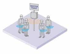
In the event of an emergency alarm personnel are required to go to designated areas, often called “Muster Points” and until recent times the method to account for all personnel has been implemented by signing in and out of plant areas using a register or “T Cards.”
Manual methods were enhanced by the use of swipe cards or non contact close proximity card readers using the first generation of RFID technology. These methods are just electronic versions of the “T Card” or “Register” system requiring personnel to manually sign in or out of plant areas or at the “Muster Point”.
These basic methods have a major disadvantage as they require the person to remember to sign or swipe in and out of plant areas and are time consuming to tally that all the personnel that have assembled at the different “Muster Points” equates to the total number of people on the entire plant.
Not having accounted for the correct amount of people poses a nightmare scenario, especially in the event of a real emergency where emergency crews are tasked with locating the missing personnel. In real life emergencies minutes can mean the difference between life and death.
It is a common fact that on a plant with several hundred people spread over large areas manual mustering can take up to an hour which is far from satisfactory, considering these statistics have been established under ideal conditions where staff are aware that there will be a practice of the emergency evacuation procedures.
RFID Technologies
To overcome the problem of remembering to sign or swipe in and out of plant and to speed up the whole Mustering process modern RFID technology can be utilised. There are essentially three type of RFID technology available;
Figure 1. Passive RFID Tags
Passive: This type of tag typically works on LF (Low Frequency) 125KHz, HF (High Frequency) 13.56MHz or UHF (Ultra High Frequency) 868MHz and has no internal battery power source but induces current from the RF field to power the tiny radio transmitter built into the Tag.
These tags only transmit their identity when being read (in the RF field of a Reader) and do not have any other functions as they are effectively a wireless barcode. A point to note is that there are some versions that allow writing to the tag as well.
The typical read range of a LF or HF tag is up to a maximum a few tens of centimetres depending on the antennas and RF power used. The new EPC Class 1 GEN2 standard UHF tags can have a read range of up to 6 metres. The advantages of these tags are that they require no maintenance and are low cost.
Assisted Passive: This type of tag still is still a proprietary technology in that no international standard exists at the moment, although there are companies that are working towards one.
The tag has a small coin cell type battery which is used to help power the transmitter and thus read ranges of up to 50 metres line of sight may be achieved although in practice many do not perform anywhere near this range.
The tag still has very limited intelligence and offers no other functionality other than transmitting it’s ID. The cost is of course more than passive devices and once the battery has expired the tag must be replaced as the batteries are not replaceable.
Active: This type of tag is available in many variants and standards and typical frequencies they operate on are 868 MHz, 2.4 GHz or 3 to 6 GHz.
The power source is a much more substantial battery, typically a Lithium Ion primary cell which means the tag can incorporate a powerful microprocessor to provide many other intelligent functions such as motion detection, temperature measurement and emergency call button features.
The extra power for the radio transmitter means that the tag can transmit data up to 200 metres line of sight to a receiver at predetermined intervals or in the case of certain tags like the Extronics iTAG100 they also contain a LF 125KHz receiver so that the tag can be triggered to transmit a beacon to confirm its presence when it is in the field of a suitable reader called an Exciter.
Figure 2. iTAG100 Active WiFi & LF RFID Tag
Figure 3. iCITE100 LF Exciter
The read range of the tag in this case is up to 6 metres from the Exciter. These tags have to have the batteries replaced at certain intervals determined by the number of transmissions they make and of course they cost more than the other variants due to the enhanced features.
Battery life for these types of tags us up to 4 years but can be much less when making very frequent transmissions.
100% Read Reliability is Critical in a Mustering System Application
When utilising an RFID technology for Mustering applications the most important characteristic is the read reliability. It makes no sense to deploy a system where the read reliability is not 100% due to the fact this will mean that a person will be reported missing when they are not.
Passive and assisted passive tags do not have the read reliability to be considered for an Automatic Mustering System. The reason the read reliability is not 100% is due to the fact that the available power to transmit the RF signal is not sufficient to penetrate the human body due to the fact that the average adult body contains more than 70% water which attenuates the signal.
This is a major problem considering the tag must be worn by a person. There are possible solutions to this such as fitting a tag to the wearers Personnel Protection Equipment such as a hard hat and then fitting readers in ceilings above the choke point.
This is not an optimum solution and is a work around and even with such an approach in practice they still do not have a high enough read reliability.
Active tags on the other hand have much more powerful radio transmitters that allow the tag transmission to pass through the human body and can be programmed to send more than one transmission when in the RF field of a reader thereby achieving the near 100% reliability that is required for an Automatic Mustering System.
Mustering Stations and Entry/Exit into Zones
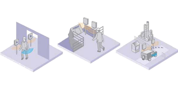
A Mustering Station usually consists of one or more readers at strategic locations around a plant where personnel go in the event of an emergency evacuation alarm.
Using two readers or antennas it is possible to determine the direction of movement of the person wearing the tag, so it is possible to count the numbers of people entering into certain areas or zones of the plant such as the site entrance and exit. Other benefits of this technology enable counting of people into life boats or across bridges etc on offshore platforms.
Figure 4. Muster Station using LF Exciter
Figure 5. Entrance and Exit Location Tracking using LF Exciters
Automatic Mustering Does not Solve all Problems
Once the Muster process is complete and it has been established that everyone is present then all is well. However it is a known fact that if an incident of some sort has occurred such as a fire or chemical spillage and someone is still unaccounted for the emergency services must try and find them.
So where does one search for the missing personnel after a muster procedure has identified they are missing?
Overcoming this problem is now a key objective for Health and Safety Managers in the Process Industries. The most obvious solution is to install large numbers of readers around the plant so that the last known location is determined by the last reader the person walked by.
This technique is often acceptable in mines where tunnels or sections of tunnels would be the likely location where a missing person/s could be found due to the fact they can only follow the tunnel.
On a process plant such as a refinery or chemical plant this method is not practical as there would have to be an uneconomical number of readers positioned across the site, as people can walk in any direction. The level of accuracy would also be poor and at best a zone or area of the plant could be determined.
The desire by plant operators to be able to track their work force and know their exact location to within a few metres accuracy is becoming more compelling due to increasing demand in legislation that is designed to protect the welfare of workers in industry.
Being able to pin point the location of a worker who has not made it to the “Muster Points” means emergency services can be deployed to the exact location and undertake a rescue in the fastest time possible. Using this technology minimises resources and limits the exposure of the rescue team to any dangers on site and increases the chances of a successful rescue.
Where are the Missing Persons?
Wireless technologies that have been in existence for the past decade are now well developed and mature enough to overcome the last hurdle in emergency evacuation procedures.
There are several Real Time Location Tracking technologies that can be applied based on one or more location principle, each with their own key benefits and disadvantages.
Be it proprietary hardware, will only work outdoors or indoors, accuracy may be affected by multi-path RF reflections or that the cost of the infrastructure is prohibitive. As is often the case, no one technology can resolve the problem in its entirety.
Real Time Location Principles
The basic principles used by most Real Time Location Systems (RTLS) are Received Signal Strength Indication (RSSI) and Time Difference of Arrival (TDOA).
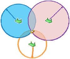
Received Signal Strength Indication is the strength of the signal from a transmitting device as measured by a receiver.
The RSSI value of a transmitter is measured by a receiver such as a WiFi Access Point and location is derived from the relationship of radio signal strength to distance. If the RSSI is measured by at least three receivers the position is calculated based upon the intersection of those distances from the receivers installed at known locations.
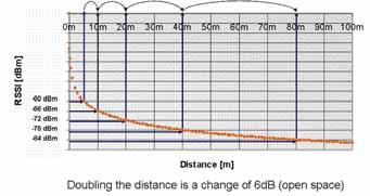
As the relationship is Non Linear the RSSI principle can only practically be used for shorter distances.
Figure 6. Location of tag using RSSI principle
The accuracy can also be affected by RF multipath, due to reflections from hard surfaces such as metallic structures.
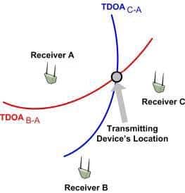
Another very common location principle is Time Difference Of Arrival (TDOA) which is the process of locating an object by accurately computing the time it takes for a transmitted radio signal (speed of light) to travel to a receiver at a known location.
The Time Of Arrival (TOA) of a transmitting devices signal is measured by at least three time synchronised receivers. The transmitting device’s position is determined by calculating the TDOA of the signal at these receivers and uses this information for triangulation.
Figure 7. Relationship of RSSI to distance
When a transmitting device sends a signal, it arrives at slightly different times at two spatially separated receivers. For given locations of the two receivers, a whole series of transmitter device locations would give the same measurement of TDOA.
Given two receiver locations and a known TDOA, the range of possible transmitting device locations creates a hyperbola. A receiver at a third location would provide a second TDOA measurement and therefore locate the device on a second hyperbola.
Assume an unknown transmitting device X and known receivers A, B and C. The TDOA between each pair of receivers is calculated as follows: TDOA(B-A) = |TB – TA| TDOA(C-A )= |TC – TA|
The hyperbolic plots representing all possible difference of distances of the transmitting device from each pair of receivers. The intersection of two or more hyperbolae defines the position.
The TDOA principle is much more tolerant to RF multipath problems that are experienced in the Process Industries due to the fact advanced algorithms in the location engine can be applied to this measurement principle.
Another principle that is worth mentioning is Angle of Arrival (AOA) whereby the location is determined by measuring the angle that a transmitted radio signal is measured at a receiver at a known location.
The method is not commonly used due to the fact that it does not really offer any tangible benefits over the TDOA and RSSI principles due to requiring special antennas and the overall hardware costs generally being higher.
Figure 8. Hyperbolic plots representing possible difference of distances
Real Time Location Technologies
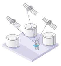
One location technology we are all familiar with in our everyday lives is GPS which in outdoor areas will provide location accuracy to sub 10 metres by receiving signals from at least 3 satellites and using Time Difference Of Arrival (TDOA) algorithms to calculate the position of the receiver.
This technology does not work indoors as the RF signal is not powerful enough to penetrate though buildings and needs a wireless network of some sort to update the location tracking software with the last location due to the fact the GPS satellites only transmit and have no receive mode.
Figure 9. Location using the Global Positioning System
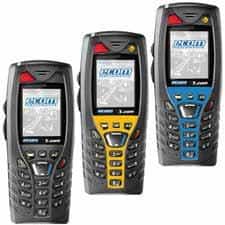
New products are now becoming available such as a mobile telephone with a GPS receiver, dead man sensor and emergency call button.
Figure 10. Ex Mobile Telephones with GPS
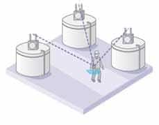
Another familiar technology is the WLAN or WiFi network that most of us have at home or in the office.
If there are a number of access points providing blanket coverage in cells across a site it is possible to use the Received Signal Strength Indication (RSSI) to calculate the position of the tag, again by using a triangulation calculation algorithm much like that used by GPS except based on signal strength.
This principle of location works indoors with an accuracy of sub 5 metres as well as outdoors but with much less accuracy.
The reason for this being the fact that the relationship between WiFi signal strength and distance becomes exponential after about 50 metres which means the cost of installing a high density matrix of access points would become prohibitive.
Such a high density matrix is much more than is needed for most mobile computing applications, where an access point every 100 to 150 metres will more often than not provide adequate outdoor connectivity and throughput.
Some vendors have also developed their own receiver that has a TDOA (Time Difference of Arrival) function as well and will work outdoors up to 200 metres with sub 5 metre accuracy.
The only downside with this is the proprietary infrastructure, which unlike a WiFi network cannot be used for any other purpose meaning the “Return On Investment” (ROI) takes much longer than a WiFi based location system.
Figure 11. Location using WiFi Networks
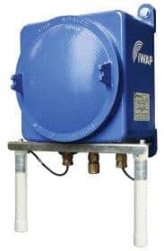
Figure 12. iWAP103 Access Point Enclosure System
Some companies are demanding location accuracy of sub 5 metres for use in a very dense metal environments such as a processing unit on a refinery where it is impossible to visually spot someone from more than a few metres away.
In a 100 x 50 x 50 metre process unit consisting of metal pipes, vessels, walkways and stairs the only technology that can provide a solution with this degree of accuracy is Ultra Wide Band (UWB).
This location technology (similar in principle to radar) can perform to less than 1 metre accuracy, even better is some cases. The other advantage of this technology is that it is possible to calculate location in 3D with suitably placed location receivers.
The method of location calculation is both TDOA and also AOA (Angle of Arrival) However the density of the receiver infrastructure required makes this technology prohibitive to use over a complete site.
Providing an economical solution to mustering is now possible and practical to implement but what solution can provide economical location and tracking of people across a complete facility?
It is hard to imagine industry investing huge sums of money to locate personnel down to sub 1 metre accuracy when there is no need and especially as a very large investment in infrastructure that would be required.
It is a common convention now that WiFi is a good investment for industry and can improve working practices, overall efficiency and safety. The Process Industries are now starting to install blanket WiFi coverage in their plants for data and voice applications.
Using the WiFi network as the primary means of Location Tracking makes sense as it has already been installed for other reasons so the ROI is greatly improved.
New tags are being developed that combine GPS and UWB technologies with WiFi and LFR provide an ultimate solution for plant wide location tracking.
Where the level of location accuracy is not adequate by using WiFi alone, such as in large open outdoor areas with a low density of installed Access Points, the GPS mode would be used.
In places where a sub 1 metre accuracy is required, such as in a processing unit where the mass of pipes, vessels and walkways make it necessary to have “pin point” location accuracy, UWB location receivers would be installed. The UWB transmitter in the Tag would then be used.
The most practical and cost effective approach to choosing an RTLS (Real Time Location System) is to adopt a granular approach to the location accuracy and to utilise the most appropriate location technology for the level of accuracy required for that particular area of plant which keeps the costs of the complete RTLS infrastructure to a minimum.
Figure 13. GPS, LFR & WiFi Tag Counting
Enhanced Safety Features
With active tags having a powerful processor it is possible to add advanced safety features to the location tracking functions offering a compelling solution to worker safety. A sensitive motion sensor is used to monitor for “man down” and will raise an alarm if not motion is detected for a defined period.
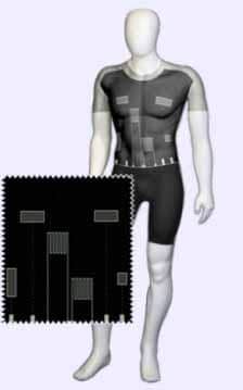
A local button on the Tag allows the worker to call for emergency assistance by raising an emergency call. Technology also exists such as the SmartLife® Technology wearable life signs monitor whereby the workers vital life signs such as ECG (Electro Cardiography) Respiratory Function, heart rate and body temperature are monitored continuously so that in the event of any abnormal measurements an alarm can be raised.
This new technology offers the possibility of the true “lone worker” whereby a “buddy” is not required as the lone workers safety is continuously monitored from a central location. The enhanced worker protection as well as dramatic cost savings offer a compelling argument for investment in such Automatic Mustering and Personnel Location systems.
Figure 14. Smartlife vest for monitoring vital life signs
Thorne & Derrick are Specialist Distributors of Hazardous Area & Explosion Proof Equipment with IECEx & ATEX Certifications to the onshore and offshore oil, gas, petrochemicals and process industries.
T&D’s online library of Drum & IBC Heating applications is now updated to include the following : Imidodisulfuryl Chloride heating using bespoke heating jackets for containers in a hazardous area location.
Visit Silicone Heaters for details of electric surface heating solutions – flexible silicone heaters can be applied to heat the most complex shapes, geometries, curves and pipes.
HeatING JACKET Type
Drum
IBC
Bespoke ✓
area Classification
Safe Area
Hazardous Area (Zone 1 & Zone 2) ✓ II 3 G EExe IIC T4
Medium Temperature Heating (21-50 degrees Celsius)
High Temperature Heating (50 degrees Celsius+) ✓
Other
Client required a ATEX heating jacket for a new product containing Imidodisulfuryl Chloride which required heating to 60ºC and maintaining at this temperature. A safe area jacket was designed and produced for R&D trials and once trials were complete, T&D were tasked with replicating the same product within an ATEX environment. Full design & consultation from R&D stage to finished product.
IBC Heating Jackets – T&D supply heating and insulating jackets for plastic or steel metal cage IBC’s for bulk liquid storage.
Bespoke Heating Jackets for chemical drums & ibcs
110 Volt
230 Volt ✓
Low Voltage
HEATING APPLICATION : DRUM, IBC, TANK OR VESSEL
25 Litres
50 Litres ✓
105 Litres
205 Litres
1000 Litres
Other
VESSEL MATERIAL
Steel ✓
Stainless Steel
Plastic
Cardboard
Other
HEAT UP TEMPERATURE
0-5 degrees Celsius
5-20 degrees Celsius
20-50 degrees Celsius
50-70 degrees Celsius ✓
70+ degrees Celsius
N/A (Frost Protection)
HEAT UP TIME REQUIREMENT
0-4 Hours
4-12 Hours
12-24 Hours
24-48 Hours ✓
N/A (Frost Protection)
Contact T&D for specification, support and sales of Electrical Heating Equipment for safe, industrial and hazardous area plant and equipment – we provide process temperature heating and frost protection (Winterisation) products for pipework, valves, IBC’s, drums and tanks, including hazardous area immersion heaters.
T&D – Largest UK Stockist of Heat Tracing Cables – UK & International Delivery
Invitation – network, engage, promote
Thorne & Derrick are inviting you to join LinkedIn’s fastest growing Discussion Group :Process & Hazardous Area Industries : Heat Tracing, Gas Detection, Fluid Control & Flow Measurement. News, projects, videos, promotions, whitepapers, jobs, webinars, press plus much more.
Press Release Date: 02.04.2020 uploaded by Chris Dodds (T&D Sales + Marketing Manager) World’s First Fully Certified ATEX Doors Thorne & Derrick International, the Experts in Equipment for Explosive Atmospheres, today announce the signing of a Commercial Distribution Agreement...
Press Release Date: 04.07.2019 uploaded by Chris Dodds (T&D Sales + Marketing Manager) Category: Stockist Distributor Agreement Announcement Thorne & Derrick International announce that they have signed a Preferred Distributor Agreement with Raytec, the world leading manufacturer of LED...