Declan Barry has an objective to make the industry safe by installing the appropriate explosion protection solutions to industry with full back up services. With 42 years of experience providing Explosion Hazard Services to the process industry, ATEX Explosion Hazards Ltd have a wide range of expertise within their group of companies.
This is the third in a series of eight articles, which aim to help you establish a simple basis of safety in your plant and dispel some of the myths associated with process and safety risk assessments.
Hazardous Area Classification
Hazardous Area Classification
The dangers of siting electrical apparatus in areas where explosive mixtures of gases and air could occur were first recognised in the mining industry early in the 20th Century. The chemical and petrochemical industries recognised that, unlike coalmining, the occurrence of flammable atmospheres was due to mechanical and process failures or deliberate situations created by man.
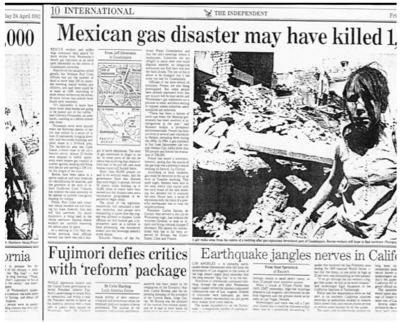
This newspaper article covers a widespread n-Hexane vapour explosion through a drainage system, although reporters referred to is as a ‘gas’ explosion.
Hazardous Area Classification | zones
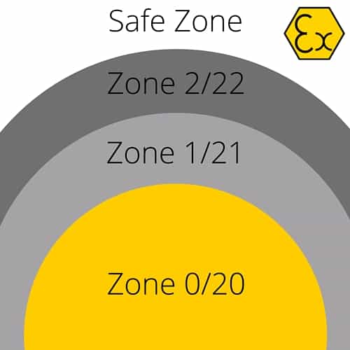
A fairly simple set of rules was developed dividing areas where flammable atmospheres could occur into 3 areas of risk, based upon frequency and persistence. This approach was taken up nationally and appeared in a British Standard Code in 1959. Today hazardous area classification (HAC) covering natural gas installations, solvent handling, oil pumping, etc. is a statutory requirement throughout EU Member States and under the Dangerous Substances & Explosive Atmosphere Regulations 2002 (in the UK), in particular. The zone definitions are as follows:
Zone 0
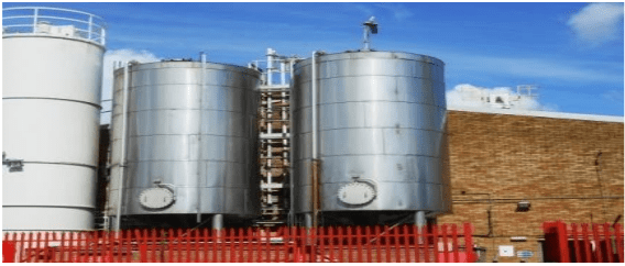
A place in which an explosive atmosphere (from gas, vapour, mist or spray) is present continuously or for long periods or frequently – e.g. solvent storage tank operating continuously above the ash point of the liquid, etc
Zone 1
A place in which an explosive atmosphere (from gas, vapour, mist or spray) is likely to occur in normal operation occasionally – e.g. sampling point where the liquid is above its ash point temperature, etc.
Zone 2
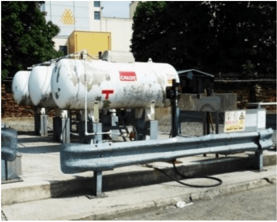
Zone 2, within hazardous area classification, is a place in which an explosive atmosphere (from gas, vapour, mist or spray) is not likely to occur in normal operation but, if it does occur, will persist for a short period only – e.g. leakage from gas pipework flanges, fittings, etc. Key parameters to be considered include liquid ash point, gas or vapour density, the leak or emission rate, the prevailing level of ventilation (natural or forced), pressure, temperature, LEL, height of release, etc. Oddly, historically, the HAC job was often given to electrical or instrument personnel when it was (and still is) a matter for process engineering!
Zone 20
A place in which an explosive atmosphere in the form of a cloud of combustible dust in air is present continuously or for long periods or frequently – e.g. inside cyclones, hoppers, containers, pipework, etc.
Zone 21
A place in which an explosive atmosphere in the form of a cloud of combustible dust in air is likely to occur in normal operation occasionally – e.g. vicinity of powder filling/discharge points, weigh stations, sampling points, etc. and where dust layers occur and are likely in normal operation to give rise to an explosive concentration.
Zone 22
A place in which an explosive atmosphere in the form of a cloud of combustible dust in air is not likely to occur in normal operation but, if it does occur, will persist for a short period only – e.g. outlets from cyclones, clean-side of dust filters, etc.
Historically, the following probability values have been used for guidance (with gases/vapours) and these are commonly applied to solids handling also.
Continuous Source
(> 1000 hrs. yr-1) yields a
Zone 0 / 20
Primary Source
(10 – 1000 hrs. yr-1)
yields a Zone 1 / 21
Secondary Source
(<10 hrs. yr-1) yields a
Zone 2 / 22
The relevant code of practice for Gas Installations with working pressures up to 2.0 bar.g is IGEM/UP/16 Comm. 1756.
“The design of natural gas installations on industrial and commercial premises with respect to hazardous area classification and preparation of risk assessments”. — UK Dangerous Substances & Explosive Atmosphere Regulations 2002.
Essentially, the use of effective and appropriate ventilation is the key to precluding hazardous areas in Boiler Houses, battery charging areas, etc. other than Zone 2 (NE) i.e. of negligible extent. Flammable vapour atmospheres will arise when liquids are handled or processed above their ash point temperature.
A 5K safety margin is normally applied for pure materials (solvents) when using ash point temperatures to dene whether or not flammable vapour-air mixtures will be formed. A larger 15K safety factor is recommended, however, for liquid/liquid or liquid/solid mixtures. For spillages, the open cup ash point (rather than close cup) value is more appropriate. The above discussion relates vapour pressure to temperature and in essence, assumes ‘saturated vapour-liquid equilibrium’. Care is needed with operations which produce high shear forces on a fluid, resulting in ‘non-equilibrium’ conditions e.g. high speed mixing, splash loading, etc.
Similarly, flammable atmospheres can arise through mist or spray formation (by mechanical means or condensation). Fine mists can form flammable mixtures well below (may be 200K or more) the ash point of the liquid. The potential hazard arises from leakage of fluids under pressure, from compressions joints, oil seals, etc. The use of flange-guards can eliminate the hazard, however.
Dust
In the case of dusts, most sources of release in normal operation should be small, and should be controlled at source, since the increasing concern to reduce occupational health risks from breathing in airborne material should have reduced the number of areas where dust is released regularly into the general atmosphere.
With regard to the extent of a hazardous area (Zone), this very much depends on how much dust is released and whether it would be released as a heap that settled quickly on the oor or as a large cloud. For instance, a sack that tore as someone picked it up might release (say) 5-10 kg, but most would settle very quickly. However, a Flexible Big-Bag (FIBC) where the tie became loose after lifting might release 500 kg (or more) at high level. Also, a pneumatic transfer line might release a very large amount as a cloud.
Unlike releases involving gases and vapours, there is no simple method available of calculating how far from the source a release of dust of a given quantity with a known pressure behind it will form a dense cloud.
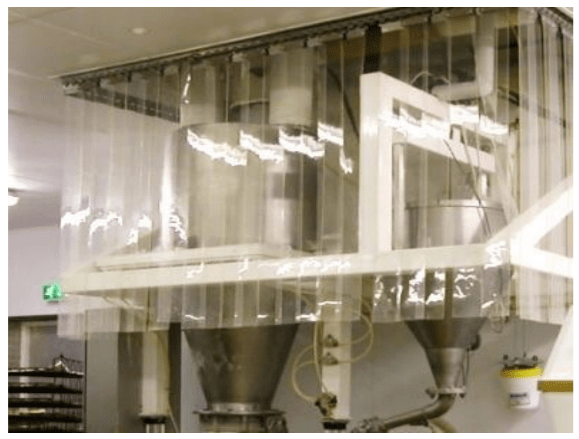
However, it is clear that if the release could produce a dense cloud (say larger than a couple of metres from the source), a means of minimising quantity of dust that could be released and its spread should be sought. Often, the provision of simple plastic or fabric curtains are considered to be helpful.
Predictable Hazardous Areas
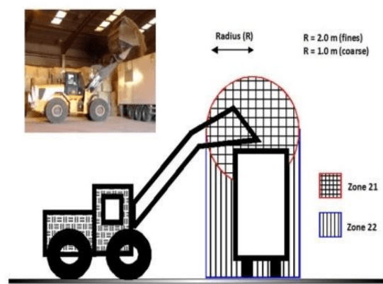
Equipment which is opened up for cleaning, maintenance, etc. may give rise to explosible dust clouds externally if material held-up on internal ledges, back-sides of doors, etc. is dislodged. To cover this, a ‘generic’ Zone 22 area of 1.0 m extent (to solid floor level) is often proposed. However, since the formation of such hazardous areas is predictable, it is not necessary to provide certified equipment within the hazardous area so formed if the work is done under a STRICT permit system i.e. a safeguard whereby uncertified (unsuitable) equipment within the vicinity has been de-energised and isolated. The hazardous area still remains, however.
Dust Extraction
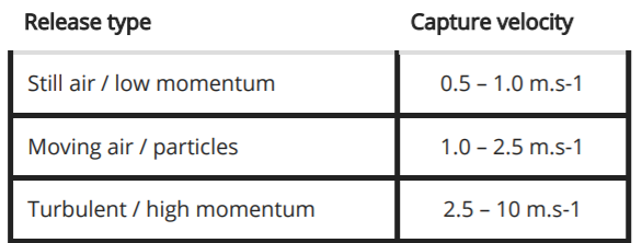
Dust extraction is important to limit fugitive emissions and it should be routinely monitored to ensure satisfactory performance. In addition, the level of ventilation should ensure that the dust-air concentration does not routinely exceed 25 % of the lower explosive limit LEL or minimum explosible concentration MEC). The ‘capture velocity’ is also important and this depends on the level of air movement in the region of interest.
Dusts, which are not removed by mechanical extraction ventilation, settle out, at a rate depending on properties such as particle size, into layers or accumulations and account has to be taken of the fact that dilute or small continuous sources of release (in time) may produce a potentially hazardous dust layer.
Principally, three risks are presented by dust layers:
Risk 1: A primary explosion within a building may raise dust layers into clouds, and cause secondary explosions more damaging than the primary event. Dust layers should always be controlled to reduce this risk.
Risk 2: Dust layers may be ignited by the heat flux from equipment on which the layer rests. The risk is of fire, rather than explosion, and this may be a slow process.
Risk 3: A dust layer may be raised into a cloud, ignite on a hot surface and cause an explosion. In practice, dust cloud ignition temperatures are often much higher than layer ignition temperatures. For example, Paper fines have a layer ignition temperature of 210 – 275 °C, but a cloud ignition temperature of > 450°C.
These risks depend on the properties of the dust and the thickness of layers, which is influenced by the nature of the housekeeping. The likelihood of a layer catching re should be controlled by the correct selection of equipment and effective housekeeping.
Signage
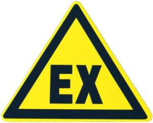
Arrangements must be made for the display of ‘EX’ signage in appropriate locations. Additional information (wording) can be incorporated to highlight the specific hazard i.e. Explosive Gas/Vapour/Mist Hazard or Explosible Dust Hazard
Potential Sources of Ignition
The next article in this series of eight is entitled: Potential Sources of Ignition.
The aim of these articles is to help you establish a simple basis of safety in your plant and dispel some of the myths associated with process and safety risk assessments.
LEADERS IN ATEX INNOVATION TO THE HAZARDOUS AREA INDUSTRIES
Thorne & Derrick are leaders in the development and distribution of Product Innovations that deliver significant improvements to clients plant, people and operational safety in the explosive atmosphere industries.
Your proactive problem solvers experienced in succession planning for the replacement of obsolete, non-conformant and legacy equipment in hazardous areas.
Your first-choice provider of innovative and competitive solutions to ensure ATEX & IECEx Compliance for Hazardous Area Electrical, HVAC & Process Instrumentation Equipment to UK and international projects.
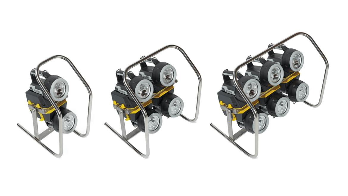
Wolf ATEX Zone 0 Flood Banks use portable handlamps to deliver a bright flood of light to hazardous work areas including those with potentially explosive atmospheres.
Wolf portable lighting with a flood bank can offer up to 2,100 lumens all in a self-contained and portable unit. The flood bank range is available in either 2, 4 or 6 handlamp bank configurations and the stands can be placed on level ground or mounted on a tripod (available separately) to elevate, direct and focus the light onto the desired working area.
What is Zone 0?
Zone 0 and Zone 20 classified hazardous areas are places in which an explosive atmosphere consisting of either a mixture of flammable substances in the form of gas, vapour or mist (Zone 0) or a cloud of combustible dust (Zone 20) is present in the air continuously or for long periods of time.
An explosive atmosphere is defined as a mixture of dangerous substances with air, under atmospheric conditions, in the form of gases, vapours, mist or dust in which, after ignition has occurred, an explosion could take place.
Models – Wolf XT-602, XT-604, XT-606 Hazardous Area Zones: 0, 1, 2, 20, 21 & 22
The ATEX Zone 0 Flood Bank, manufactured by Wolf, makes use of the excellent performance and reliability of the Wolflite XT Rechargeable Zone 0 Handlamps to collectively deliver a flood of illumination, of up to 2,100 lumens, to a Zone 0 hazardous task area.
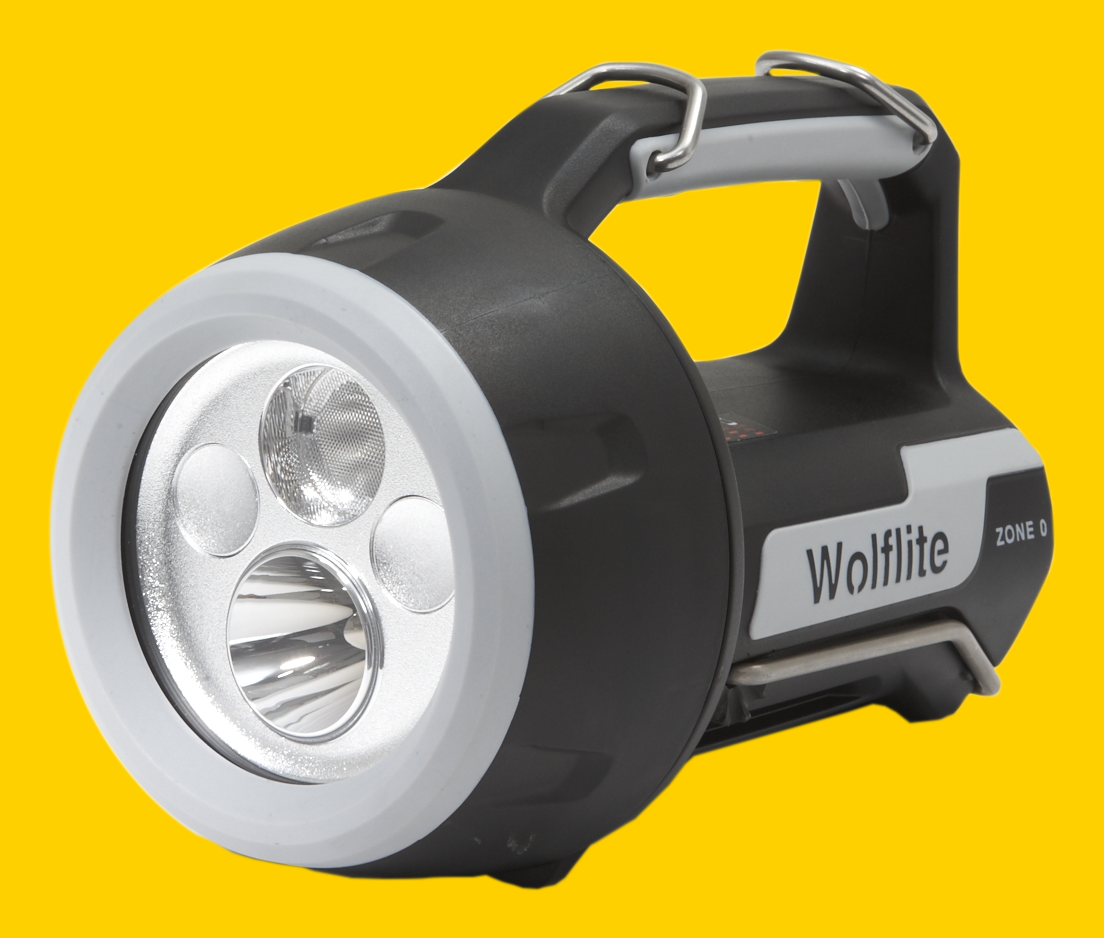
Wolf flood bank stands integrate the Wolflite XT Rechargeable Zone 0 Handlamps (Wolf XT-75) which are CE marked to the ATEX Directive and IECEx Certified, for safe use in Zone 0 potentially explosive gas atmospheres, where a T4 temperature class permits.
The XT-75 Zone 0 Handlamps’ bespoke optics coupled with the highest performance ‘fitted for life’ LED light sources deliver an outstanding light output, of over 350lms each, from the high intensity spot beam, switchable to a wide-angle flood. The battery duration at high output is 7.5 hours and 15 hours in powersave mode and is monitored with a state of battery charge indicator.
Made of stainless steel, each stand incorporates handlamp holders with ‘snap-in/snatch-out’ function for quick release but secure retention and allows the bank of handlamps to be manually tilted and locked in position.
The handles makes the banks easily transportable for maintenance tasks and individual handlamps are easily swapped, even with gloved hands, allowing for straightforward function selection and use.
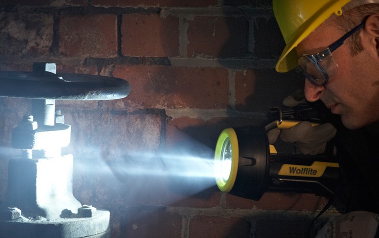
Handlamps can be removed from the stand within the Zone 0 hazardous area to be used for close up inspection work or in awkward to reach places, plus the Flood Bank can act as an emergency backup light source, independent of lead powered lighting.
The Wolflite XT Rechargeable LED Handlamp range is available in a number of different models in order to optimise performance in specific applications.
Bespoke optics and the high performing ‘fitted for life’ LED light sources deliver outstanding light output from the high intensity spot beam; making them ideal for tasks requiring a higher light intensity. A wide-angle flood option is also available, for tasks requiring a less extensive light.
Additional coloured LED signals can also be added. All products in the XT range feature easy, single-handed changeover even with gloved hands to allow for straightforward function selection and use.
Battery duration varies by model, from 4 hours of high output light (XT-50) to 11 hours (XT-90); by selecting the ‘powersave’ option, the duration can be doubled. The state of battery charge is indicated with a bar of bright red LEDs, which go out as battery charge diminishes and the beam flashes off repeatedly when recharging is required.
The latest lithium-ion battery technology improves reliability and also eliminates the ‘memory’ affect and the ‘quick’ charger base fully recharges the Handlamp in a minimum of 2 hours, dependent on model, and is configured as a holder with ‘snap-in/snatch-out’ function, for quick release but secure retention. Emergency illumination function illuminates Handlamp if power to the charger fails.
Wolf handlamps have a compact, lightweight body which has proven impact resistance even at sub zero temperatures; enhanced by rubber armoured lens ring, and handle/sides give improved grip and shock protection. The lens is resistant to scratches and chemical attack; the enclosure is electrostatic non-hazardous and certified to IP67.
➡ For further information, technical specifications and hazardous area ATEX certificates, please see the Wolf Handheld Leadlamps product sections below. Visit portable and temporary lighting for more information about the full range of Wolf Lighting products.
Portable & Temporary Hazardous Area Lighting
When clear vision and brilliant LED light is required in hazardous area locations or confined spaces with potentially explosive atmospheres, Wolf Safety lights provide bold, bright and unfailing portable and temporary lighting. Since 1912, Wolf has been trusted to light the world’s most hazardous and hostile environments – with ATEX & IECEX certified portable lights to provide safe lighting in explosive atmospheres.
leaders in ATEX Innovation To The Hazardous Area Industries
Thorne & Derrick are leaders in the development and distribution of Product Innovations that deliver significant improvements to clients plant, people and operational safety in the explosive atmosphere industries.
Your proactive problem solvers experienced in succession planning for the replacement of obsolete, non-conformant and legacy equipment in hazardous areas.
Your first-choice provider of innovative and competitive solutions to ensure ATEX & IECEx Compliance for Hazardous Area Electrical, HVAC & Process Instrumentation Equipmentto UK and international projects.
Follow our Showcase Page on LinkedIn to receive hazardous area product innovations, industry news, whitepapers, videos, technical tips and training webinars for professionals involved in the explosive atmosphere industries.
A Series of Articles to educate and inform those involved in the Hazardous Area & Explosive Atmosphere industries.
This Article is number 2 of 8 in the ATEX Safety & Explosive Atmospheres series.
Declan Barry has an objective to make the industry safe by installing the appropriate explosion protection solutions to industry with full back up services. With 42 years of experience providing Explosion Hazard Services to the process industry, ATEX Explosion Hazards Ltd have a wide range of expertise within their group of companies.
This is the second in a series of eight articles, which aim to help you establish a simple basis of safety in your plant and dispel some of the myths associated with process and safety risk assessments.
materiaL Hazards
This article focuses on Characterising Material Hazards
Industries producing and/or handling materials, which may form hazardous (flammable) atmospheres, must comply with the ATEX Directives.
In the UK, this requires compliance with the Dangerous Substances & Explosive Atmospheres Regulations (DSEAR). Similar NFPA Codes apply In the USA.
You cannot define the necessary systematic approach to protecting people and plant, without a knowledge of the potential material hazards in your work place: are flammable atmospheres present within your plant or processing areas?
The first step is to check your suppliers’ MSDS’s, your own records and the open literature for relevant test data.
Gestis is an EU funded database of combustion and explosion characteristics of more than 6000 dust samples from virtually all sectors of industry to help establish a basis of safety for the safe handling of combustible dusts. Gestis data is generic and may be indicative only e.g. it may not cover specific formulations or compounds, in which case, testing will be required.
Where a dangerous substance is or is liable to be present at the workplace, the employer shall make a suitable and sufficient assessment of the risks to his employees which arise from that substance. — Gestis
MAterial HAzards
How do you know a material is dangerous unless you test it?
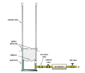
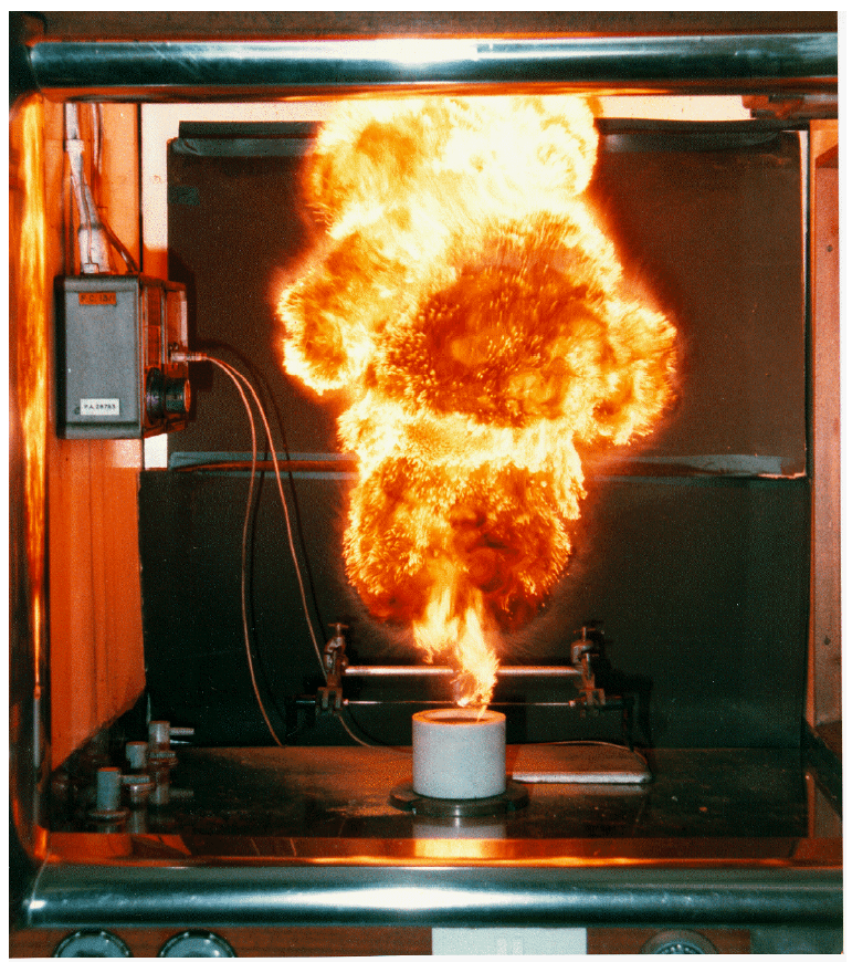
Group A/B (Vertical Tube) Test: Essentially, the dust under test is dispersed in air at ambient temperatures, past a source of ignition and observations of flame propagation made by the operative. The photograph shows the test apparatus with the tube removed for clarity. This classification test is a qualitative assessment of the ability of a dust to take part in an explosion:
Group A is a dust, which is able to ignite and propagate flame.
Group B is a dust, which does not propagate flame
characterising material hazards
As in all explosion testing, the sample selected must be representative of the material from the plant at risk, typically the finest and driest material found.
Further testing is required for Group B samples if handled at elevated temperatures >110 degree C. Although this test may be superseded by the 20-litre sphere, it does give a very good visual feel for how the dust reacts to an ignition source at ambient temperature.
Once you have established that the dust is Group A Explosible, the next step is to examine the specific ignition and explosion parameters.
MAterial hazards | Dust Concentration
Lower Explosion Level (LEL for gases and vapours) or Minimum Explosible Concentration (MEC for powders) is typically of the order 45g/m3 and 30-60 g/m3 respectively. The Upper Explosion Level (UEL) is not as clearly defined for powders, but usually is >1000g/m3.
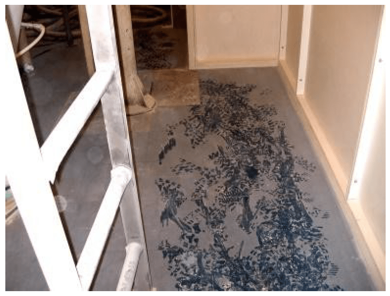
Do you leave footprints where you walk?
If so, there may be a secondary explosion risk. Consider a room 10 m x 10 m x 5 m high. What thickness of deposits will form a flammable (explosible) atmosphere throughout the room? A thickness of just 1 mm can equate to 75 kg of powder (depending on density) and if this was dispersed in the 500 m3 volume, the resulting concentration is 75,000 / 500 = 150 g/m3 i.e. well within the flammable range. How might this be dispersed, you may ask? During cleaning operations using air-jetting!
PArticle Size
This is a very important factor as particles greater than 500micron are unlikely to cause dust explosion hazards. This is why most tests are carried out below 100 micron or the standardised 63 micron. This may be a futile action due to attrition, as transportation of granular material may create a fines fraction.
MAterial hazards | Moisture Effects
Explosion violence falls at higher moisture contents:
0-5% has little effect
5-10% decreases sensitivity
>25% particles unlikely to stay in suspension
Minimum ignition temperature: MIT Cloud
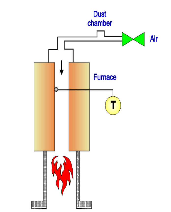
The Minimum Ignition Temperature of a dust suspension is the lowest temperature at which it will ignite spontaneously and propagate flame. This MIT value is particularly relevant to problems involving relatively large heated areas of plant e.g. surfaces of dryers, mills, electrical equipment, etc.
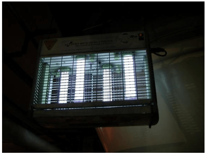
For example, you need to ensure that any escape of dust (as a cloud) does not spontaneously ignite on nearby heated surfaces e.g. electrical motors, insect-o-cuters, etc.
Ancillary equipment such as this is often ‘missed’ (overlooked) when shutting down plant for cleaning and maintenance purposes.
Minimum ignition temperature
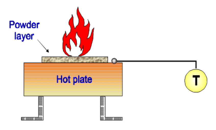
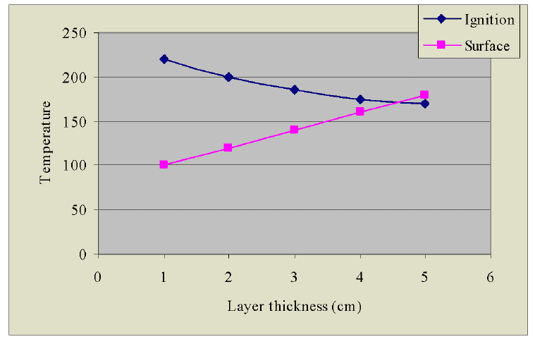
MIT (LIT) 5 mm Layer
The test determines the minimum temperature of a prescribed hot surface, which will result in the decomposition and/or ignition of a layer of powder of specified thickness. The test is particularly relevant to industrial equipment with hot surfaces, on which dust deposits may form. For example, you need to ensure that any escape of dust (which forms a layer) does not result in smouldering. Equipment must be kept clean with surface layers not exceeding 5 mm. Thicker layers will invalidate the T class rating of equipment and may cause ignition.
Minimum ignition Energy: The Dust cloud
Minimum Ignition Energy of a dust suspension is the lowest energy at which ignition and flame propagation away from the spark kernel occurs – the value being particularly relevant to identifying potential electrostatic ignition hazards. In principle, the test is similar to the Group A/B Test. Two circuits are employed – capacitive (for electrostatic ignition) and inductive (for friction spark ignition). Essentially, the difference between them lies in the duration of the spark i.e. increasing inductance will lengthen the duration of the discharge making it more incendive. Consequently, the MIE value with this circuit will be lower than that with a capacitated circuit e.g. 10 mJ compared to 30 mJ. Typically, MIEcap values range from 3 – 1000 mJ for dusts and 0.017 – 0.4 mJ for gases and vapours.
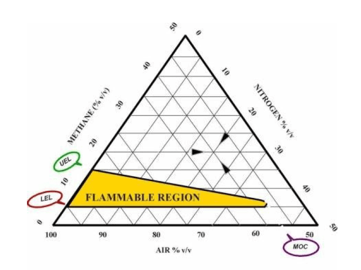
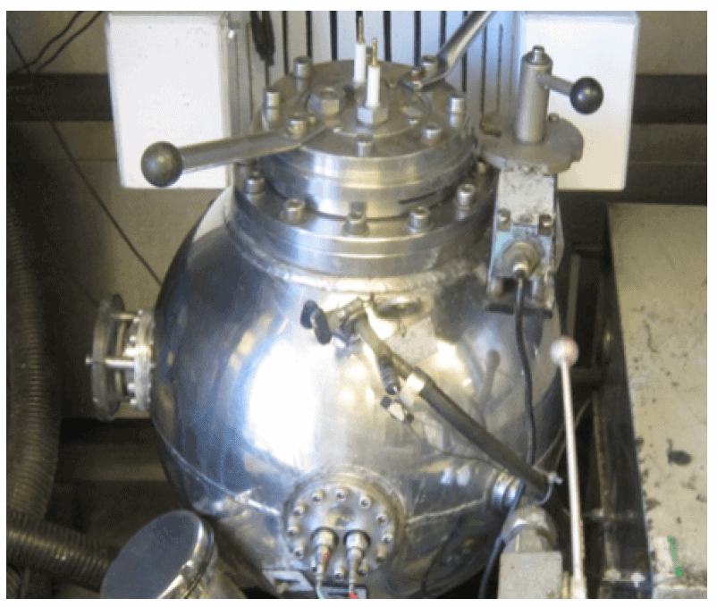
Essentially, a flammable atmosphere (be it gas, vapour or airborne dust) cannot exist below this level of depleted oxygen. The data is needed when basing safety on the use of inert gas, in certain milling or solvent handling operations, for example. The test is conducted in a 20 Litre Explosion Sphere. Typical MOC values lie in the range 8 – 15 % v/v (for powders) and 5 – 10 % v/v for gases and vapours. It is important to note that the MOC value depends on the type of material and the type of inert gas.
The schematic shows the flammable envelope for Methane.
Explosion Characteristics: Kst & Pmax
Although the methods above are relevant for prevention of flame and explosions, to confirm the quantitative assessment of a design for explosion protection you will need to conduct an actual controlled dust explosion in either the 20 litre or 1m3 test apparatus.
The dust sample is homogenously dispersed via deflector plates (typically) and ignited by a 10kJ source.
The development of the explosion pressure with time is monitored and the maximum peak pressure Pmax and maximum rate of pressure rise is obtained after a testing over a range of dust concentrations.
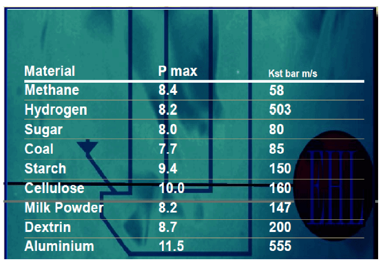
The peak value of the maximum rate of pressure rise (dp/dt) max is used to calculate a dust specific explosibility characteristic called Kst or Kmax = dp/dt max. V1/3
As shown, dust explosion pressures can reach the same as gases/vapours and some metal dusts can be as dangerous as Hydrogen.
Thermal Instability Testing
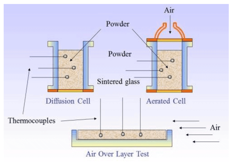
The Diffusion Cell, Aerated Cell and Layer Tests are used to assess the thermal stability of a material in bulk or layer form e.g. inside Dryers, etc. The cells are located in fan assisted ovens which can be run isothermally or in ramped mode. In addition, large scale basket tests may be required to assess the effect of scale.
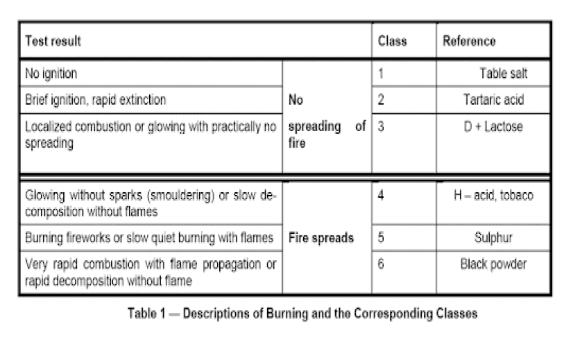
A separate Combustibility Test (comprising a train of powder ≈ 200mm long, ≈ 30mm wide and ≈ 20mm high) is used to assess the type and rate of flame/smoulder propagation along a layer of material e.g. inside ductwork, etc. It can also be used as an indicator of UN. Div. 4.1 ‘Flammable Solid’ materials for transport purposes.
The next article in this series of eight is entitled: Hazardous Area Classification. The aim of these articles is to help you establish a simple basis of safety in your plant and dispel some of the myths associated with process and safety risk assessments.
LEADERS IN ATEX INNOVATION TO THE HAZARDOUS AREA INDUSTRIES
Thorne & Derrick are leaders in the development and distribution of Product Innovations that deliver significant improvements to clients plant, people and operational safety in the explosive atmosphere industries.
Your proactive problem solvers experienced in succession planning for the replacement of obsolete, non-conformant and legacy equipment in hazardous areas.
Your first-choice provider of innovative and competitive solutions to ensure ATEX & IECEx Compliance for Hazardous Area Electrical, HVAC & Process Instrumentation Equipment to UK and international projects.
The ATEXInspect app can be used on any device with a browser and internet connection.
There is no need to install any software, just login and access your secure data from anywhere you need.
It will carry out inspections and automatically raise faults straight from your inspection. These faults can then easily have work orders assigned to them, completing the cycle.
Use ATEXInspect to manage other inspections such as emergency ATEX lighting and fixed wire inspections.
Allowing all related documents, drawings and certification to be accessed from one device while on site or in the office. The software can be accessed from multiple locations allowing collaboration between your sites and offices.
Why ATEX Inspect?
Team Collaboration – ATEXInspect allows remote collaboration. The originator may be on one site (or continent) and the checker or approver on another.
Element & Tag Database – The element database and Tag management application work together to manage your assets and allow you to reuse your elements throughout ATEXInspect.
Competence is now Mandatory – ATEX Inspect only allows personnel with appropriate competence levels to check and/or approve records.
Automatic QA Version Control– All critical records are traceable to originator/checker/approver with automatic ‘revving’.
Location Management– Manage your records using a hierarchy. Site – Plant – Area.
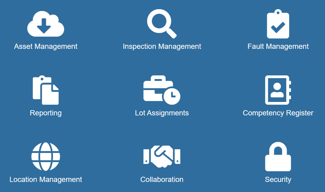
ATEX Inspect Features
Fault Management System
ATEXInspect has an innovative fault management system that gives live and updated information in real time. It enables the user to create your site standard fault codes, that can be assigned when hazardous area equipment is inspected.
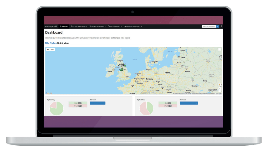
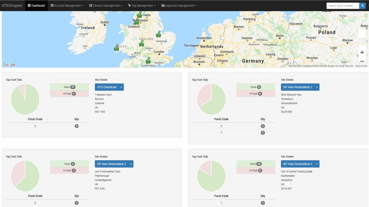
Using the ATEXInspect dashboard you can quickly identify how many of your tags are in fault, which are then categorised into the resolution of a fault, your operator can easily access the related tag and close out the fault.
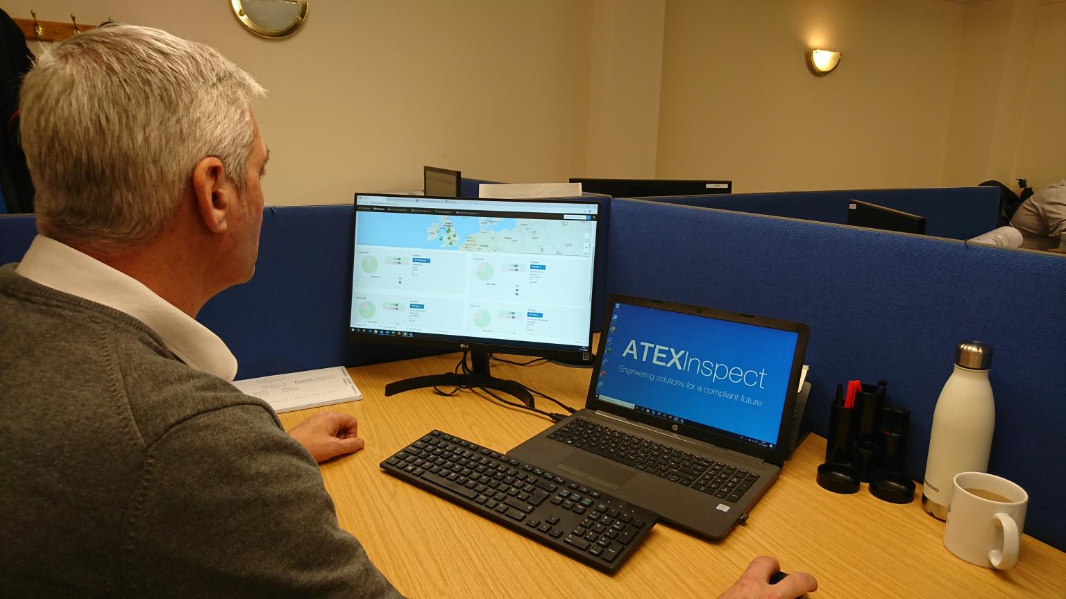
Site manager reviewing inspections and faults from the office
Reporting In Hazardous Area & Explosive Atmospheres
Included in ATEXInspect, the sophisticated reporting system allows the user to produce comprehensive reports based on your inspections.
These reports can be exported at site level or can be filtered down to a specific tag. They are available in both PDF or Excel formats, to support the needs of individual businesses.
Report Types
Site fault reports
Plant fault reports
Area fault reports
Inspection reports
Emergency lighting reports
Fixed wire reports
Data available immediately and accessible using any device with an internet connection
Hazardous Area Inspections
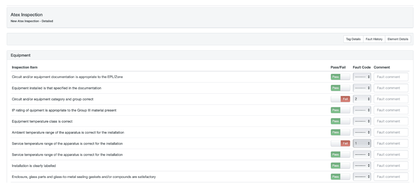
ATEXInspect offers three different types of inspections: ATEX Inspection, Fixed Wire Inspections & Emergency Lighting Inspections. All three are integrated into our fault management system. ATEX Inspect makes ATEX inspection effortless, by conveniently providing all information required to carry out inspections.
Who can inspect assets in a Hazardous Area?
IEC 60079-17:2013 states that inspectors must be able to demonstrate competency. ATEXInspect is a partner of HTS Group who have competent engineers with experience providing ATEX inspection services for a wide range of clients within the UK.
How can you prove the competency of staff performing inspections on your assets?
Certifications such as CompEx that prove competency can be uploaded to each user’s profile, each user has permissions that can be controlled via the competency register. Only competent staff have permission to check and approve records.
How is data on ATEXInspect secured?
Any data uploaded to ATEXInspect is stored using secure cloud servers. This allows data to be managed in alignment with security best practices and meet a variety of IT security standards. All communications between the user and the server are carried out over an encrypted connection (HTTPS). The data is backed up using a snapshot system allowing data to be recovered from previous dates.
Cloud based software for the management of equipment installed in potentially explosive atmospheres (ATEX). It will carry out inspections and automatically raise faults straight from your inspection. These faults can then easily have work orders assigned to them, completing the cycle | Contact us
Talk to us today about how we can improve operational safety, energy efficiency and optimise productivity in your hazardous areas.
We are your proactive problem solvers experienced in succession planning for the replacement of obsolete, non-conformant and legacy equipment in hazardous areas.
Your first-choice provider of innovative and competitive solutions to ensure ATEX & IECEx Compliancefor your UK and international projects.
Since 1985, T&D have established a solid reputation based onService, Integrity and Trust.
From our distribution locations with 50,000+ sq feet warehouse capacity and a £2.5 million stock, we can supply many products by next day delivery – our key sectors are the process, pharmaceutical, chemical, utility, food/beverage, renewable and oil/gas industries.
Author: James Astley PH Europe (UN Approved IBC & ISOtank Services | Promoting Safe Handling for Hazardous Goods
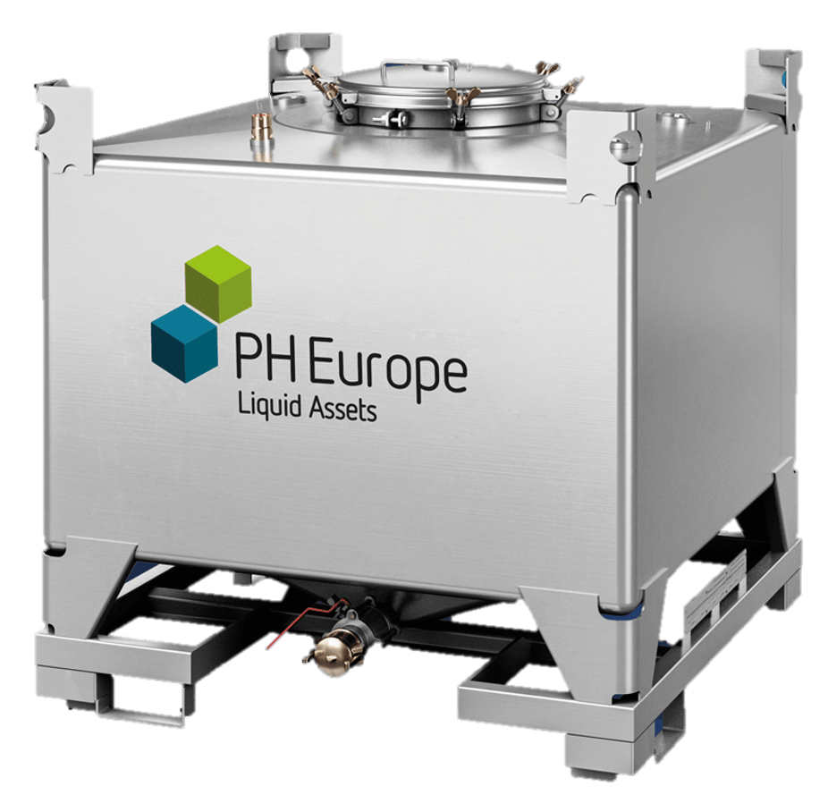
‘Intermediate Bulk Container’ (IBC) | PH Europe operate a large stainless steel IBC rental fleet and sales operation in the UK.
IBC
Intermediate Bulk Container
An ‘Intermediate Bulk Container’ (IBC) is a container used for transport and storage of fluids and bulk materials. IBCs have become widely used in the solvents industry as they can transport and store a larger volume of material than cylindrically shaped containers in the same surface area. As the number of containers can be reduced with the use of IBCs, this, in turn, reduces manual handling, and they are also more resistant to weathering.
Many solvents in use by industry are identified under UN Class 3 as being flammable, highly flammable or extremely flammable. Solvents can also be split into three categories; conductive, semi-conductive or non-conductive.
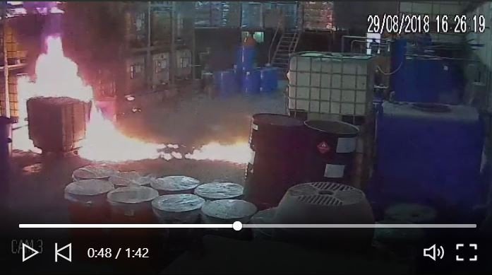
Not all solvents can be used safely with every type of IBC and so it is important to take care when selecting the right IBC to use with a particular solvent. IBCs have also been involved in some recent incidents, such as stacks collapsing, the ignition of contents due to static electricity and leakage leading to serious fires and risk to the environment.
It is important to take care when selecting the right IBC to use with a particular solvent
The Solvents Industry Association has compiled an overview, Guidance Note 51, (https://www.solvents.org.uk/sia-guidance-notes/) regarding the selection and use of IBCs to increase awareness among solvent users and to promote best practice in the solvent supply chain. This guidance should not be used in isolation and reference should be made to other Standards and Codes of Practice. In devising its methodology for the safe selection of IBCs, the SIA has sourced the classification of solvents into conductive / semi-conductive / non-conductive from existing Codes of Practice, but as their recommendations concerning the selection of IBCs for low-flash solvents are not universally agreed, the SIA has based its recommendations on the experience of the Solvents Industry in the UK environment.
Some solvents and pure hydrocarbons have low conductivity and therefore, present a significantly greater static risk than others as there can be a build-up of static charge which can spark a fire or an explosion.
To eliminate this hazard, the operator can either use a metal IBC (examples at www.pheurope.com) or an electrostatic protected composite IBC with a suitable specification, in combination with a suitable earthing system when filling or emptying, subject to the product’s flashpoint.
The tables below indicate the recommended IBC types to be used with low conductivity and low flash-point solvents
IBC Type (if compatible)
Flash Point of Solvent
<0ºC
0ºC to 60ºC
>60ºC
Unprotected Composite
No for N, S, C
No for N, S, C
Yes for N, S, C
Electrostatic Protected Composite
No for N, S
Yes for C
Electrostatic Protected Composite With Conductive Plastic Bottle & Permeation Barrier
Steel
Yes for N, S, C
Yes for N, S, C
Key: N = Non-conductive, S = Semi-conductive, C = Conductive solvents
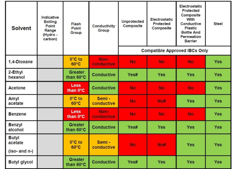
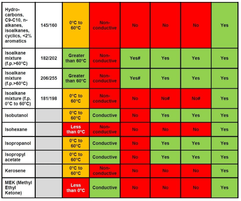
Based on the criteria in the SIA Guidance Note 51, example solvents have been tabulated against their recommended IBC types according to flash point and conductivity group.
Table 3: Recommended IBC Type Selection According to Solvent, Flash Point & Conductivity Group
(Editors note: From the above extract, stainless steel IBCs have been recommended for all except three solvents listed)
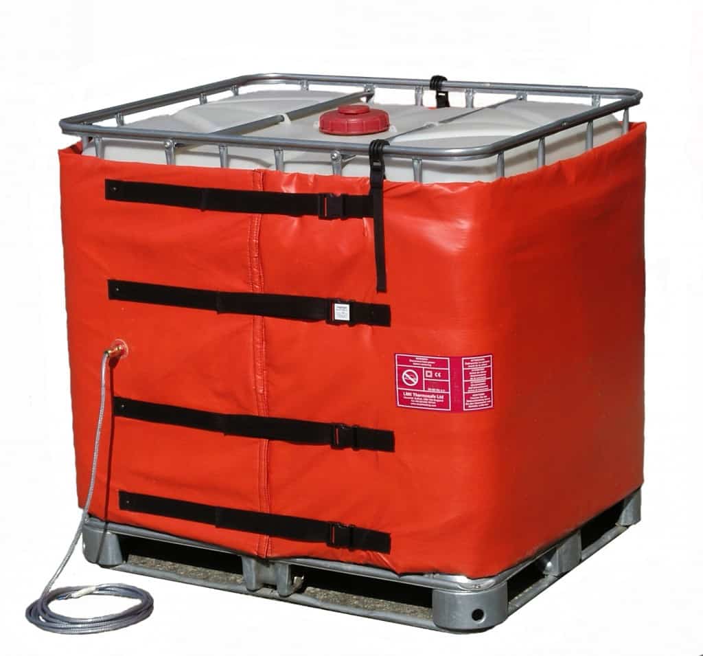
IBC Heaters | Insulated Heating Jackets For IBC Containers | Thorne & Derrick International are the UK’s Specialist Distributor of Drum & IBC Heating Equipment to diverse industries including process, food and beverage, confectionery, manufacturing, chemicals, pharmaceutical and utilities.
Talk to us today about how we can improve operational safety, energy efficiency and optimise productivity in your hazardous areas.
We are your proactive problem solvers experienced in succession planning for the replacement of obsolete, non-conformant and legacy equipment in hazardous areas.
Your first-choice provider of innovative and competitive solutions to ensure ATEX & IECEx Compliancefor your UK and international projects.
Since 1985, T&D have established a solid reputation based onService, Integrity and Trust.
From our distribution locations with 50,000+ sq feet warehouse capacity and a £2.5 million stock, we can supply many products by next day delivery – our key sectors are the process, pharmaceutical, chemical, utility, food/beverage, renewable and oil/gas industries.
Press Release Date: 02.04.2020 uploaded by Chris Dodds (T&D Sales + Marketing Manager) World’s First Fully Certified ATEX Doors Thorne & Derrick International, the Experts in Equipment for Explosive Atmospheres, today announce the signing of a Commercial Distribution Agreement...
Press Release Date: 04.07.2019 uploaded by Chris Dodds (T&D Sales + Marketing Manager) Category: Stockist Distributor Agreement Announcement Thorne & Derrick International announce that they have signed a Preferred Distributor Agreement with Raytec, the world leading manufacturer of LED...













 appropriate explosion protection solutions to industry with full back up services. With 42 years of experience providing Explosion Hazard Services to the process industry, ATEX Explosion Hazards Ltd have a wide range of expertise within their group of companies.