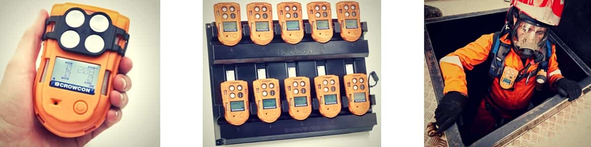
Crowcon T4, Portable Gas Detection In Confined Spaces.
The Crowcon T4 is the latest addition to the range of Crowcon portable gas detectors and provides protection in confined spaces against the four most common gas hazards. These hazards being carbon monoxide, hydrogen sulphide, flammable gases and oxygen depletion.
Key Facts And Features Of The Crowcon T4 Gas Detector
The many advanced features of the Crowcon T4 include rugged, IP65- and IP67-rated housing offering enhanced reliability in harsh environments, 24 hour safety, long battery life, TWA resume feature and an invertible screen.
All of the above features contribute to a low total cost of ownership and make the T4 portable gas detector the ideal choice for providing protection against hazardous gases.
The positive safety traffic light function gives the user constant assurance that the unit is compliant and operating correctly. This is done by a visual green LED light being illuminated when working correctly and flashing red when the unit needs attention.
Other key features include:
Easy one button operation
Clip on filter plates
Multi gas detection
Crowcon T4
The Crowcon T4 offers users a compact, portable and easy to use solution to gas detection problems and the one button function means the detector can be used when wearing gloves.
These features make the T4 perfect for applications in industries including oil and gas, petrochemical, wastewater and processing plants.
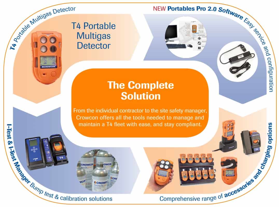
The quick view function of the Crowcon T4 enables the configuration details to be easily and quickly viewed even if the device is not powered by quickly pressing the operator button. The device will then emit an audible blip followed by the LED’s to the right of the display flashing red.
Bump testing of portable gas detectors is a vital, regular test that ensures the device is performing as intended. The OSHA defines a bump test as “a qualitative function check in which a challenge gas is passed over the sensor(s) at a concentration and exposure time sufficient to activate all alarm settings.”
It is recommended to bump test your portable gas detector daily before each use.
Crowcon T4 Gas Detector The Complete Solution
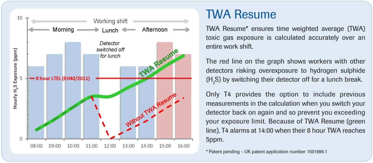
Crowcon T4 TWA Resume
When operating most portable gas detectors are operated and turned off, the technology will naturally assume that is the end of the shift. When turned back on the data is reset and ignore all previous measurements.
The TWA resume feature from Crowcon takes an average reading of the gas detectors exposure to gases over an eight hour period and ensures time weighted average (TWA) over an entire work shift.
Crowcon T4 TWA Resume Feature
Invertible Screen And Positive Safety Indicator
The Crowcon T4 features an invertible screen along with a positive safety indicator which is a simple ‘traffic light’ indicator. This can provide visual assurance of operational and compliance status for both users and supervisors.
The green light indicator means the detector is working safely and the red light indicator means the detector requires attention before use.
The backlit display provides a large, clear display and the option to invert the screen 180° for a clear view when worn upside down. The Crowcon T4 offers enhanced protection, complies to safety standards and is an extremely cost effective unit that is easy to adopt and maintain.
The features and functionalities of the T4 gas detector provide extraordinary value and is designed for use in industries such as oil and gas, water and wastewater, utilities and steel production plants.
Follow our Showcase Page on LinkedIn to receive hazardous area product innovations, industry news, whitepapers, videos, technical tips and training webinars for professionals involved in the explosive atmosphere industries.
ATEX Heaters – Mobile & Portable Hazardous Area Zone 1 & Zone 2 Heating
By Chris Dodds : estimated reading time 6 minutes
Safe. Reliable. Dependable.
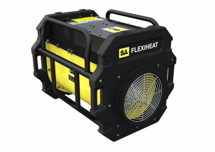
Portable Heating for hazardous area locations
T&D International are Specialist Distributors of Hazardous Area Electrical Heating Equipment – we distribute Flameproof, Explosion Proof and Intrinsically Safe equipment for Zone 1, 2, 21 and 22 hazardous area heating.
T&D are UK Approved Distributors for leading manufacturers of electric heating equipment for hazardous areas, including EXHEAT, Chromalox and Thermon.
T&D service the global oil, gas and petrochemical industries with heat tracing and electrical process heating equipment – the demand for portable hazardous area heaters includes offshore vessels such as drill ships, jack-up vessels, semi-submersible vessels, offshore barges and floating platforms.
Hazardous Area Heating
NEW : Portable ATEX Heaters
The application of reliable heat is often the only way to repair, remove or install equipment essential to offshore operations. Unfortunately, conventional heating methods (such as gas-fired open flames) and offshore atmospheres are potentially explosive bed-fellows. Sounds exciting in theory but is extremely dangerous in practice.
Hazardous area heaters must foremost be safe to use – certified according to the location, gas group, temperature rating and prevailing potentially explosive atmosphere. Know the Zone and match the certification of portable ATEX heaters for safe provision of heat without any hidden dangers.
For expert technical support in Hazardous Area Heating, Process & Instrumentation equipment selection, please contact T&D.
Additionally, offshore environments present hard-to-reach work sites. The equipment used to generate, apply and control heating must be rugged enough to withstand severe conditions, yet lightweight enough to be easily and cost-effectively transported.
Hazardous area heaters should be compact, powerful, user-friendly and portable.
Typical Temperature Rise Approx 20°C Above Ambient
Supply Voltage 400V (+/-10%) 3 Ph 50/60 Hz
Ingress Protection IP65
Typical Temperature Rise – Approx. 20°C Above Ambient
Portable ATEX Heaters are tough, compact, powerful, user friendly and easily moveable around jobsite.
Versatile : ATEX Heaters are suitable for multiple site configurations
Video : ATEX Heaters For Hazardous Areas
Portable Hazardous Area Heating
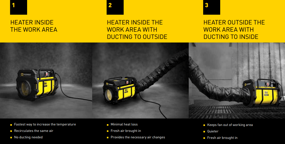
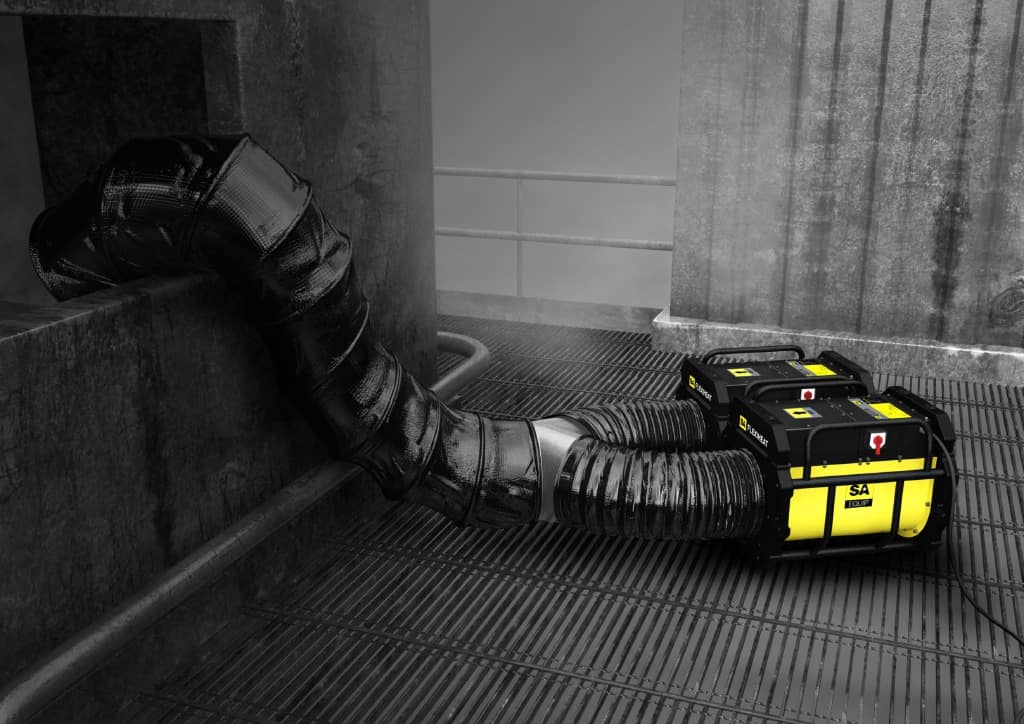
ATEX heaters can be configured to provide rapid heat-up with less ducting in the working area and dramatically reduced downtime.
Multiple heaters reduce downtime considerably with fabric maintenance, paint curing, and composite repair work. A recent client used two ATEX certified heaters coupled side-by-side when carrying out some blasting and painting work on a huge area on the underside of an offshore helideck completing the work task within than an hour rather than the usual full day shift.
ATEX Heating Applications
Portable ATEX heaters alleviate condensation build-up and dampness during painting works, counteract curing temperature challenges for composite repairs and combat frozen machinery and freezing process pipework.
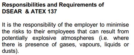
Hazardous area heating equipment is classified according to an EU directive introduced to protect people and plant in potentially explosive atmospheres, this hazardous area directive is known as ATEX.
ATEX & Heating Hazardous Areas Without Hidden Dangers
Flameless Is Blameless …
In sweeping terms, there are 3 pre-conditions for the ATEX directive to apply: the equipment a) must have its own effective source of ignition; b) be intended for use in a potentially explosive atmosphere and c) be under normal atmospheric conditions.
The ATEX directive consists of two EU directives describing the type of equipment (electrical and mechanical) and work environments allowed in an area with an explosive atmosphere.
ATEX derives its name from the French title of the 94/9/EC directive: Appareils destinés à être utilisés en ATmosphères EXplosibles.
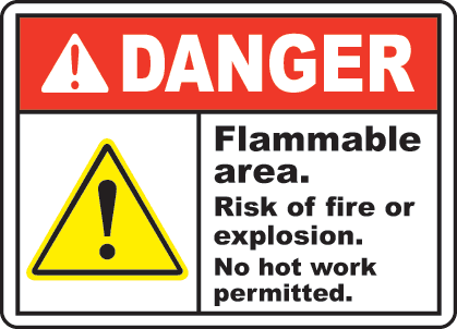
Naturally, the presence of invisible, inflammable gas or vapour mixtures could pose a serious threat to life where the Explosion Triangle could be triggered. Effective ignition sources in offshore working environments include sparks, open flames and flame arcs – consequently “hot-working” is prohibited offshore without safety working permits (WP’s).
Safety is not taken lightly anywhere in the offshore oil and gas sector and multiple tiers of responsibility prevail to prevent injury, accident or incident.
Take BP as an example.
Offshore Working Permits & Hazardous Area Locations
The Work Permit (WP) must be firstly registered as a Work Order (WO) request and attributed a risk-level by the offshore safety officer reflecting the work task, such as process pipework painting in Zone 1 hazardous areas.
Hot Working – this includes all temporary operations involving open flames or producing heat and/or sparks.
Several levels of authority exist to check and check again that the risk element of any proposed work task in a zoned hazardous area is scrutinised and minimised.
At BP, the Area Authority has responisibility for a given area and the Area Technician has operational responsibility for all activities in a given hazardous area.
Area technicians must measure the content of hydrocarbon gas in potential leakage points – pipework, flanges, seals, outlets etc – in the area around the hazardous area work site, immediately prior to work commencing.
Ultimately, the Offshore Installation Manager (OIM) has the overall responsibility for all activities on the field.
BP carry out a Safe Job Analysis (SJA) – a systematic and step-by-step review of all risk elements implemented prior to a specific task or operation so that all measures can be taken to remove or control any risk elements during the preparation for or performance of the WO request.
For instance, BP stipulate a Work Permit Level 1 is required for all high-risk work – this includes hot work in classified areas, where the classified area is defined as hazardous area Zone 0, Zone 1 and Zone 2 i.e. potentially explosive atmospheres dependent upon the concentration level and time period presence.
The application, planning, designation, administration, preparation and then implementation of “hot-working” permits is clearly complex, time-consuming and costly.
Portable ATEX electric heaters are certified under ATEX directive for safe use in potentially explosive atmospheres without resort to naked flames or hot work permit applications.
ICYMI 🎥 watch part of the new production and hotel platform being fitted as part of Valhall redevelopment #Norwaypic.twitter.com/3VUqrPjwrS
The drying and curing time of paint is affected by ambient temperature and relative humidity.
Low temperatures and excess humidity delays projects, maintenance and repair work – where shutdown periods need to be absolutely minimised to prevent downtime and associated lost revenue. Often painting and coating is subject to rescheduling and rescheduling. Curing takes longer. Costs overrun and deadlines are missed.
Not anymore– portable ATEX heaters with high ingress protection levels are tough, compact, powerful and easy to use whatever the weather. Fully ATEX certified for safe electrical heating in Zone 1 and Zone 2 hazardous area locations. Manufactured from marine grade 316 stainless steel with excellent corrosion resistance to offshore, sea-water atmospheres.
T&D’s portable ATEX heaters with a 15Kw output and powerful airflow (2130m cubed/hour) provides efficient hazardous area heating – ideal for warming enclosed workspaces which are “sheeted-off” for offshore shot blasting and industrial painting of gas compressor stations, tanks, pipework and structures.
Offshore Shotblasting & Painting. Designing-out risk through careful specification of electrical heating that eliminates or minimises danger is a key consideration for offshore multi-disciplined contractors. All thought and effort is geared towards preventing sparks in explosive atmospheres. Portable hazardous area heaters are designed to provide primary or supplementary heating for comfort or freeze protection in hazardous area (Gas or Dust) atmospheres.
Pictured : Zone 1 Paint Shop Containers – this paint shop and storage container manufactured by Trans Construction AS is typically used for storing and mixing paint. The hazardous area paintshop container is insulated to A60 and fully equipped with a mixer bench, storage lockers, ventilation supply and extract system.
Portable ATEX Heaters From Stock – call T&D.
Invitation – network, engage, promote
Thorne & Derrick are inviting you to join LinkedIn’s fastest growing Discussion Group – Process & Hazardous Area Industries : Heat Tracing, Gas Detection, Fluid Control & Flow Measurement. News, projects, videos, promotions, whitepapers, jobs, webinars, press plus much more. ABOUT US
Thorne & Derrick International are your single-source supplier of Electrical, Mechanical, Process & Instrumentation Equipment. T&D provide an outstanding service to UK and international customers – we are highly customer responsive and absolutely committed to providing a world-class service.
T&D supply utilities, power, renewable energy, construction, rail, manufacturing, food/beverage, mining, oil, gas and petrochemical industries – distributing 100,000+ products from 100+ manufacturers from multi-million pound stocks. Since 1985 we have established a solid reputation based on service, integrity and trust.
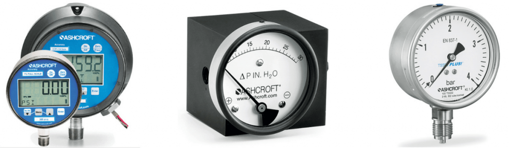
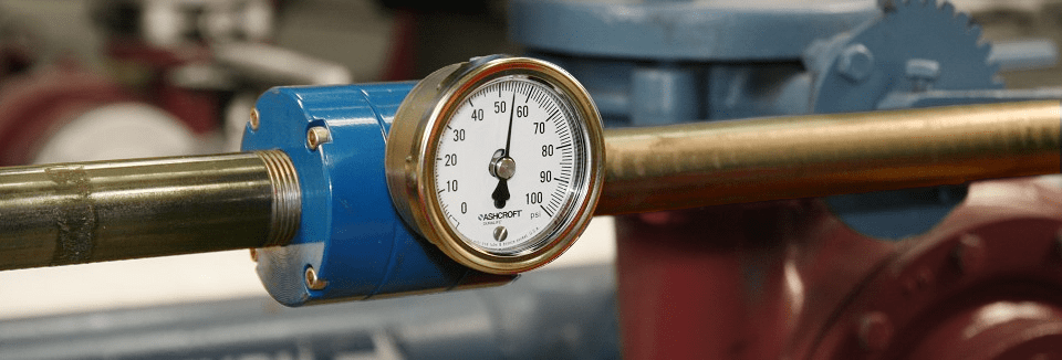
Ashcroftwas founded in 1852 by Edward Ashcroft and has developed into the world leading designer and manufacturer of pressure gauges used in many applications and industries – their instrumentation gauges were originally designed to protect the steam powered industry at the start of the industrial revolution in Great Britain.
“A world where your people, processes and profits are never at risk because Ashcroft measurement instruments are on the job.”
The Ashcroft vision is cemented by their mission of constantly pushing the limits of innovation to consistently deliver the world’s most trusted pressure gauges and measurement instruments.
Ashcroft pressure gauges provide accurate, reliable performance throughout global process and industrial markets.
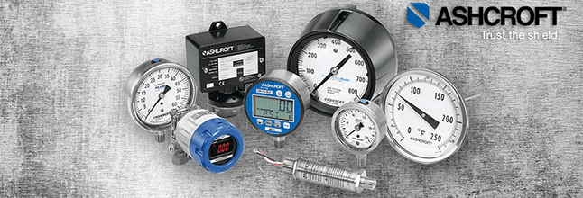
Ashcroft Pressure Gauges OVERVIEW
The range of Ashcroft Process Pressure gauges includes:
Ashcroft are the leading pressure and temperature instrumentation manufacturer of pressure gauges, test gauges and temperature gauges across all industries.
Ashcroft Pressure & Temperature Instrumentation – 160 Years Of Know-How & Experience
ashcroft Company History
Ashcroft protects assets and personnel in hundreds of countries – here are a few milestones in the Ashcroft company history:
1852 Edward Ashcroft acquired rights to produce Bourdon tubes
1852 Ashcroft Manufacturing Company is founded
1929 Introduced first phenolic gauge housing
1934 First to offer ±0.25% FS test gauge
1951 Moved world headquarters to Stratford, Connecticut
1973 Introduction of first precision digital pressure indicator
1977 Established Dresser Instruments Europe S.A. in Germany
1990 Cooperation with instrument manufacturer Nagano Keiki
1998 Developments in Ashcroft gauges, including PLUS!™ Performance™, Duratube™, FlutterGuard™, PowerFlex™movement and True Zero™
2016 & Beyond Ashcroft continues to introduce new, state-of-the-art instruments designed to meet their customer’s requirements
Industries
Applications for Ashcroft pressure gauges are extremely diverse with their pressure and temperature instrumentation being used to reduce costs and maintain the highest standards of process safety and environmental protection.
Ashcroft provide process temperature and pressure measurement instruments for industries including oil and gas, offshore, petrochemical, waste water, paper/pulp, renewable energy, power plants and mining/minerals industries.
Call us for Ashcroft Pressure & Temperature Measurement Instruments and Gauges.
Oil And Gas – Upstream, Mid-Stream & Downstream
Typically, Ashcroft instruments are divided by their application into three categories: 1) industrial and life 2) food and beverage 3) medical services.
Within these areas, there are more specific industries and applications to choose from. All of which is designed to make selecting the correct pressure gauge as simple as possible.
Ashcroft pressure gauges and process instruments are designed to perform in harsh conditions and are often deployed in the the wellhead, offshore rig and shale field – this includes NACEcompliant gauges, seals and SIL 3 capable switches.
Ashcroft provide pre-assembled gauges instrument/diaphragm seal combinations to ensure that corrosive caustics will not threaten any operation or personnel.
Within many industries, Ashcroft products provide filtration, pressure, flow and level measurement all requiring precise, continuous monitoring and control whilst also overcoming corrosive media, effluents, solids, vibration and pulsation. Constantly providing accurate measurements that prevent unplanned shutdowns and dangerous conditions.
Power Industry
Within the power industry, Ashcroft pressure gauges are used to help meet the demand for low energy prices, green energy production and a consistent, reliable service. The range of pressure measurement instruments have been developed to help sustain a power plant that is clean burning, efficient and in continuous service.
Ashcroft pressure gauges can monitor pressure levels in harsh environments and control pressure under the most extreme conditions. In hazardous area locations, safety is assured with Ashcroft explosion proof pressure switches certified to international hazardous Class/Division/Zone classifications.
MetaLs, Minerals And Mining Industry
Within the mining industry, Ashcroft products can help control damage before it occurs. Ashcroft focus is to protect lives, plant and equipment and countering everyday hazards that are naturally associated with this industry.
Purpose built pressure gauges for use in hazardous areas and destructive processes are suitable for use when dangerous gases are present and explosive atmospheres are commonplace. Even when monitoring the pressure of medias that are likely to clog a gauge, this can be overcome through an isolation ring, ensuring an uninterrupted process flow with continuously accurate measurements.
Pressure Gauges: NACE SIL ATEX Compliant
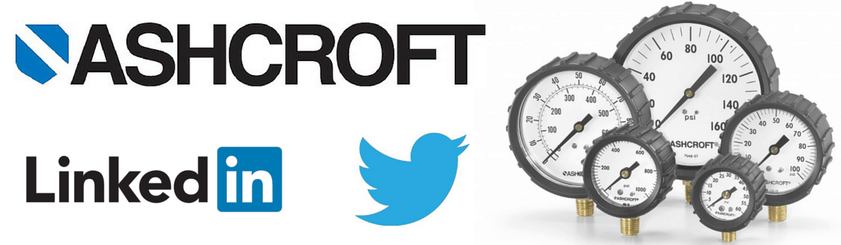
Ashcroft Social Media
Folllow Ashcroft on Twitter and LinkedIn for daily updates, new product information and discussions.
Ashcroft Pressure Gauges – Engage On Social Media Social
Thorne & Derrick are inviting you to join LinkedIn’s fastest growing Discussion Group – Process & Hazardous Area Industries : Heat Tracing, Gas Detection, Fluid Control & Flow Measurement. News, projects, videos, promotions, whitepapers, jobs, webinars, press plus much more.
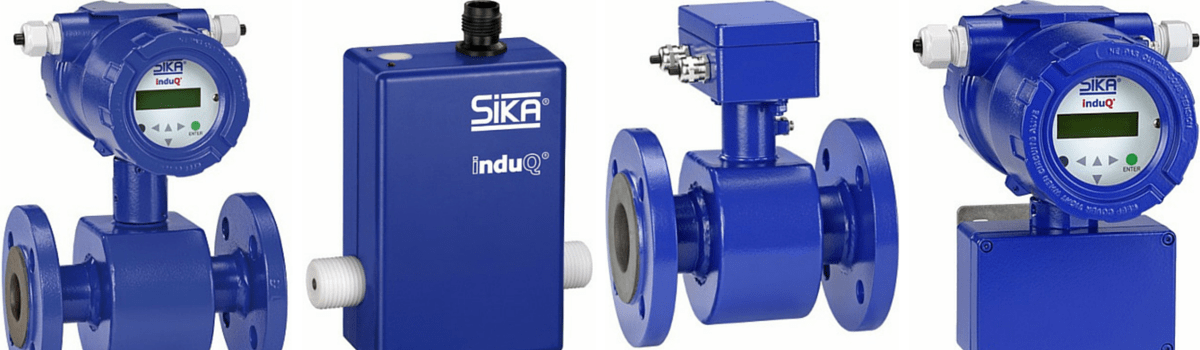
Magmeters: Magnetic Flow Sensors for Conductive Fluids
Magmeters (or magnetic flow meters) from Sika are fluid measurement instruments that are used globally in many processing applications and as a figure make up around 20% of all installations.
The term Magmeter is an amalgamation of the terms magnetic and meter.
The Magmeter is constructed from a non-magnetic flow tube, electrodes, liner and electromagnets to generate a magnetic field. These magnetic flow meters are used to typically measure fluid and flow rate which must be a conductive fluid.
As a rule, the minimum conductivity level of a fluid to measured with a Magmeter is 5 microS/cm.
Magmeter Inductive Flow Measurement Instruments
Magmeters
Magnetic Inductive Flow Measurement
Magmeters are generally used because of their obstruction less design, linear signal output, high levels of accuracy and corrosion resistant wetted components. As there are no moving components throughout the flow meter there is nothing to cause an obstruction and therefore the pressure drop through the meter is virtually zero.
In addition to there being no pressure drop, the lack of moving parts also results in there being no wear on the magnetic flow meter throughout its lifetime.
The Magmeter contains an electromagnetic coil that produces the magnetic field that usually surrounds the outside of the non-magnetic pipe called the flow tube. An alternating current passes through the coils generating a magnetic field inside the flow tube.
The liquid being measured then passes through the flow tube perpendicular to the plane of the magnetic field that has been created. Typically a metal meter body is manufactured from 304 stainless steel that has strong non-magnetic properties allowing the magnetic field to pass through the meter body into the pipe area and therefore provide the flow signal.
The insulated liner that is installed in between the meter body and the electrodes is used to prevent the flow signal from being shorted-out as the voltage developed across the electrodes is generally a few millivolts in power.
Magnetic Flow Meter
Magmeters To Meet Every Requirement
SIKA 3 Types
There are 3 Magmeters available in the series of magnetic flow measurement instruments – Sika VMI, VMZ and VMM.
Each Magmeter has been manufactured for different application and developed specifically for individual applications.
HOW TO SELECT YOUR MAGMETER
Is the fluid conductive or water based?
Is the fluid or slurry abrasive?
Do you require an integral display or remote display?
Do you require an analogue output?
What is the minimum and maximum flow rate for the flow meter?
What is the minimum and maximum process pressure?
What is the minimum and maximum process temperature?
Is the fluid chemically compatible with the flow meter wetted parts?
What is the size of the pipe?
Is the pipe always full?
SIKA: Variable flow meters determine the volume flow of liquids or gases in pipelines.
How To Maximise Your Magmeter
Magmeters are often used in applications where the media being monitored is harsh i.e sludge, sewage or other similar liquids. The magmeter is preferred due to its non-intrusive design, reliability, low maintenance and accuracy.
Magmeters have a larger range of flow than traditional meters however despite the rugged design and simplicity of use, there are still factors that can be incorporated to improve the performance of your electromagnetic flow meter.
Ensure the flow media is above the minimum conductivity level – this measure ensures the electromotive force is able to drive the voltage and current into the signal electrodes.
Make sure the meter tube is full at all times – by carrying out this check, the magmeter will not produce inaccurate or erratic readings and as most magmeters automatically assume the flow tube is full, they cannot detect a half empty pipe. Methods to ensure full liquid flow include:
positive head pressure from pumps
uphill grades
vertical installation
positioning the meter in the lowest point of a plumbing trap
Ensure the magmeter is installed on a length of pipe with straight pipe before and after the meter.
Make sure that provisions have been made proper connections and adequate grounding. Again, this will prevent the magmeter from giving inaccurate or erratic readings. The magmeter relies on a potential earth ground in order to operate.
Know the metering application – by knowing what the magmeter application is, it is easier to select the correct converter orientation.
Avoid any heavy vibration – Heavy external vibrations caused by a generator or diesel driven pump may damage the signal converter electronics. In order to mitigate the damage caused by vibration it is advisable to construct a concrete or steel support to absorb the vibrations.
Avoid wide temperature variations – The magmeter electronics are sensitive and it is a good idea to cover the meter sensor to ensure accurate, consistent readings.
Avoid any extreme heat from sources such as welding from going near the magmeter to ensure the liner and outer coatings do not become damaged. Any welding should be completed prior to installation of the flow sensor or alternatively compression and transition couplings can be used to avoid welding altogether.
SIKA VMI Magmeter
Due to its robust, strong metal housing and stable process connections, the Sika VMI Magmeter is particularly suited to applications within mechanical engineering and plant construction. The
VMI Magmeter – Electromagnetic Flow Sensor
design of the VMI means it is also suitable for use at high temperatures and high process pressures. In addition, the instrument can be supplied in three different sizes: VMI 07, VMI 10 and VMI 20.
The Sika VMZ Magmeter is a magnetic inductive flow meter for electrically conductive liquids that has been designed specifically for original equipment manufacturer (OEM) applications. The VMZ
VMZ Magmeter – OEM Applications
incorporates plastic components that are cost optimsed resulting in a lightweight design that it is available in six flow ranges.
The specifications of the VMZ magmeters are:
VMZ 030 Magnetic flow meter – Nominal diameter DN 3 Flow range 0.1…2 l/min
VMZ 081 Magnetic flow meter – Nominal diameter DN 8 Flow range 0.25…5 l/min
VMZ 082 Magnetic flow meter – Nominal diameter DN 8 Flow range 1…20 l/min
VMZ 153 Magnetic flow meter – Nominal diameter DN 15 Flow range 2.5…50 l/min
VMZ 204 Magnetic flow meter – Nominal diameter DN 20 Flow range 5…100 l/min
VMZ 205 Magnetic flow meter – Nominal diameter DN 20 Flow range 10…200 l/min
SIKA VMM Magmeter
The Sika VMM magnetic flow meters are suitable for use in harsh ambient conditions due to their robust design and construction. The steel construction is fully welded and therefore has great resistance to any potential interference.
VMM Magmeter – Compact Electro Magnetic Flow Sensor
The range of Sika VMM Magmeter nominal diameters cover fluid measurement requirements from medium flow rates right up to 10 m/s. The sensors are manufactured from high quality materials and provide solutions to numerous application possibilities.
The specifications of the nine variations of the VMM Magmeter are:
VMM32 Magnetic Inductive Flow Sensor – Nominal diameter DN 32 Flow range 0.25…10 m/s 0.72…29 m³/h
VMM40 Magnetic Inductive Flow Sensor – Nominal diameter DN 40 Flow range 0.25…10 m/s 1.15…45.2 m³/h
VMM50 Magnetic Inductive Flow Sensor – Nominal diameter DN 50 Flow range 0.25…10 m/s 1.8…70.7 m³/h
VMM65 Magnetic Inductive Flow Sensor – Nominal diameter DN 65 Flow range 0.25…10 m/s 3…119.5 m³/h
VMM80 Magnetic Inductive Flow Sensor – Nominal diameter DN 80 Flow range 0.25…10 m/s 4.5…181 m³/h
VMM100 Magnetic Inductive Flow Sensor – Nominal diameter DN 100 Flow range 0.25…10 m/s 7…282.7 m³/h
VMM125 Magnetic Inductive Flow Sensor – Nominal diameter DN 125 Flow range 0.25…10 m/s 11…441.8 m³/h
VMM150 Magnetic Inductive Flow Sensor – Nominal diameter DN 150 Flow range 0.25…10 m/s 16…636.2 m³/h
VMM200 Magnetic Inductive Flow Sensor – Nominal diameter DN 200 Flow range 0.25…10 m/s 28…1131 m³/h
Magmeter Types
Sika VMM Magmeters are available as either a compact or separate type installation – compact Magmeters are supplied as a complete unit whereas separate flow sensors are supplied in multiple sections.
Thorne & Derrick – Metering & Measurement Specialists. Gas, Heat & Water Meters for Commercial & Industrial Applications.
Invitation – network, engage, promote
Thorne & Derrick are inviting you to join LinkedIn’s fastest growing Discussion Group – Process & Hazardous Area Industries : Heat Tracing, Gas Detection, Fluid Control & Flow Measurement. News, projects, videos, promotions, whitepapers, jobs, webinars, press plus much more. ABOUT US
Thorne & Derrick International are your single-source supplier of Electrical, Mechanical, Process & Instrumentation Equipment. T&D provide an outstanding service to UK and international customers – we are highly customer responsive and absolutely committed to providing a world-class service.
T&D supply utilities, power, renewable energy, construction, rail, manufacturing, food/beverage, mining, oil, gas and petrochemical industries – distributing 100,000+ products from 100+ manufacturers from multi-million pound stocks. Since 1985 we have established a solid reputation based on service, integrity and trust.
Thermostatic Mixing Valves – The Easy Guide to TMV3 Approval
By Chris Dodds : estimated reading time 8 minutes
NHS Estates together with manufacturers of TMV’s (thermostatic mixing valves) co-operated to establish a Third Party Certification scheme (TMV3 Scheme) – the Scheme tests and certifies TMV’s for enhanced thermal performance and shut-off for specific applications as described in the NHS Estates Model engineering Specification D08.
An installed approved mixing valve will only be regarded as continuing to satisfy the requirements of the TMV3 Scheme providing the supply conditions, commissioning and in-service test requirements are as stipulated by manufacturers of the valve.
1. Introduction
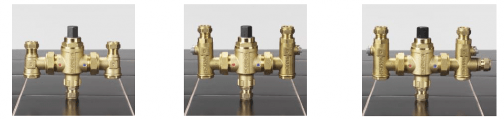
BuildCert approves two categories of Thermostatic Mixing Valves; TMV2 and TMV3. The different valve types are shown below.
TMV3 approval is for thermostatic valves for use in Healthcare and Commercial situations. It certifies that the valves it approves conform to the performance requirements of NHS specification D 08.
Types of valves:
Type 1 – A mechanical mixing valves with maximum temperature stop (including single lever taps).
Type 2 – A thermostatic mixing valve which conform to BS EN 1111 and BS EN1287 (originally BS 1415 Part 2). These can have a maximum temperature stop.
Type 3 – A thermostatic mixing valve with enhanced thermal performance complying with NHS Estates requirements.
1.1. Pre-approval requirements
The BuildCert approval Scheme requires the following as a pre-requisite for approval.
All manufacturers and factors must have ISO 9001 accreditation covering valve manufacture, production and handling or be audited by a BuildCert appointed Auditor.
All BuildCert approval holders must become a member of the BuildCert Scheme.
The Scheme requires three test valves be selected from a batch of 30 production valves. Valve selection may be undertaken by an independent 3rd party (if this is the case then BuildCert will require a signed declaration from that 3rd party).
The Installation and Maintenance documents (I&M) must include information stated by the Scheme (see Section 5).
Upon gaining approval the valve must meet the Schemes audit requirements (performance tested twice within the 5 year approval period).
Manufacturers of Thermostatic mixing valves can demonstrate compliance with the BuildCert quality requirements by supplying the Scheme with a copy of a valid ISO 9001 certificate and scope of accreditation or an approved quality system. Where this cannot be supplied a quality audit will be conducted by the scheme to verify compliance with the requirements of the Scheme.
A Primary factor is a company/individual who does not manufacture the valve but distributes a certified valve under his own trade name, the product having only cosmetic changes. An approval for the primary factor is sometimes referred to as a piggyback approval.
1.2. Recommended maximum mixed water outlet temperatures TMV3
The BuildCert/TMV Scheme recommends the maximum mixed hot water temperatures for safe use for the installations below.
44°C for bath fill (46°C for assisted bathing)
41°C For shower applications.
38°C For bidet applications
1.3. Operating conditions
Type 3 Thermostatic Mixing Valves are suitable for use when the hot and cold water supplies to the valves are within the limits specified for each operating range and where the mixed water temperature is set during commissioning at the appropriate temperature for its intended use (designation) see table below.
Only thermostatic mixing valves with no user-accessible adjustment of the mixed water temperature should be used where more than one outlet may discharge simultaneously when operated by more than one user at the same time.
Type 3 Thermostatic mixing valves having user-accessible adjustment may not be used for supplying two different maximum mixed water temperatures, e.g.
Shower/Bath Mixers unless the movement of the diverter mechanism or some other device will automatically adjust the temperature to the maximum mixed water temperature allowed for that mixed water outlet.
The maximum nominal size of mixing valves covered by this standard is DN25.
Conditions For Normal Use
High Pressure
Low Pressure
Maximum Static Pressure
10 bar
10 bar
Flow Pressure, Hot & Cold
Between 1.0 and 5.0 bar
Between 0.2 and 1.0 bar
Hot Supply Temperature
Between 52ºC and 65ºC
Between 52ºC and 65ºC
Cold Supply Temperature
Between 5ºC and 20ºC
Between 5ºC and 20ºC
1.4. Designation
Some valves will be suitable for a number of purposes (or across a range of designations).
Designation Codes
HP-B
High Pressure
Bidet – Maximum Temperature 38ºC
HP-S
High Pressure
Shower – Maximum Temperature 41ºC
HP-W
High Pressure
Washbasin – Maximum Temperature 41ºC
HP-T44
High Pressure
Bath with fill temperature up to 44ºC
HP-T46
High Pressure
Bath with fill temperature up to 46ºC (Assisted bathing)
HP-D44
High Pressure
Bath with fill temperature up to 44ºC and shower up to 41ºC
HP-D46
High Pressure
Bath with fill temperature up to 46ºC (Assisted bathing) and shower up to 41ºC
LP-B
Low Pressure
Bidet – Maximum Temperature 38ºC
LP-S
Low Pressure
Shower – Maximum Temperature 41ºC
LP-W
Low Pressure
Washbasin – Maximum Temperature 41ºC
LP-T44
Low Pressure
Bath with fill temperature up to 44ºC
LP-T46
Low Pressure
Bath with fill temperature up to 46ºC (Assisted bathing)
LP-D44
Low Pressure
Bath with fill temperature up to 44ºC and shower up to 41ºC
LP-D46
Low Pressure
Bath with fill temperature up to 46ºC (Assisted bathing) and shower up to 41ºC
Key
B – Bidet, S – Shower, W – Washbasin, T – Tub (Bath), D – Diverter, HP – High Pressure, LP – Low Pressure
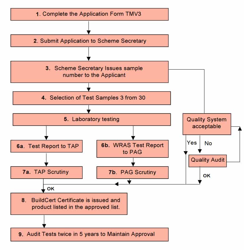
Complete and return the form TMV3 to BuildCert along with the Installation and Maintenance document, ISO 9001 documentation and scope of accreditation for the manufacturer and the applicant.
Arrange the WRAS approval of the valve.
BuildCert will inform the applicant in writing of the allocated BuildCert sample number and either request verification of issues or request sample valves for test, an administration invoice will be appended.
The applicant sends test sample valves to the test house.
The test house undertakes the mechanical testing.
The test house will forward the test report and the test sample valve B to BuildCert.
The test report, sample valve and documentation will be presented to the BuildCert Technical Assessment Panel (TAP) for verification and agreement.
An approval letter, Certificate and invoice will be forwarded to the applicant, as appropriate.
The valve details will be entered into the approved valve list on the BuildCert website.
3. Factored approval (piggyback)
Complete and return the form TMV3 to BuildCert along with the installation and maintenance document and the ISO 9001 documentation with scope of accreditation for the manufacturer and the applicant. Also enclose a completed WRAS F2 application form.
BuildCert requires a letter from the original license holder giving consent for the applicant to use the original TMV approval. The letter must state the original BuildCert and WRAS approval numbers. A written statement is required that the existing approved product and the piggyback product are identical in all respects except identification and or handle variants.
BuildCert will then inform the applicant in writing of the allocated BuildCert sample number and either request verification of issues or request a sample valve for verification, an administration invoice will be appended.
The applicant will send a sample valve to BuildCert.
The sample valve and its documentation will then be presented to the BuildCert Technical Assessment Panel (TAP) for verification and agreement.
WRAS Approval will be arranged.
An approval letter and Certificate and invoice will be forwarded to the applicant.
The valve details will be entered into the approved valve list on the BuildCert website.
4. Flow chart of full TMV3 approval
5. Information to be included in the Information and Maintenance documentation
The following points are to be included in Installation and Maintenance (I&M) Documents.
Information upon the designation of use i.e.HP-T46, LP-S etc.
Information upon the commissioning of the valve. This will include:
a. Operating pressures for the valve.
b. The water supply temperatures for the valve.
c. Method of adjusting the mixed water temperature.
d. Method for commissioning the valve.
e. Mixed water temperature.
f. Method for performing the In-service tests.
To facilitate the information required in 2) a) b) and e) and to present the information in a standardized fashion, the relevant information contained in Tables 1 and 2 in the NHS document D08 is to be included in a tabular format within the I & M documentation.
Information upon the frequency of in-service tests and service work.
Information on the Backflow prevention devices that will be fitted, including the specification of the Backflow preventer, i.e. size, type and position (inbody / handset / hose / tail / servicing valve). If the Backflow preventer is not supplied as part of the package then details of the type of device to be used are to be specified
Position of isolating valves if provided, if not provided the need for isolation valves and their position when fitted.
Position of strainers if provided, if not provided their position if fitted at the time of installation.
Inclusion of temperature differential characteristics of the valve.
Click HORNE TMV’s for complete specifications, product data, installation guidelines and ordering information about Thermostatic Mixing Valves.
Thorne & Derrick are inviting you to join LinkedIn’s fastest growing Discussion Group – Process & Hazardous Area Industries : Heat Tracing, Gas Detection, Fluid Control & Flow Measurement. News, projects, videos, promotions, whitepapers, jobs, webinars, press plus much more.
ABOUT US
Thorne & Derrick International are your single-source supplier of Electrical, Mechanical, Process & Instrumentation Equipment. T&D provide an outstanding service to UK and international customers – we are highly customer responsive and absolutely committed to providing a world-class service.
T&D supply utilities, power, renewable energy, construction, rail, manufacturing, food/beverage, mining, oil, gas and petrochemical industries – distributing 100,000+ products from 100+ manufacturers from multi-million pound stocks. Since 1985 we have established a solid reputation based on service, integrity and trust.
Press Release Date: 02.04.2020 uploaded by Chris Dodds (T&D Sales + Marketing Manager) World’s First Fully Certified ATEX Doors Thorne & Derrick International, the Experts in Equipment for Explosive Atmospheres, today announce the signing of a Commercial Distribution Agreement...
Press Release Date: 04.07.2019 uploaded by Chris Dodds (T&D Sales + Marketing Manager) Category: Stockist Distributor Agreement Announcement Thorne & Derrick International announce that they have signed a Preferred Distributor Agreement with Raytec, the world leading manufacturer of LED...


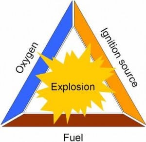 Naturally, the presence of invisible, inflammable gas or vapour mixtures could pose a serious threat to life where the Explosion Triangle could be triggered. Effective ignition sources in offshore working environments include sparks, open flames and flame arcs – consequently “hot-working” is prohibited offshore without safety working permits (WP’s).