Lone Worker Protection
Ecom Personal Emergency Response Communication Solutions
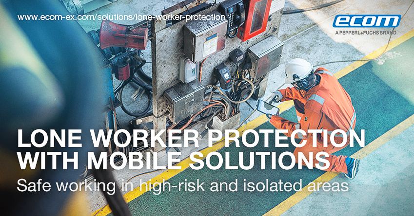
The safety of their workforce is key for every employer. With mobile solutions, Lone Worker Protection concepts can be implemented cost-effectively and efficiently.
By opting for the Smart-Ex® 02 or the Ex-Handy 10 you are not only acquiring a smartphone that is rugged, reliable and intrinsically safe, but one that also caters for the safety of your employees around the world.
Ecom’s intrinsically safe smartphones with lone worker protection (LWP) functionality have been specifically designed for the safety of people working alone. The requirements of the users vary as they are from various industrial sectors requiring modern communication technology with personal emergency response devices.
This was the drive for Ecom to provide safe working in high-risk and isolated areas. These phones are able to help locate anyone who has suffered an accident and immediately initiate the necessary measures.
Employees are exposed to higher risks and rely on fast assistance in case of emergency. With increased risk, the use of a personal emergency response system is recommended or even mandatory in case of critical hazard. In the case of deficiencies relating to workplace safety, injuries, accidents and subsequent damage to people or plants may occur.
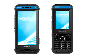
Ecom Smart-Ex 02 & Ex-Handy 10
Lone Worker Protection Features
- Lone worker protection and mobile phone in one
- Programmable 3D motion sensor for: Inclination alarm, impact alarm, escape alarm, lack of movement
- Programmable dead man’s switch
- Alarm button for deliberately triggered alarms
- Technical alarms: E2E check, battery status, connection to GSM or 3G/4G network
- Connection to renowned security centers also possible
- Alert for incoming messages with subsequent read receipt sent to the alarm control unit
- Visualisation of the alarm modes in the display
- Loud audible alarm
- Programmable geo zones
- Communication via latest technology like 4G/LTE while SMS/GPRS is still available as a backup
For people working in hazardous areas or extensive terrains, companies must ensure that the rescue chain is always guaranteed. The mobile communication device must also be triggered if the injured person is incapacitated without anyone noticing the accident. Ecom smartphones and featurephones are components of a tested and according to BGR-139 certified Lone-Worker-Protection-Solution or person-emergency-response system from Swissphone.
They are equipped with dedicated side buttons for one-touch access to PTT services such as the yellow PTT button and the red emergency button. Together with fully developed Lone-Worker-Protection-Applications from well-known vendors on the market, these mobile solutions reliably protect the user and document the process.
Smartphone or tablet send an emergency signal to the control center in case of emergency by pushing the button (will-dependent emergency call) as well as by triggering the position or impact sensor (automatic emergency call). In case of a triggered alarm, an automatic call setup is the standard procedures for checking the constitution of the employee.
FURTHER READING
ELECTRICAL & PROCESS INSTRUMENTATION EQUIPMENT
FOR EXPLOSIVE ATMOSPHERES
Thorne & Derrick are Specialist Distributors of Hazardous Area & Explosion Proof Equipment with IECEx & ATEX Certifications to the onshore and offshore oil, gas, petrochemicals and process industries.
Key Product Categories: ATEX Doors | Control Panels | Plugs & Sockets | Isolators | Enclosures & Junction Boxes | Lighting | Control Stations | Motor Starters | Heat Trace Cables & Systems | Gas Detection & Detectors | Fire Detection & Detectors | Heat Detectors | Electrical Heating & Heaters
 Also Process Instrumentation Products: Ashcroft Pressure Gauges | ASCO Valves | Katronic Flow Meters | KROHNE Flow Meters | VEGA Level Sensors | Rotronic Temperature & Humidity Sensors | SIKA Pressure Gauges
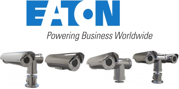
Hazardous Area Camera Station With 70 Degree Enhancement
Hazardous Area Camera Station
70 Degree Enhancement
Eaton is pleased to announce that a selected range of the Oxalis CCTV Camera Stations of hazardous & safe area camera stations has now been certified for +70˚C operational temperature to meet the demands of the harshest high ambient temperature environments.
This enhancement is the result of extensive internal and external testing, and the products are now ATEX and IECEx certified with a 10˚C increase on the previous upper ambient temperature of +60˚C T4/T5 to +70˚C T4 & +65˚C T5 (configuration dependent).
The increased temperature ranges have now become common place in many Middle East specifications with the requirement of extended operating temperatures. This enhancement in the upper ambient temperature rating has been made possible by subtle product design optimisation,decreasing the operating temperature and increasing operating longevity.
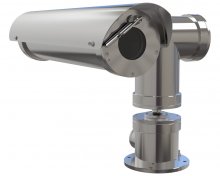
ATEX CCTV CAMERA STATIONS
Camera surveillance systems provide a complete view of all areas and processes on a site. A system can be accessed and managed from one or more control stations on site or remote. CCTV surveillance is vital for the coordination of appropriate response in critical situations.
With multiple Ex certification, our camera range is suitable for world-wide installation in Europe, the Americas, Middle East and Asia – global classifications in including ATEX, IECEx, INMETRO, TR CU, cLCus, CSA, CNEx, CCOE, CERTEx.

ZONE 1 & ZONE 2 CCTV CAMERA STATIONS
The Eaton Oxalis hazardous area CCTV are offered with global ATEX, IECEx and UL approvals.
- Oxalis XP – Explosion Proof PTZ camera stations
- Oxalis XF – Explosion Proof fixed camera stations
- Oxalis XT – Explosion Proof PTZ camera stations
- Oxalis EXIR40F – Explosion Proof fixed camera stations
- Oxalis XC – Explosion Proof PTZ camera stations
ELECTRICAL & PROCESS INSTRUMENTATION EQUIPMENT
FOR EXPLOSIVE ATMOSPHERES
Thorne & Derrick are Specialist Distributors of Hazardous Area & Explosion Proof Equipment with IECEx & ATEX Certifications to the onshore and offshore oil, gas, petrochemicals and process industries.
Key Product Categories: Control Panels | Plugs & Sockets | Isolators | Enclosures & Junction Boxes | Lighting | Control Stations | Motor Starters | Heat Trace Cables & Systems | Gas Detection & Detectors | Fire Detection & Detectors | Heat Detectors | Electrical Heating & Heaters
Also Process Instrumentation Products: Ashcroft Pressure Gauges | ASCO Valves | Katronic Flow Meters | KROHNE Flow Meters | VEGA Level Sensors | Rotronic Temperature & Humidity Sensors | SIKA Pressure Gauges
UL Certification For Eaton Oxalis CCTV Range
Eaton Oxalis
CCTV Camera Station
Eaton is pleased to announce an enhancement to its Oxalis CCTV Camera Station range used in hazardous & harsh environments.The entire range of Eaton Oxalis CCTV Camera Stations has now been certified and approved by UL for both hazardous and ordinary locations in accordance with OSHA requirements.
Paying particular attention to the feedback gained at the installer level, all Class/Division products come with NPT entries as standard and the PTZ models incorporate a new base design with dual cable entries & easy access for cable termination.
In addition the range also includes a thermal offering across the Fixed, PTZ and Dual in both Ex and Safe Area models.
ATEX CCTV CAMERA STATIONS
Camera surveillance systems provide a complete view of all areas and processes on a site. A system can be accessed and managed from one or more control stations on site or remote. CCTV surveillance is vital for the coordination of appropriate response in critical situations.
With multiple Ex certification, our camera range is suitable for world-wide installation in Europe, the Americas, Middle East and Asia – global classifications in including ATEX, IECEx, INMETRO, TR CU, cLCus, CSA, CNEx, CCOE, CERTEx.
ZONE 1 & ZONE 2 CCTV CAMERA STATIONS
The Eaton Oxalis hazardous area CCTV are offered with global ATEX, IECEx and UL approvals.
- Oxalis XP – Explosion Proof PTZ camera stations
- Oxalis XF – Explosion Proof fixed camera stations
- Oxalis XT – Explosion Proof PTZ camera stations
- Oxalis EXIR40F – Explosion Proof fixed camera stations
- Oxalis XC – Explosion Proof PTZ camera stations
ELECTRICAL & PROCESS INSTRUMENTATION EQUIPMENT
FOR EXPLOSIVE ATMOSPHERES
Thorne & Derrick are Specialist Distributors of Hazardous Area & Explosion Proof Equipment with IECEx & ATEX Certifications to the onshore and offshore oil, gas, petrochemicals and process industries.
Key Product Categories: Control Panels | Plugs & Sockets | Isolators | Enclosures & Junction Boxes | Lighting | Control Stations | Motor Starters | Heat Trace Cables & Systems | Gas Detection & Detectors | Fire Detection & Detectors | Heat Detectors | Electrical Heating & Heaters
Also Process Instrumentation Products: Ashcroft Pressure Gauges | ASCO Valves | Katronic Flow Meters | KROHNE Flow Meters | VEGA Level Sensors | Rotronic Temperature & Humidity Sensors | SIKA Pressure Gauges
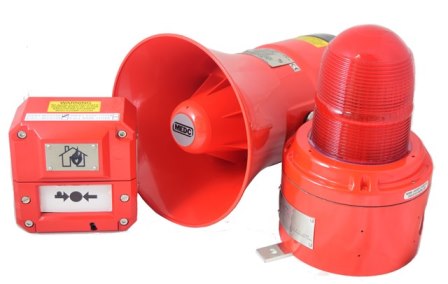
CCCF certification for MEDC BG Manual Alarm Call Points
MEDC BG Manual Alarm Call Points
CCCF Certification
Eaton Hazardous Area Communications group has an exciting new enhancement to its MEDC product line with the introduction of CCCF certification.
The CCCF products include the BG break glass call point, XB15 xenon strobe beacon and the DB3B electronic high power sounder, enhancing the ranges’ already extensive approvals list, including CQST.
This enhancement is a result of extensive internal and external testing, leading to Eaton’s unique position of providing a call point, beacon and sounder with both CCCF and CQST approvals, which allows the products to be installed on Chinese fire alarm systems with CQST hazardous areas classification.
These selected products are a valuable addition to any fire system, with a certified operation temperature reaching +70°C, lightweight GRP construction, and an ingress protection rating of IP66 and IP67. The maximum output for the DB3B is 122dB (@1m +/- 3dB) and the XB15 up to 382Cd.
ATEX Manual Alarm Call Points
Eaton MEDC BG are manual fire alarm ATEX call points designed for use in flammable atmospheres and harsh environmental conditions in ATEX Zone 1 and Zone 2 hazardous areas.
The Eaton MEDC BG range of Zone 1 & Zone 2 call point caters for numerous options such as variety of colours, LED indication, earth continuity, double switch, etc

ATEX Beacons
Eaton MEDC XB15 are ATEX beacons that have been designed for use in potentially explosive atmospheres and harsh environmental conditions in ATEX & IECEx Zone 1 and Zone 2 hazardous areas.
In addition to the standard worldwide certificates, EN54-23 and SIL1 are both now available. As well as the MEDC XB15 ATEX beacons being certified from -55°C to + 70°C , the new control circuits have been designed to consistently energise at -55°C.

ATEX Sounders
Eaton MEDC DB3B are high power explosion proof ATEX sounders introduced as a replacement for the current DB3 with improved functionality and performance.
The hazardous area sounder is certified for use in a wide range of temperatures from -55ºC to +70ºC in ATEX & IECEx Zone 1 and Zone 2 hazardous areas.The flexibility of the range continues with a wide range of supply voltages. The short flare option is worthy addition to the range offering a high SPL in a compact unit.
ELECTRICAL & PROCESS INSTRUMENTATION EQUIPMENT
FOR EXPLOSIVE ATMOSPHERES
Thorne & Derrick are Specialist Distributors of Hazardous Area & Explosion Proof Equipment with IECEx & ATEX Certifications to the onshore and offshore oil, gas, petrochemicals and process industries.
Key Product Categories: Control Panels | Plugs & Sockets | Isolators | Enclosures & Junction Boxes | Lighting | Control Stations | Motor Starters | Heat Trace Cables & Systems | Gas Detection & Detectors | Fire Detection & Detectors | Heat Detectors | Electrical Heating & Heaters
Also Process Instrumentation Products: Ashcroft Pressure Gauges | ASCO Valves | Katronic Flow Meters | KROHNE Flow Meters | VEGA Level Sensors | Rotronic Temperature & Humidity Sensors | SIKA Pressure Gauges
Ex d Flameproof
Ex d Certification for Hazardous Area Electrical Equipment
This article by Jacob Thumberger, Business Assurance Product Certification Specialist at DNV GL – Business Assurance, looks in detail at the general requirements for obtaining Ex d certification for hazardous area location equipment such as enclosures.
Whereas other protection types aim to prevent an explosion by removing one of the legs of the fire triangle, the intent of the Ex d type of protection is to contain/quench an explosion by use of a suitably designed enclosure where all of the paths from the inside of the enclosure to the outside atmosphere, called flamepaths, are tightly controlled.
In order to contain an explosion, the enclosure walls must be suitably thick. The exact thickness needed will depend on the enclosure volume, the internal configuration, and the specific explosive gases that the enclosure is intended to be used with.
In order to quench an explosion, all flameproof joints must adhere to strict requirements. The exact requirements depend on what kind of joints are utilized (flanged, cylindrical, spigot, threaded, etc.), and the flammable gases that will be present. In all cases, the intent is the same: prevent an internal ignition from being transmitted outside the enclosure.
For threaded joints, this is accomplished by ensuring a minimum number of engaged threads, in addition to minimum thread length and tolerance requirements. For non-threaded joints, this is accomplished by maintaining minimum width and maximum gap values for the flameproof joint, in addition to testing for non-transmission of an internal ignition. Specific details on these requirements can be found in Clause 5 of EN/IEC 60079-1.
General Requirements
for Obtaining Ex d Certification
As with any hazardous area certification, all Ex d designs must be assessed and tested against the applicable requirements of EN/IEC 60079-0 (General Requirements) and also against the requirements of EN/IEC 60079-1 (Flameproof Enclosures).
For AEx certification, the design is evaluated against the U.S. versions of the 60079-0 and 60079-1 standards that contain national deviations that make them compatible with Article 505 of the National Electrical Code (NFPA 70).
The requirements for flameproof enclosures to be used under the Class/Division system in the National Electrical Code have different construction and test requirements. As a minimum, this includes:
– Determination of maximum temperature rise (either via assessment or testing) and assignment of temperature classification (i.e. T4 or T135°C). These requirements are defined in Clause 5.
– Assessment of enclosure materials, both metallic (Clause 8) and non-metallic (Clause 7).
– Assessment of any safety critical fasteners (Clause 9).
o Note: These requirements are supplemented by Clause 11 of EN/IEC 60079-1.
– Verification of earthing provisions (Clause 15).
– Assessment of enclosure entries (Clause 16).
o Note: These requirements are supplemented by Clause 13 of EN/IEC 60079-1.
– Enclosure testing, including resistance to impact, drop test (portable equipment), and ingress protection testing (where IP rating is safety critical). These requirements are detailed in Clause 26.4.
o Note: Where critical enclosures are constructed of non-metallic materials, thermal endurance to heat/cold is also applicable, and is conducted prior to all other enclosure tests (Clause 26.4.1.2).
– Verification of product marking details, including any applicable warnings (Clause 29).
– Verification that product instructions contain all applicable details, including a recapitulation of all certification marking details, warning markings, and special conditions (X) from the certificate (Clause 30).
Note: While the above list details the minimum requirements to be considered for all Ex d designs, it is by no means all-inclusive. Depending on the specific design and construction of the Ex d equipment under consideration, other requirements may be applicable. Reference EN/IEC 60079-0 for a full listing of all applicable general requirements.
Specific Requirements
for Obtaining Ex d Certification
The following assessment and testing is applicable for nearly all Ex d certifications:
– Identification and verification of all flameproof joints (Clause 5). This may include, but is not limited to, threaded covers, flanged covers, and threaded joints. Non-threaded flameproof joints shall be in accordance with Tables 2 and 3. Threaded flameproof joints shall be in accordance with Tables 4 and 5.
– Assessment of fasteners and openings (Clause 11).
– Assessment of enclosure entries (Clause 13).
o Note: These requirements are supplement the entry requirements of Clause 16 of EN/IEC 60079-0.
– Performance of Ex d type testing, including:
o Determination of explosion pressure – Reference pressure (Clause 15.2.2).
Note: For ambients below -20°C, additional consideration is necessary.
o Overpressure test (Clause 15.2.3).
o Test for non-transmission of an internal ignition (Clause 15.3).
Note: For ambients above +60°C, additional consideration is necessary.
– Assignment of routine testing, if any (Clause 16).
– Verification of product marking details, including any applicable warnings (Clause 20).
o Note: See also the marking requirements of EN/IEC 60079-0 Clause 29.
– Verification that product instructions contain all applicable details.
o Note: See also the instruction requirements of EN/IEC 60079-0 Clause 30.
Depending on the specific design and construction of the equipment under consideration, the following additional requirements may apply:
– Where cemented joints or fused glass joints are utilized, the requirements of Clause 6 apply.
– Where operating rods or shafts/bearings are utilized, the requirements of Clauses 7 or 8 apply, respectively.
– Where breathing or draining devices are utilized, the requirements of Clauses 10 and 15.4 apply. In addition, the requirements of Annexes A and B may also apply.
– Where switchgear for Group I is being evaluated, the requirements of Clause 17 apply.
– Where lamps holders or lamp caps are being evaluated, the requirements of Clause 18 apply.
– Where safety depends on one or more non-metallic materials, the requirements of Clause 19 apply.
o Note: These requirements do not apply to sealing rings of cables glands (see Clause C.3 instead), cemented joints (see Clause 6 instead), glass (see Clause 9 instead) or non-metallic parts on which the type of protection does not depend.
– Where the equipment under consideration is a cable gland, thread adapter, or bushing, the requirements of Annex C apply.
– Where the equipment under consideration is an empty flameproof enclosure, or where an already certified empty flameproof enclosure is being utilized, the requirements of Annex D apply.
– Where the equipment under consideration incorporates one or more cells or batteries, the requirements of Annex E apply.
General Documentation Requirements
Note: The following documentation requirements are taken from IECEx OD 017, Clause 4.1 (general requirements):
– All drawings shall be identified by: Drawing Number; Revision Number; Date of Revision; Title; Name of the Design Authority in whose Drawing Record System the drawing is recorded (with relationship to the manufacturer if different).
– All measurements given on drawings should be expressed in SI (metric) units.
– All dimensions relevant to compliance with the standards shall be toleranced unless not required by a specific standard.
– A drawing/document shall show details of labelling, including all details required for compliance with the standards and all specific warning information required by the standards. The label material and method of marking and fixing shall be provided.
– Materials of parts relevant to the type of protection shall be unambiguously identified. Where possible, this should be by reference to a material grade given in an IEC Standard. Where no relevant IEC Standard is available, reference may be made to other nationally, regionally or industry recognized standards, but the applicant should be prepared to submit a copy of the standard if requested. Where no standard is available, or where the standard does not control all relevant requirements, the material manufacturer’s data sheet shall be submitted.
– For enclosures of light alloys, the percentage content (and tolerance) of aluminum, titanium and magnesium will normally be required. The reference to a material grade given in an ISO standard would be sufficient.
– For earthing and bonding connections, the form of connection, capacity and corrosion protection shall be identified.
– For rotating machines, the drawing or document shall identify all possible points where rotational clearance is relevant, together with information to determine how the minimum clearances required by the standards are achieved on assembly.
– For luminaires and lighting, details of mounting and guarding (where applicable) to be provided.
– Where ingress protection is relevant, materials of gaskets (and ‘O’ rings) and the method of ensuring or controlling compression of the gaskets in service shall be clear. Dimensions of gaskets and related features shall be specified.
– Correctly scaled and dimensioned general arrangement and enclosure drawings including layout.
– Details for permanent joints (e.g. welding) are to be specified.
– Clamping and sealing arrangement of covers and doors are to be specified.
– Circuit diagram (single line) including details of external connections.
– If repairable, winding and winding insulation data should be specified.
– Ratings of all protection devices are to be specified.
– Technical description of the equipment with specification
– Identification of bearings including conditions of use. Bearing data sheets to be provided detailing the working temperatures for the bearings.
– Identification of the paint or coating applied to the equipment with material data sheet indicating electrical conductivity
– For radio, laser and ultrasonic equipment, identification and details on threshold power and thermal initiation time and frequency.
– Cable/conduit entry points are to be identified and their locations specified.
– Identification of type of battery by either of the manufacturer’s name and part number or by the electrochemical system, nominal voltage and capacity. Mounting, connection and orientation must be specified. Manufacturer’s data sheet to be provided.
– For components which have IECEx or ATEX component certificates, these components are to be identified in the parts list with their IECEx or ATEX certificate number.
– All routine tests conducted are to be included in the drawings or documentation.
– The specification for plastic materials shall include the following:
o name of the manufacturer;
o the exact and complete reference of the material, including its color, percentage of fillers and any other additives, if used;
o the possible surface treatments, such as varnishes, etc.;
o the temperature index TI, corresponding to the 20 000 h point on the thermal endurance graph without loss of flexural strength exceeding 50 %, determined in accordance with IEC 60216-1 and IEC 60216-2 and based on the flexing property in accordance with ISO 178. If the material does not break in this test before exposure to the heat, the index shall be based on the tensile strength in accordance with ISO 527-2 with test bars of Type 1A or 1B. As an alternative to the TI, the relative thermal index (RTI – mechanical impact) may be determined in accordance with ANSI/UL 746B.
o The data by which these characteristics are defined shall be supplied
– For elastomerics that contribute to the explosion protection of the equipment, the following is required:”
o the name or registered trademark of the resin manufacturer or compounder;
o either a full specification of the elastomeric material, including its color, type and percentage of fillers and other additives, if used or, if this is confidential information and not provided by the material supplier, an outline description of the material and the manufacturer’s precise identifying code, together with a declaration from the material manufacturer that a change in material specification will result in a change to the identifying code
o the possible surface treatments, such as varnishes, etc.
o the continuous operating temperature (COT).
Flameproof (Ex d) Documentation Requirements
Note: The following documentation requirements are taken from IECEx OD 017, Clause 4.2 (flameproof enclosure d)
It is a good idea to create a certification drawing or drawings that contains all of the necessary information critical to Ex d certification rather than using production drawings. When a product is certified, the drawings used for the certification become “schedule drawings”, which means they will be listed in the certificate and any changes to those drawings have to be approved by the certification agencies before they can be applied.
The production drawings then become “related drawings”, which of course need to be linked to and match the requirements on the certification drawings, but changes to these drawings that do not affect the Ex d requirements can be made without having to have them pre-approved by the certification agency.
– Length of flamepath and maximum flamepath gap for each constructional gap/joint with maximum constructional tolerance.
– Length, size and minimum yield strength or grade of fasteners. Fastener data and characteristics may be included in a table cross referenced to the applicable drawing(s)
– Spacing of bolt holes in covers.
– Size and tolerance of clearance holes for fasteners. This may be included in a table cross referenced to the applicable drawing(s)
– Depth of drilling and tapping. This may be included in a table cross referenced to the applicable drawing(s)
– Minimum thickness of metal around holes. This may be included in a table cross referenced to the applicable drawing(s)
– Maximum and minimum diameter of shafts and bores together with maximum “m” and minimum “k” radial clearances of rotating parts.
– Location and details of threaded entries, including range of sizes and maximum number, pitch, class of fit, length of thread provided in enclosure (chamfers and undercuts taken into account)
– Area in which cable entries, switch operators, windows, receptacles etc may be fitted to be shown.
– Method of retaining a non-threaded fitting e.g. a fitting having a spigot joint.
– Hole spacing on face of enclosure where a certified component is to be fitted.
– Overall dimensions of the enclosure including minimum wall thickness
– Weld type and size.
– Minimum thickness of window, material and method of mounting.
– Surface roughness of flamepaths.
– Cemented joints require cement to be specified and manufacturers data sheet submitted and the shortest distance through the cemented joint is to be specified.
– Washers (if used), washer thickness.
– Setting compounds used in stopping boxes etc must be specified and data sheet provided.
– Sintered metal components forming part of an enclosure or combustible sensor are to be fully specified – material, max bubble pore size, minimum density, dimensions etc.
– Comparative Tracking Index (CTI) for insulating material subject to electrical stress if the type of protection depends on it, e.g. through going bushes.
– State gross and net internal volumes if not evident from general dimensions.
– Declare any cells/batteries and precautions taken, including protection against excessive temperature, reverse polarity and exceeding the manufacturer charging specification
– Details and location of any internal thermal protective devices.
– Length and diameters for press-fitted or interference fitted part.
– Identification of grease if applied to the joints and specification data sheet with details on ageing process, solvent evaporation, corrosion, flash point.
– Thickness of electroplating of flamepaths if relevant.
– Layout and heat dissipation of internal components showing location and approximate dimensions of each component, including clearances between components and the nearest sidewall. The purpose is to control:
o Location of sources of heat, for temperature classification purposes, for temperature withstand of plastic parts, window cement, other potting materials, cable entries, etc., and for confirming the local ambient for items such as IS safety barriers
o Dimensions relevant to pressure piling effects
o Where the certificate is to cover variations in content, sufficient detail of the range must be given so that the design limits for each variant are absolutely clear. The certification agency can then select the worst-case arrangement(s) for test purposes.
Steps to Obtain Ex d Certification
1) Once a design is ready for certification, the first step in obtaining certification is to prepare the certification drawings. These drawings will detail all certification critical aspects of the design.
a. Note: Reference the previous two sections for key features to be included on these drawings.
2) After preliminary certification drawings are available, a request for quote (RFQ) and be made. In the RFQ, you will answer various questions which will help us determine exactly what certification(s) you require.
3) In nearly all cases, testing will be required for Ex d certification. During the RFQ phase we will help you determine the quantity of samples required for testing, and what configurations are necessary.
a. Note: As a minimum, two (2) samples are necessary. Where safety depends on non-metallic materials, up to four (4) samples may be necessary.
b. Note: Testing is normally conducted at our certification lab in Høvik, Norway. However, if you have the ability to conduct the necessary testing at your facility, we are able to witness testing on-site.
4) After testing is completed, all necessary certification reports will be completed. Minor drawing changes may be necessary during this time.
5) Draft certificates are generated and provided for customer review.
6) When all above steps are completed, the project is submitted for technical review and certificate issuance.

WHY HAZARDEX?
HazardEx supports hazardous area and process industry professionals and are the leading technical authority on explosive atmospheres – protecting people and plant through a series of Exhibitions, Conferences, Workshops, Seminars and Webinars across the globe.
HazardEx is where industry leaders meet to discuss and engage to ensure workplace and worker safety in potentially explosive atmospheres.
If you are affected by or concerned with developments surrounding the European ATEX Directives, IECEx, Hazloc, CENELEC, CSA, IECEE, IECQ, SILs and functional safety IEC 61508 & IEC 61511 then HazardEx is the recommended resource for you.
Stay updated with industry news, network with industry influencers or via HazardEx: The Journal showcase product launches to a 40K+ readership – download media pack.

ELECTRICAL & PROCESS INSTRUMENTATION EQUIPMENT
FOR EXPLOSIVE ATMOSPHERES
Thorne & Derrick are Specialist Distributors of Hazardous Area & Explosion Proof Equipment with IECEx & ATEX Certifications to the onshore and offshore oil, gas, petrochemicals and process industries.
Key Product Categories: ATEX Doors | Control Panels | Plugs & Sockets | Isolators | Enclosures & Junction Boxes | Lighting | Control Stations | Motor Starters | Heat Trace Cables & Systems | Gas Detection & Detectors | Fire Detection & Detectors | Heat Detectors | Electrical Heating & Heaters
Also Process Instrumentation Products: Ashcroft Pressure Gauges | ASCO Valves | Katronic Flow Meters | KROHNE Flow Meters | VEGA Level Sensors | Rotronic Temperature & Humidity Sensors | SIKA Pressure Gauges