What is the ‘X’ in Ex certificates, and why do you need to know?
Ex Certificates
Certifications For Equipment In Hazardous Areas
Special thanks to Tuomas Seilo Business Development Manager at
Atexor for allowing T&D to republish this article
When it comes to equipment for Explosion Hazardous Areas, an ‘X’ in the Ex certification carries special meaning. In this article, Tuomas from Atexor explains the significance of ‘X’ (and ‘U’) in Ex certifications, why it is used, and how you should handle it.
The ‘X’ at the end of the certificate number in an ATEX or IECEx certification is a symbol indicating there is some specific condition(s) that should be taken into account when using the equipment in Ex areas.
The specific condition can be about installation, use or maintenance of the equipment. For example, the equipment might not have good protection against static electricity and therefore cannot be used where electrostatic charge build-up is common. The specific condition could be something like a specific torque for installation screws.
The specific condition could also be as simple, yet important, as how to clean the equipment, e.g. with a damp cloth and no solvents, which may damage the equipment.
In other cases, the special condition is not a limitation, but rather a clarification or additional information about how the equipment can be used.
How should you handle ‘X’?
Whenever you see the X-symbol in an Ex certificate, look for more information from the equipment manufacturer. The full certification document should be available with the product data. For equipment manufacturers and resellers, it is not enough to just supply the first page of the certification with the signatures.
The certificate, as well as the product manual, must include explanations of what the X conditions are. X in the certification number is by no means automatically bad thing, but hiding information about the specific conditions certainly is.
Equipment operators must get all the necessary information required to safely install, use and maintain equipment for Explosion Hazardous Areas. For equipment purchases, knowing the details of the special conditions is essential for ensuring the equipment satisfies all the purchase requirements.
A quick word about ‘U’
The letter ‘U’ is another symbol that appears in Ex certifications. However, this is only used for components and not ‘equipment’ or an ‘assembly’ as defined by the international set of standards under IEC/EN 60079.
A ‘U’ in an Ex certificate number means the item is certified as an Ex component, not Ex equipment. If you are purchasing or using Ex equipment, you should never see a ‘U’ in the certificate number.
LEADERS IN ATEX INNOVATION TO THE HAZARDOUS AREA INDUSTRIES
Thorne & Derrick are leaders in the development and distribution of Product Innovations that deliver significant improvements to clients plant, people and operational safety in the explosive atmosphere industries.
Your proactive problem solvers experienced in succession planning for the replacement of obsolete, non-conformant and legacy equipment in hazardous areas.
Your first-choice provider of innovative and competitive solutions to ensure ATEX & IECEx Compliance for Hazardous Area Electrical, HVAC & Process Instrumentation Equipment to UK and international projects.
Sven Holzbächer – Product Manager for Gas Flow Measuring Technology
Ekkehard Riedel – Project Manager for Research & Development
Sebastian Stoof – Head of Global Product Management
SUMMARY
Flow measurement using ultrasound is ideally suited to meeting the diverse requirements of exhaust gas flow measurement in test bench applications. The measuring results produced by the FLOWSIC150 Carflow demonstrate a very level of high measurement accuracy with a very short response time.
With vehicle development cycles becoming ever shorter, and given the need to tackle the enormous challenge of meeting future emission limits, direct volume measurement of exhaust gases is crucial. To comply with emission legislation, the use of engines with state-of-the-art combustion processes and complex exhaust gas treatment systems is on the rise.
There are significant costs associated with assessing the potential of these concepts, and how they can be coordinated with regard to emissions performance and on-board diagnostics. For this reason, studies on these subjects begin at a development stage where, in some cases, it is not possible to determine any emission results on the exhaust gas roller dynamometer test bench.
Engineers are searching for ever smaller areas of potential optimization, which rely on simple and accurate time-resolved pollutant processes. State-of-the-art measurement techniques such as direct ultrasonic flow rate measurement can generate the required data and are an important contribution to the development and optimization of new generations of engines.
SICK Gas Flow Measurement
Measurement Techniques
With the FLOWSIC150 Carflow, SICK has been offering an ultrasound exhaust gas flow meter for test bench applications for more than 15 years now.
The instrument was developed in collaboration with leading automobile manufacturers and has been continuously optimized since the time of its launch. The focus has been on improving its metrological properties while expanding its field of application.
The current instrument generation of the FLOWSIC150 Carflow takes advantage of the most recent SICK ultrasonic technology, which the sensor manufacturer – one of the world’s leading vendors of industrial exhaust gas flow technology – has been using with great success.
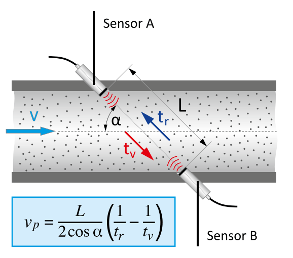
Fig. 1: Measuring principle of ultrasonic flow measurement
Piezoelectric ultrasonic sensors are used for flow measurement at SICK, on the basis of the ultrasonic transit time difference method. In this, ultrasonic signals are transmitted alternately through the exhaust gas flow at an angle.
Driving and braking effects due to the exhaust gas flow lead to different transit times of the signals through the flow of exhaust gas (Fig. 1).
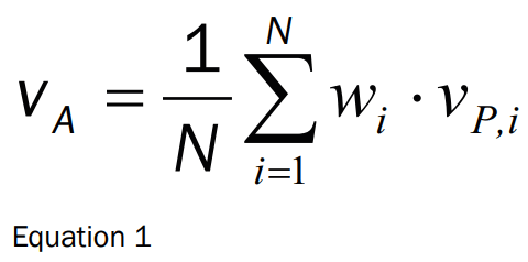
This difference in transit time is analysed by the integrated electronics and converted into a flow velocity along the ultrasonic measuring path. A representative area velocity can be determined using 4 ultrasonic measuring paths arranged across the flow cross-section (equation 1). The exhaust gas volume flow results from offsetting against the pipe cross-section at the measuring point.
Requirements
In recent years, the requirements for exhaust gas flow meters have increased in many ways, they involve real-time capability, a wide measuring range at high resolution, high temperature resistance, low pressure loss, low-maintenance operation and maximum measurement accuracy even under dynamic flow conditions, and very low flow rates.
The flow condition in the exhaust gas of internal combustion engines greatly depends on operating conditions and is subject to high dynamics. Pulsations arise during idling, as do highly turbulent flows and very low flow velocities.
Technological Approach
The exhaust gas velocity is measured in the measurement chamber of the instrument on four independent ultrasonic measuring paths, whose individual results are factored into the measurement result on a weighted basis. By using this 4-path arrangement, even disrupted flow profiles that result from less-than-ideal flow from the exhaust pipe can be accurately measured. The measuring
range, measurement accuracy, and repeatability can be seen in the table below (Fig. 2).
Fig. 2: Technical data (excerpt)
Measured variables
volumetric flow (actual), volumetric flow (normalised), gas velocity, speed of sound, gas temperature, gas pressure (barometric)
Measuring range (actual volumetric flow)
0..180 l/s [0..650 m³/h] as 2,5″ device
0..500 l/s [0..1800 m³/h] as 4″ device
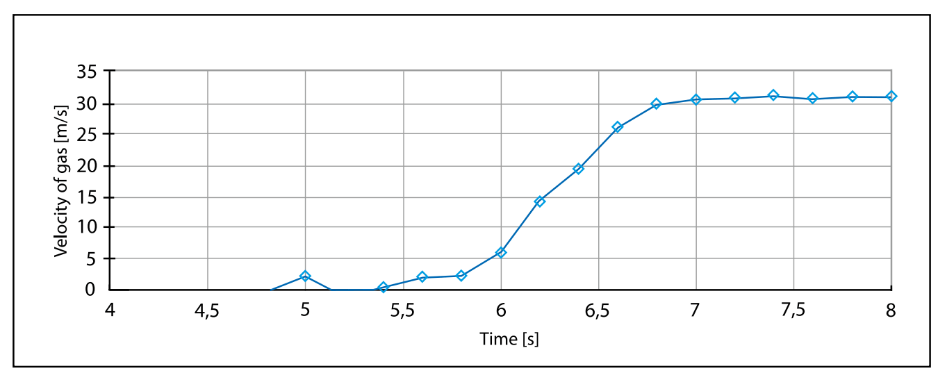
To reliably capture the dynamics of the exhaust gas flow and to achieve very high measurement accuracy in all areas, 50 time-offlight measurements are taken per second on each of the four measuring paths. This guarantees a solid base of data for signal evaluation without extending the response time of the instrument. Fig. 3 shows a typical step response.
The increase here is:
30 m/s². The T90 time is approx. 0.9 s.
Fig. 3: Flow measurement step response
The individual ultrasonic signals are sampled by the electronics in the MHz range, where a reliable transit time determination is achieved in the ± 5 ns range. This accuracy is particularly critical in the range of low flow velocities – when the engine is idling, for example – because the physical measuring effect is very small in this case. In addition, adaptive path compensation adjusts faulty measurements to individual paths under dynamic flow conditions and guarantees uninterrupted measurement even when the exhaust gas is strongly pulsating.
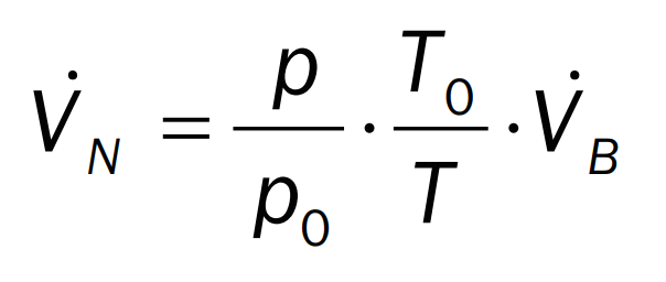
To achieve this, the ratio of the time-of-flight measurements between the individual measuring paths is acquired during uninterrupted measurement and compensated in the event of short-term signal interference. Another advantage of the measurement principle is its independence from the state-dependent speed of sound in the exhaust gas, enabling it to be largely independent of the composition of the exhaust gas, the temperature and the pressure. In addition to the operating volume flow, the measuring instrument also calculates the normalised flow rate through the integrated pressure and temperature measurement (equation 2).
Equation 2
Flow Conditioning
To further improve the metrological properties, innovative flow conditioning is used in the FLOWSIC150 Carflow to compensate for interrupted flow conditions. Based on experience, ideal inlet conditions are often difficult to achieve when installing the measuring instrument due to the confined spaces. In addition, variable flow pattern controls lead to different flow profiles. From the user’s perspective, the immunity of the instrument to flow perturbation is therefore of great importance – thus, the actual measurement of the flow velocity becomes independent of the specific flow conditions. Copper plates in the preheating section of the instrument cause flow rectification due to their location and support the occurrence of a flow profile that is as rotationally symmetrical as possible, with minimum pressure loss. In addition, they are welded to the heated pipe wall, whereby heat transfer is optimised for the inflowing exhaust gas. To keep the temperature gradients between the pipe wall and exhaust gas as small as possible and to prevent condensation, the entire measurement section of the instrument is heated throughout. This solution ensures uniform
temperature control of the exhaust gas over the entire pipe cross-section, with the result that the temperature measurement and subsequent normalization of the volume flow are carried out with considerably higher accuracy.
Sensor Cooling
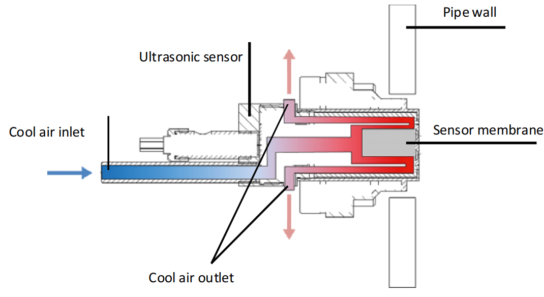
The piezoelectric materials in the ultrasonic sensors lose their piezoelectric properties above the Curie temperature (approx. 280 °C). Alternating thermal stress loads near the Curie temperature also lead to an increased aging effect on the materials. To enable the instrument to be applied at exhaust gas temperatures of up to 600 °C, patented sensor cooling with ambient air is used (Fig. 4). Thermal management of the ultrasonic sensors allows the sensor temperature to remain safely below the Curie temperature in the range of up to 600 °C, even when used continuously. In addition, the temperature fluctuations of the probes can be significantly reduced by cooling, which leads to significantly lower aging behaviour in the probes.
Fig. 4 Patented sensor cooling principle
Calibration
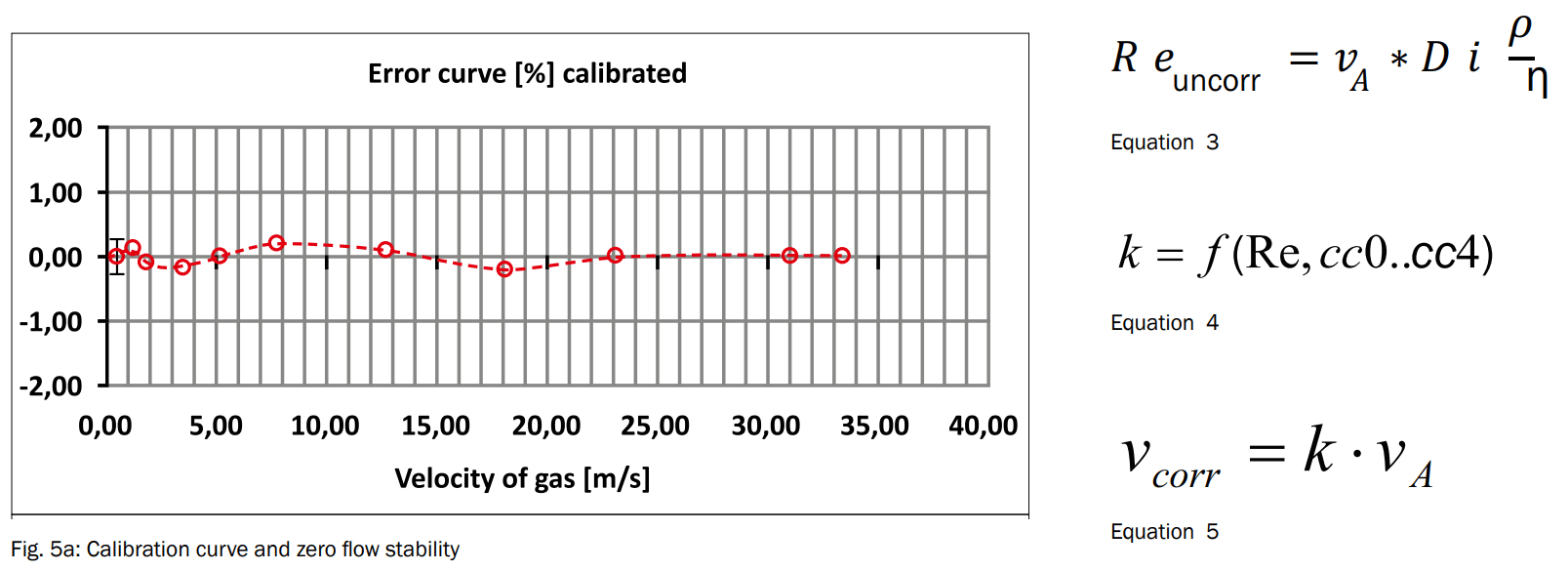
Each instrument is also calibrated to achieve the highest possible accuracy. To achieve this, the manufacturer uses certified test benches in accordance with the Measuring Instruments Directive, 2004/22/EC. Calibration is performed on the basis of the Reynolds number, using equation 3. For this purpose, the measuring instrument is installed on the test bench with a series connection to a calibrated ultrasonic gas flow meter with eight measuring paths.
By testing, the remaining variance from the measuring instrument and reference count is determined as an error curve and recorded using the Reynolds number. Subsequently, the error is corrected using a suitable polynomial, whose coefficients can be configured as parameters in the measuring instrument (equation 4). The correction factor is multiplied by the measured area velocity and thus leads to the corrected gas velocity (equation 5).
Figure 5a shows the results of this kind of calibration. In addition to the low residual error of max. ±0.3%, the reproducibility at <0.2% is assessed as very good.
Fig. 5a: Calibration curve and zero flow stability | Equation 5
Zero-Point Stability
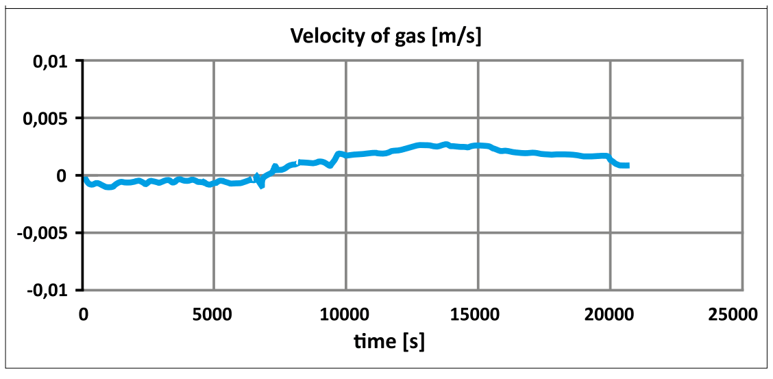
The accuracy of flow meters is primarily affected by the zero-point stability at low flow velocities. The minimum quantity range is also of particular interest for the exhaust gas measurement; for example, in the range near idling. For this reason, the gas velocity of a sealed measuring instrument was recorded over several hours. The results in Figure 5b show that stability is better than 5 mm/s. The results of zero-point testing with hot gas are in the same range.
Fig. 5b: Calibration curve and zero flow stability
Applications
Direct exhaust gas flow measurement has significant advantages over the alternative calculation of the exhaust gas volume flow from other measurands or model approaches. The measurement error increases when calculating from various measurands on the one hand – and on the other, model approaches are often limited to specific system environments.
Therefore, measurement of the exhaust gas flow rate represents the simplest, most accurate method and is used in various applications.
Discrete emissions curves
Direct exhaust gas flow measurement allows allocation of pollutant concentrations from exhaust gas analyses to the actual exhaust gas volume flow with no time-consuming dead time correction. If the exhaust gas volume flow corrected to standard conditions is used, the emission densities known under standard conditions are used to calculate mass-related emissions (equation 6). The result is the time curve of the quantity of pollutants.
Representative pollutant emissions corresponding to the bag results from CVS systems on chassis dynamometer test benches result from the accumulation of the measured values (equation 7). This method can also be used on engine test benches to determine discrete pollutant curves and thus allows early and very accurate determination of the anticipated CVS measurement results.
Bag Mini-Diluter
In addition to the CVS methodology, the Bag Mini-Diluter has been certified in the USA by the EPA since 2002. [1] With this measurement method, vehicle emissions are diluted with synthetic air and directed to the exhaust gas bag proportionately in relation to the exhaust gas volume flow. The exhaust gas volume flow of the vehicle is required in real time as a performance indicator for the mass flow controller for sampling. Various test results confirm that the volume measurement of exhaust gases by ultrasound is very well suited to this method. [2], [3]
Gas Flow Measurement | SICK FLOWSIC150 Carflow
Summary
Flow measurement using ultrasound is ideally suited to meeting the diverse requirements of exhaust gas flow measurement in test bench applications.
The measurement results produced by the FLOWSIC150 Carflow demonstrate a very level of high measurement accuracy with a very short response time. Measures in the area of flow conditioning and the use of state-of-the-art sensor technology in the 4-path design are making it possible to optimize independence from the flow pattern control, zero-point stability, and small quantity measurement.
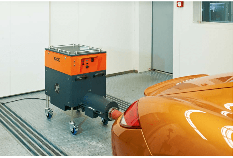
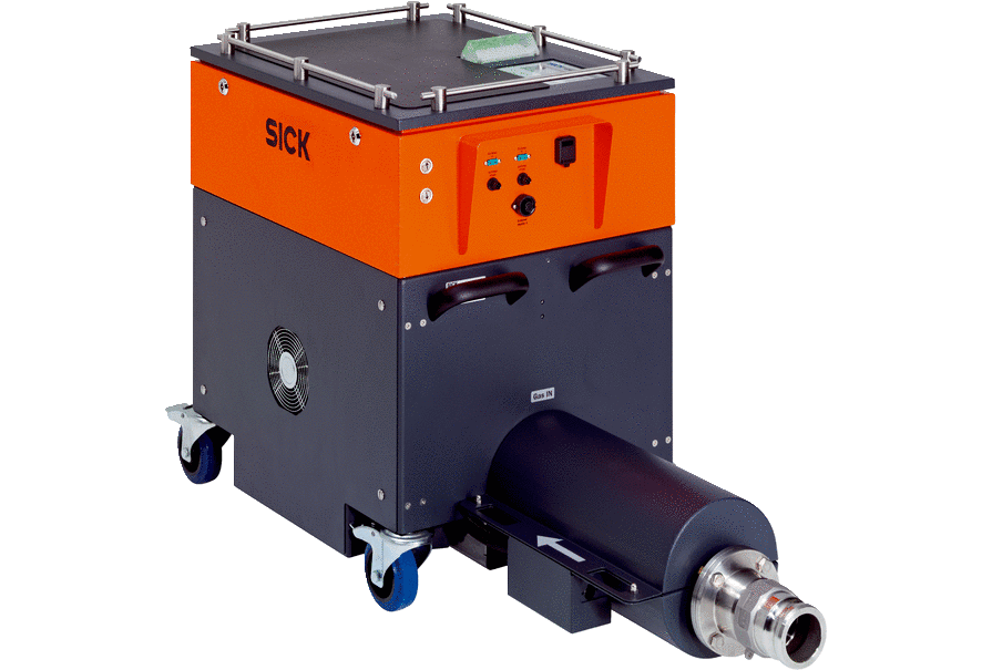
The patented sensor cooling enables the instrument to be used at exhaust gas temperatures of up to 600 °C, and at the same time ensures the ultrasonic sensors achieve a long service life through optimum thermal management. The FLOWSIC150 Carflow is available as a mobile dynamometer wagon in a compact design and is ideally suited to flexible exhaust gas flow measurement on exhaust gas and chassis dynamometer test benches.
Equations
vA Mean area velocity
vP Mean path velocity
N Number of measuring paths
wi Weighting factor of a measuring path
VN Standard flow
VB Operating flow
p Pressure
T Temperature
p0 Standard pressure
T0 Standard temperature
Re Reynolds number
k Correction factor
cc0–cc4 Polynomial coefficients
ρ Exhaust gas density
η Dynamic viscosity
Bibliography:
[1] United States Environmental Protection Agency, “ Dear Manufacturer letter CCD-01-23”, December 6, 2001.
[2] Guenther, M.; Vaillancourt, M.; Polster, M.: Advancements in Exhaust Flow Measurement Technology. SAE Technical Paper 2003-01-0780, 2003
[3] Yassine, M., Kirchoff, C., Laymac, T., Berndt, R. et al., „Improving Direct Vehicle Exhaust Flow Measurement“, SAE Technical Paper 2005-01-0686, 2005, doi:10.4271/2005-01-0686.
ELECTRICAL & PROCESS INSTRUMENTATION EQUIPMENT
FOR EXPLOSIVE ATMOSPHERES & Hazardous Areas
Thorne & Derrick are Specialist Distributors of Hazardous Area & Explosion Proof Equipment with IECEx & ATEX Certifications to the onshore and offshore oil, gas, petrochemicals and process industries.
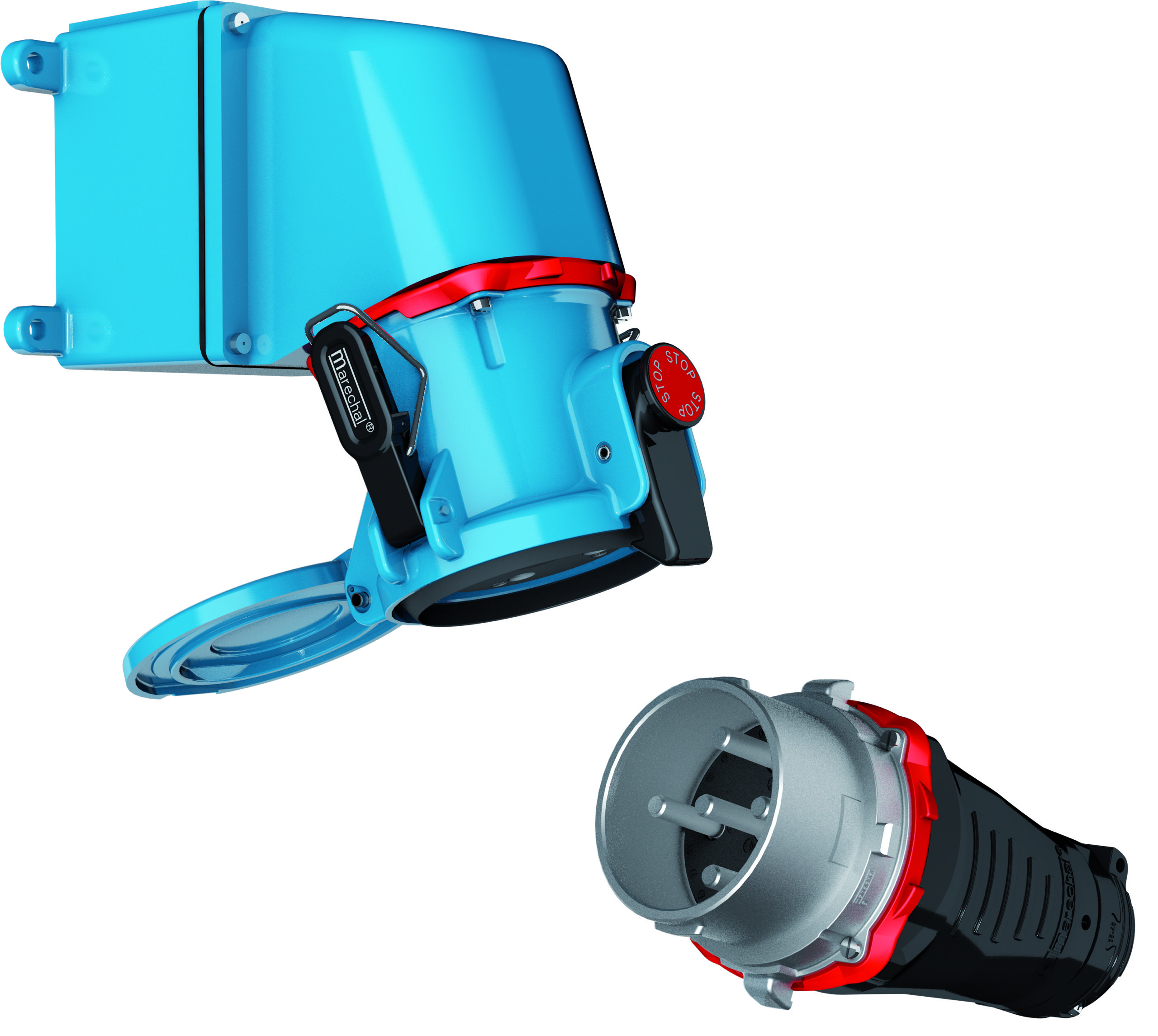
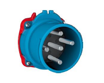
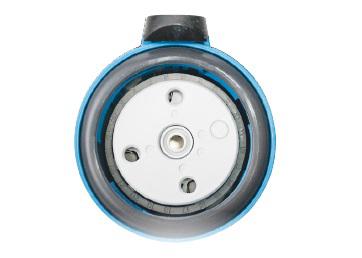
Electrical plugs and socket-outlets in the Marechal DECONTACTOR™ range are sized from 30A to 400A. The DS range with integrated switch is the widest and most comprehensive DECONTACTOR™ range. Both sockets and inlets are available in metal version from 90A rating. It offers numerous mounting options (boxes, handles and sleeves).
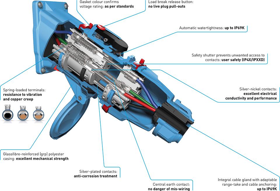
Marechal DS plugs & sockets have an incorporated breaking capacity of AC-22 / AC-23 and have either an impact resistant GRP or metal casing. The DS9 also features a safety shutter, silver-nickel butt contacts and metallic braid to comply with international standards.
With a single base (e.g.: 3 Pnt – 230/400 V) it is possible to feed 3 plugs indifferently:
a 3 Pnt – 230/400 V plug
a 3 Pnt – 400 V plug
a Pnt – 230/400 V plug
This compatibility provides real savings on the installation of these sockets for the user.
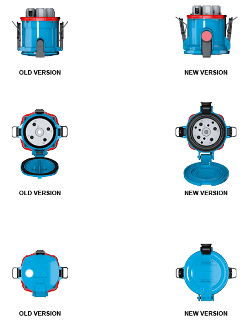
Main Changes to the Marechal DS9
Design changes with integrated closing mechanism of the socket, increased robustness, easier connection and increased wall thickness to the casing.
Improved impact resistance (IK10).
Addition of a silicon gasket giving IP66/67 watertightness with closed lid or with inlet/socket connected.
Modification of locking pawl system with an improved robustness
Still compatible with previous DS9 versions – No additional kits required
180º lid opening & larger STOP latch button, which were optional on the older model, are now featured as standard (Please note that the self-returning lid option (R) becomes a 180° returning lid instead of 120°)
Marechal DS9 Improvements
Marechal DS Decontactor
Features
Butt Contact on a Silver-Nickel Tip
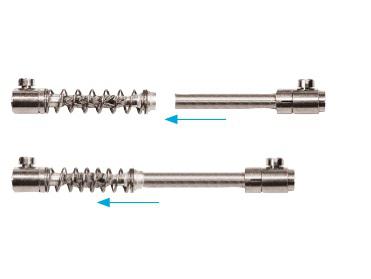
The Marechal DECONTACTOR™ and connectors are all fitted with butt contacts with silver-nickel tips. They provide exceptional connection quality by eliminating the damage due to electric arcs and to wear seen with pin and sleeve sockets. The silver is an excellent conductor of current even when oxidized. Conductivity is optimal even in the presence of vibration and temperature variation thanks to the pressure of the springs.
Crimped Braids
The Marechal contact uses a crimped braid with a spring which provides contact performance and tolerances superior to pin and sleeve contacts. The flexibility of the braid and the spring allows the base contact tip to always be perfectly aligned with the plug contact tip. These contacts, which are silver and anti-corrosion treated, offer very good corrosion resistance.
Elastic Lock Terminals
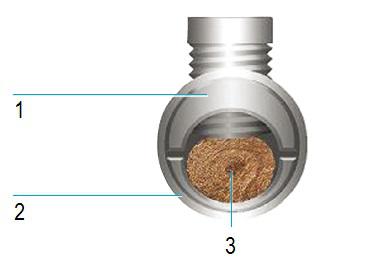
Marechal contacts are fitted with “elastic lock” connection terminals.
The wire clamp is split and surrounded by a rubber ring. This method allows the tightening force on the wire to be constant. Hence despite the creep of the copper or aluminium, the variations of temperature and vibration, the conductor wire is perfectly connected to the contact terminal.
Safety Shutter
DECONTACTOR™ bases are fitted with an interlocked safety shutter which prevents access to live contacts. This shutter only unlocks at the time of connection of the plug into its base. The Marechal range connectors and DECONTACTORs™ have casings made from fibre glass- or metal-reinforced GRP, depending on the models. This choice of material contributes to the excellent mechanical performance and longevity of the socket.
Marechal DS Decontactor
Benefits
These technical choices provide Marechal connectors and DECONTACTORs™ with unparalleled levels of performance:
Absolute safety, even after thousands of connections/disconnections,
The ability to withstand repeated overloads, particularly on power supplies to motors with frequent starting,
Perfect operation in the presence of vibration and variations in temperatures,
Resistance to shocks, falls and climatic variations,
A perfect resistance to corrosion and the most severe chemical agents.
The quality of the material, the design, the assembly and the inspection of each component are at the core of Marechal’s know-how and technology.
Each component provides a precise function that optimizes the performance, safety and sustainability of our sockets and installations.
Marechal DS Range – Bursting with features to ensure user safety
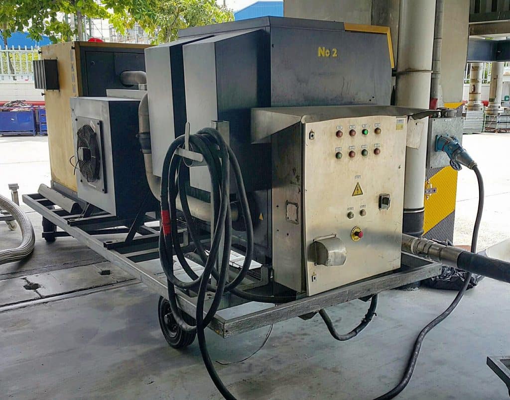
Marechal DS9 Plugs used for Blower Fan Connections
150amp Marechal DS9 plug connectors provide safe and reliable LV power.
This Article was originally published by FSM (Fire & Security Matters) in March 2020, The Independent Voice for Security & Risk Professionals
Hazardous Areas &
Explosive Atmospheres
The parent company of Swindon-based Oak Furniture Land has been fined nearly £400,000 for failing to protect its employees from hazardous and explosive atmosphere conditions at its premises in Cheney Manor Industrial Estate.
JB Global, which owns the furniture company, pleaded guilty to significant breaches of the Dangerous Substances and Explosive Atmosphere Regulations (DSEAR) and the Control of Substances Hazardous to Health (COSHH) following a prosecution by Swindon Borough Council. Sitting at Aldershot Magistrates’ Court, Judge Pattinson ordered the company to pay fines totalling £398,000 and costs of £94,904.
Investigations into various health and safety breaches at the company began in 2016 following a complaint by a member of staff. After visiting the business, the Council’s Health Compliance Team was alerted to the fact the company was preparing room divider sheets, which was not a registered activity at the warehouse.
Evidence showed the preparation of the sheets was carried out in a highly explosive environment and not enough action was taken to mitigate the risks to employees.
Workers were provided with damaged or faulty facemasks and conditions were so bad, council officers served an immediate Prohibition Notice.
JB Global was prosecuted for failing to prevent/control exposure of employees to solvents and wood dust under DSEAR as well as failing to to carry out risk assessments and of failing to prevent exposure to substances hazardous to health under COSHH.
Two further charges were brought against the company for failing to ensure the safety of its employees, while a further charge of failing to ensure the safety of agency staff or contractors was also levied against the firm.
Councillor Cathy Martyn, Swindon Borough Council’s Cabinet Member for Housing and Public Safety, said: “This prosecution and subsequent penalty highlights the importance of taking steps to protect the health and safety of employees and members of the public.
“The uncontrolled work activities being carried at the Cheney Manor site posed a very real risk of explosion, fire and potential long-term health conditions resulting from exposure to carcinogenic MDF dust and harmful chemicals
“The investigation also covered numerous manual handling accidents and work-place transport incidents, which resulted in injuries to employees.
“We take breaches of health and safety laws extremely seriously and I would like to praise the diligence of our Health Compliance Team for carrying out this complex investigation and highlighting this extremely bad practice. I hope it serves as a reminder to all businesses of the need to put the health and safety of their employees at the forefront of their activities.”
EXPERTS IN EQUIPMENT FOR EXPLOSIVE ATMOSPHERES
Thorne & Derrick are leaders in the development and distribution of Product Innovations that deliver significant improvements to clients plant, people and operational safety in the explosive atmosphere industries.
Your proactive problem solvers experienced in succession planning for the replacement of obsolete, non-conformant and legacy equipment in hazardous areas.
Your first-choice provider of innovative and competitive solutions to ensure ATEX & IECEx Compliance for Hazardous Area Electrical, HVAC & Process Instrumentation Equipmentto UK and international projects.
EXHEAT Heaters | Distributed from Stock | International Delivery | Competitive Prices | Contact Us Today
Offshore Well Testing
This Case Application for “The Bulldog” electric heater, which is manufactured by EXHEAT and is stocked and distributed exclusively in the UK by Thorne & Derrick, focuses on a recent application where the client required a winterisation solution to weatherise air compressors situated in a Hazardous Area.The client provides products and services to the well testing sector, and relies on air compressors to keep critical systems operational in explosive atmospheres where an accumulation of flammable gas or vapour which, when mixed with air, has the potential to catch fire or explode.
Industry Sector| Offshore Well Testing
Hazardous Areas & Explosive Atmospheres
Electrical Heater Application & Benefits | The portable electric fan heaters with ATEX Certification were selected after careful competitor evaluation to provide a winterisation / weatherising solution for two air compressors used in vital offshore well testing.
The portable heaters were purchased and supplied to the UK’s leading provider of air compressors, steam generators, rig cooling equipment and qualified personnel to weatherise air compressors for the well testing market sector worldwide.
These air compressors were specifically dedicated to well testing applications; in both onshore and offshore hazardous areas and explosive atmospheres. The majority of today’s well test burners rely on compressed air as the propellant to provide the energy to atomise the well fluid in preparation for combustion.
Weatherise Air Compressors
Given the risk posed while working in a hazardous area, it was paramount that the essential Zone 2 air compressors were maintained correctly in order to continue to provide safety to operating personnel along with reliability and to enable productivity.
A common threat posed to the safe operation of systems in hazardous areas is winterisation. Air compressors, which are used in vital applications including well testing, can be greatly affected by the impacts of winter and freezing temperatures.
The following guide on air compressor best practices, focuses on important steps to avoid the significant impacts of winterisation on air compressors.
Temperature:No industrial air compressor should be operating in temperatures below 40 degrees Fahrenheit, and it is recommended to keep your compressor room around or above 45 degrees during the winter.
Room Heating: You simply need enough heat energy inside of the room to keep the room above freezing when the compressor is not in operation.
Minimise Energy Losses: While optimizing the productivity, energy efficiency, and durability of your compressed air system throughout the winter, ensure system operators weatherise it.
An air compressor needs to be prepared for winterisation to maintain its reliability and performance. Some units are prohibited from starting if the temperature of the atmosphere is below freezing. Keeping an air compressor warm prevents cold starts, which can cause wear and tear on the motor, and in some cases, lead to catastrophic failure. The Bulldog electrical heater, supplied by Thorne & Derrick, was carefully selected to mitigate the discussed issues and to enable the continuation of a safe and productive hazardous area environment.
EXHEAT MFH
The client required a heater certified by ATEX for safe use in hazardous areas to heat up the room from -40°C to a target temperature of 0°C. Following a heat loss calculation provided by Thorne & Derrick, we concluded that two electric heaters totalling 12kW output would heat up the required area in just under 40 minutes.
We provided the solution to the client of the EXHEAT MFH, 6-230 model, which is ATEX & IECEx certified, and offers Ingress protection of IP65. The MFH heater (“Bulldog”) is constructed with polyamide PA66 with glass and steel fibre reinforcement.
T Class Rating T3
ClassifiedHazardous Area Zone 1/2 (IIB) or Zone 21/22 (IIIC)
Nominal Heat Output 6kW
ManufacturerEXHEAT | Heater Range MFH The Bulldog | Heater Model MFH-6-230
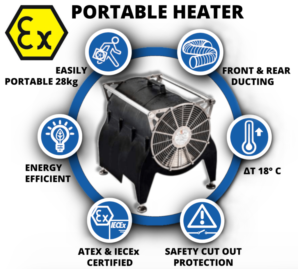
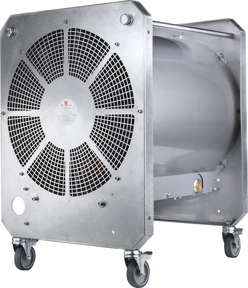
The MFH Portable Fan Heater manufactured by EXHEAT and Distributed Exclusively in the UK by Thorne & Derrick is the world’s first truly portable fan assisted heater with dual hazardous area ATEX & IECEX Certification. The portable heater has been extensively adopted by the process and hazardous area industries to safely provide temporary and portable air warming to workplaces in potentially explosive atmospheres.
LEADERS IN ATEX INNOVATION TO THE HAZARDOUS AREA INDUSTRIES
Thorne & Derrick are leaders in the development and distribution of Product Innovations that deliver significant improvements to clients plant, people and operational safety in the explosive atmosphere industries.
Your proactive problem solvers experienced in succession planning for the replacement of obsolete, non-conformant and legacy equipment in hazardous areas.
Your first-choice provider of innovative and competitive solutions to ensure ATEX & IECEx Compliance for Hazardous Area Electrical, HVAC & Process Instrumentation Equipment to UK and international projects.
Press Release Date: 02.04.2020 uploaded by Chris Dodds (T&D Sales + Marketing Manager) World’s First Fully Certified ATEX Doors Thorne & Derrick International, the Experts in Equipment for Explosive Atmospheres, today announce the signing of a Commercial Distribution Agreement...
Press Release Date: 04.07.2019 uploaded by Chris Dodds (T&D Sales + Marketing Manager) Category: Stockist Distributor Agreement Announcement Thorne & Derrick International announce that they have signed a Preferred Distributor Agreement with Raytec, the world leading manufacturer of LED...