EAC Lighting
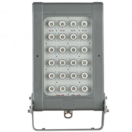
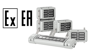
Raytec SPARATN Flood & Bulkhead
EAC Certified Hazardous Area Lighting
Did you know Raytec Spartan Ex lighting products are also EAC Certified and approved so can be used in the Russian market?
Raytec’s SPARTAN range of LED lighting for hazardous areas has been credited with EAC Russian Certification, widening the global approval of SPARTAN luminaires and lighting products for explosive atmospheres to provide new opportunities for business growth in new markets.
EAC
EAC is the Mark of Conformity for Customs Unions (CU) Countries – the GOST safety mark has been replaced by this new conformity mark called the EurAsian Conformity Mark or EAC.

EurAsian Conformity Mark (EAC)
The EAC declaration and the EAC certificate in conformity with the technical regulations TR CU of the Eurasian Economic Union are EAC Certification documents issued by independent accredited certification bodies.
Such organisations perform their function through laboratories accredited to the public agencies in charge of the supervision of metrology and standardisation in the the countries of the EAC Economic Union.
➡ Thorne & Derrick are Specialist Distributors of Hazardous Area & Explosion Proof Equipment with EAC Certifications to international projects through our Exports Division.
Working closely with clients and our supply chain we can assess the condition and degradation of your hazardous area installations and implement EAC conformant specifications to manage the planned replacement of legacy equipment with international classifications including EAC, ATEX and IECEx.
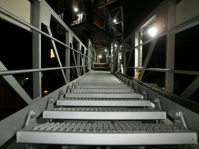
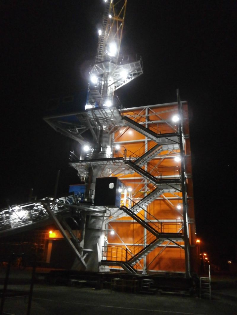
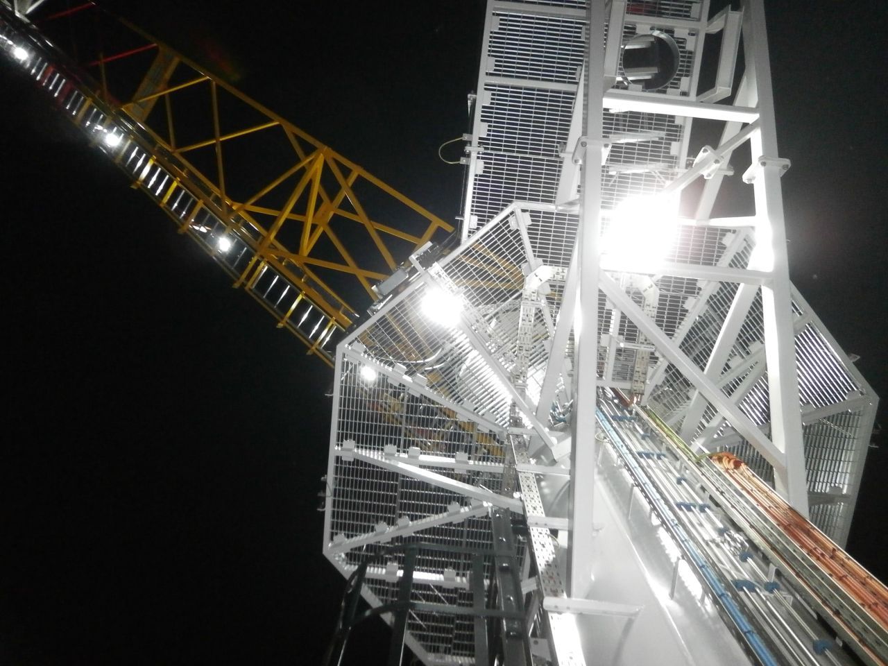
Below are examples of an installation on a crane destined for Russia for the Yamal LNG project.
Raytec SPARTAN Flood and SPARTAN Bulkhead products were used for general illumination throughout the crane and access areas, providing enough light for the safety of the workers.
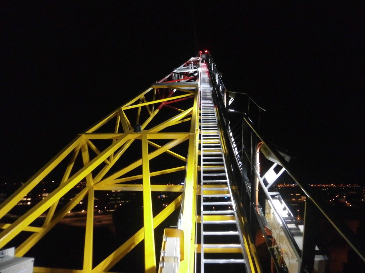
Raytec SPARTAN range installed on a crane
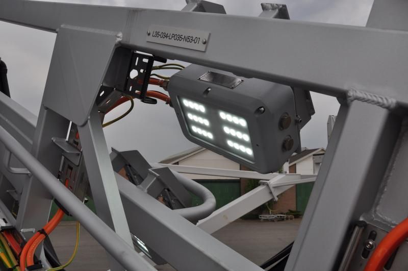
Raytec SPARTAN Bulkhead in situ
EAC Certified Lighting For The Russian Market
Hazardous Area Lighting
EAC Lighting
💡 Did you Know? Thorne & Derrick using latest software provide a FREE LIGHTING DESIGN SERVICE for the specification and supply of ATEX & IECEx Certified light fittings to provide safe and reliable lighting in explosive atmospheres and hazardous area locations.

Raytec | Hazardous Area Lighting EAC Approved & Certified
SPARTAN is a full range of Ex LED luminaires and lighting approved for all ATEX and IEC Ex Zone 1 and Zone 2 hazardous area environments, including UL /CSA C1D2 installations. The hazardous area lighting products are designed for the most extreme environments – Flood, Linear, Bulkhead, Bay and Crane luminaires with emergency and industrial lighting versions are also available from Thorne & Derrick International.

EAC Lighting & Hazardous Area Electrical Equipment | Thorne & Derrick International, based in the UK, are the leading supplier of EAC Approved Lighting for safe and reliable installation in hazardous areas and locations – this includes Lighting for hazardous areas certified by the EAC for use in potentially explosive atmospheres in both onshore and offshore locations.
 Contact Thorne & Derrick Sales Team for the complete range of ATEX Lights manufactured by Raytec.

More Hazardous Area Lighting Blogs
EXPERTS IN EQUIPMENT FOR EXPLOSIVE ATMOSPHERES
leaders in ATEX Innovation To The Hazardous Area Industries
Thorne & Derrick are leaders in the development and distribution of Product Innovations that deliver significant improvements to clients plant, people and operational safety in the explosive atmosphere industries.
Your proactive problem solvers experienced in succession planning for the replacement of obsolete, non-conformant and legacy equipment in hazardous areas.
Your first-choice provider of innovative and competitive solutions to ensure ATEX & IECEx Compliance for Hazardous Area Electrical, HVAC & Process Instrumentation Equipment to UK and international projects.

Follow our Showcase Page on LinkedIn to receive hazardous area product innovations, industry news, whitepapers, videos, technical tips and training webinars for professionals involved in the explosive atmosphere industries.

Explosive Atmospheres
The following paper has been republished with the kind permission of Alex Brady from Expo Technologies.
With more than 60 years’ experience and deep knowledge of hazardous area zones and standards, Expo Technologies develops and delivers simple, robust, certified solutions that improve safety and save customers time and cost.
Expo works with end-users, integrators and OEMs across a wide range of explosive atmosphere industries, including oil & gas, chemical & petrochemical, pharmaceutical & biotechnology and power generation.
ROOMS IN HAZARDOUS AREAS
GLOBAL COMPLIANCE
Abstract – This paper reviews the current legislation for certifying rooms in hazardous areas with the following aims: to describe the major aspects of certifying rooms for use in the international marketplace and establish the appropriate body for this assessment. This is achieved by reviewing the current status of the International Electrical Commission, its member states and the progress made towards being incorporated into national legislation. The International Electrical Commission standard is analysed to determine the suitability of the protection concepts and to consider how it reflects current market practices; The harmonised European Standard for Transportable Ventilated Rooms, The North American Fire Protection Association and Det Norske Veritas’ standards for off-shore containers are all considered. The discussed differences aim to guide designers in the standards application and how to achieve global compliance.
Index Terms — IEC, Hazardous Area, Explosive Atmospheres, Compliance, Pressurized Room, Pressurization System, Safety Standards, Classification Societies.

Hazardous Area Rooms Introduction
Equipment located inside hazardous area locations must be protected by suitable methods to limit the risk of an explosion.
Protection can be applied to each individual system, but this can lead to complex and expensive equipment specifications for a system. Alternatively, the room in which this equipment is mounted, whether a Remote Instrument Building or a staff rest area, can be positively pressurized ensuring the exclusion of a hazardous environment.
The IEC is becoming a widely accepted body throughout the world with many of the standards already harmonised to local directives. There are however many discrepancies between it and the current legislation. Certain countries, either due to their national skill set or industry, have developed a preference for one style of protection. To illustrate this, consider cable terminal boxes. America tends to favour Explosion Proof concepts (Ex d) while Europeans would use Increased Safety (Ex e); Both are acceptable and safe if installed correctly, yet resistance may be found if the designer applies them in the incorrect market. An explanation may be that industries operating Hazardous Areas are primarily involved in the reduction of risk; Removal of the unknown factor caused by an unfamiliar protection concept goes some way to achieving this. There are, however, also the commercial aspects to consider and these standards serve as powerful barriers to trade.
Consider the example above; if the US market demanded the much cheaper and lighter Ex e enclosures for cable termination, an industry worth several million Dollars a year and associated manufactures, would be facing a significant shift in the product requirements and it may not be one they could accommodate. Designing for the international marketplace requires consideration of these aspects and awareness that more than one protection concept could be applied; the one selected will need to be accepted universally.
The paper outlines the concept of protecting rooms with this in mind by describing the current best practice and highlighting changes that need to be considered. The discrepancies are then examined with respect to safety implications and what is practicable in industry. The safety analysis is drawn from the author’s knowledge in the certification field and selected Notified Bodies while the practicalities have been researched with major manufacturers of remote ventilated rooms for use in the on- and off-shore environments. The paper is structured to follow IEC 60079-13 [1] main chapters and will assess whether 60079-13 is sufficient to protect rooms or if other considerations will need to be made.
Protection for internal source of release in safe area pv is dealt with by positive pressurization in IEC while EN uses negative pressure in the Room to contain the hazard. Further variations are made to definitions of containment systems and the assessment of infallible equipment. This will not be covered in this paper but should be read in IEC60079-13 cl 10 & 11 / EN50381 [2] cl 7 & 11 and IEC 60079-16 [3].
Hazardous Area Zones
DEFINITION OF TERMS
The IEC nomenclature is as per the ATEX95 (94/5/C) directive. The terms are described below and where applicable cross referenced to the NFPA equivalent.
1) Zone 1: Explosive atmosphere is likely to occur in normal operation occasionally (10>1000 hrs / year). This is similar to NEC Division 1
2) Zone 2: Explosive atmosphere is unlikely to occur in normal operation or infrequently (<10 hrs / year). This is similar to NEC Division 2
3) EPL: Traditionally zoning only considered the probability of explosion. Equipment Protection Levels were introduced under the IEC standards to take in to account the potential risk of the component creating an explosion. For Group II (above ground) applications the first letter indicates the nature of the hazard being either Gas or Dust and the second letter shown in lower case indicates the risk of. Therefore Ga- is equipment suitable for explosive gas atmosphere having a very high level of protection, Gb2 has a high level of protection and Gc- has an enhanced level of protection.
4) Pressurization Concepts: Pressurization protection falls into four categories depending on the application and level of explosion protection required. The equivalent is shown for the current EN standard but is only for indication of the zone and not an indication of the protection concepts employed.
“pv”- maintains adequate dilution to any abnormal internal source of release to reduce the EPL to none. Equivalent to EN50381 type v4
“px”- pressurization and dilution to reduce EPL of Gb to none. Equivalent to EN50381 type v2
“py”- pressurization and dilution to reduce EPL of Gb to Gc. No equivalent to EN50381.
“pz”- pressurization and dilution to reduce EPL of Gc to none. Equivalent to EN50381 type v3
REVIEW OF CURRENT PRACTICE In HAzardous Areas
A. Defining a Hazardous Area Standard and its Application
The following statement has been taken from the IEC website and the relevant sections truncated for clarity:
“An International Standard is a document, established by consensus and approved by a recognized body, that provides, for common and repeated use, rules, guidelines or characteristics for activities or their results”…”A normative document, developed according to consensus procedures, which has been approved by the IEC National Committee members of the responsible committee”. . . ”Any member of the IEC may participate in the preparatory work of an International Standard, and any international, governmental and non-governmental organization liaising with the IEC also participates in this preparation”. . . “it can be submitted to public enquiry in any country. Thus, through the democratic tools of consensus and public enquiry, any interested party may speak up and have their say in the development and publication of an international standard”…”Adoption of IEC standards by any country, whether it is a member of the Commission or not, is entirely voluntary.”
So, what value does an international standard have if it is recognised by many in the industry, but its application is entirely voluntary? It is not until the standard has been incorporated into the local law that it is of any significant use to manufactures supplying into that area. In the European Community (EC) the central body issues Directives which give guidelines to the EC states who in turn issue regulations in the form of standards which are said to be harmonised to the governing Directive. In the USA the architecture is described by the National Fire Protection Association (NFPA) together with the National Electrical Code (NEC) [4] and, although there is a mutual agreement between the US and Canada allowing all notified bodies to certify to the relevant standard, they too have a set of regulations under the Canadian Electrical Code, (CEC) [5]. This structure is fairly typical worldwide with each economic area needing to be reviewed in accordance with its local laws and practices.
Include the fact that this is a commercial world and the organisations providing the financial backing have a vested interest in how their assets are protected, and yet another layer of complexity is added. Some economic areas have preferred notified bodies such as Factory Mutual (FM) and Underwriters Laboratories (UL) in North America or Det Norske Veritas (DNV) operating in Europe and the North Sea; These may also issue additional guidelines in areas where it is felt the risk is not adequately covered by local laws.
In 1995 DNV issued the standard 2.7-2 [6] to provide an engineering standard for the certification of rooms as no European standard existed. When in 2004 the European standard was issued it seems that this was largely ignored, and most major players still work to the DNV code. This is the exception rather than the rule for industry but is an indication of commercial power that is exhibited when product specification changes may negatively impact organisations operating in the market.
B. Recognising When to Apply the IEC Standard
The benefit of a single governing standard becomes clear but raises the problem of how to discover if the IEC standard is the best one to adopt for a specific project or product development specification. The IEC publishes a list on its website of the thirty member states, however not all IEC standards have been harmonised under the specific states’ directives for hazardous areas.
There is currently no single document outlining the acceptance of 60079-13 at the national level due to its recent issue. Table 1 shows the adoption of 60079-0 General Requirements 5th Edition 2007[7]. Although indicative of the scope of acceptance, the designer must bear in mind that this can vary from one issue of a standard to another as well as across the range of standards included under the 60079 umbrella. [10]
The following key refers to the table below:
1-Indicates Adoption without National Difference
2- Indicates Adoption with National Difference
3-To be Advised
4- Not Recognised
ADOPTION OF 60079-0 BY MEMBER STATES
| Member States |
Adoption Status |
Member States |
Adoption Status |
| Australia |
1 |
Slovenia |
2 |
| Brazil |
1 |
Sweden |
2 |
| Canada |
2 |
United Kingdom |
2 |
| China |
2 |
India |
4 |
| Croatia |
2 |
Japan |
1 |
| Czech Republic |
2 |
S Korea |
3 |
| Denmark |
2 |
Malaysia |
4 |
| Finland |
2 |
New Zealand |
1 |
| France |
2 |
Norway |
2 |
| Germany |
2 |
Russia |
2 |
| Hungary |
2 |
Singapore |
1 |
| Italy |
2 |
South Africa |
1 |
| Netherlands |
2 |
Switzerland |
2 |
| Poland |
2 |
Turkey |
3 |
| Romania |
2 |
USA |
3 |
C: Hazardous Area Standards Being Applied in Industry
Review of current practices showed that the North Sea oil fields were complying primarily with DNV standards. Although some manufacturers had done an assessment to EN they were not certifying accordance with this. This aligns with the fact that the selected Notified Body in this region was generally DNV’s verification and classification departments. North America is dominated by products that are approved to NFPA 496 [8]. The pressurized room market is well defined in this region. Many competitors supply certified or assessed components that can be added to the pressurized room and simplify the certification process for the room manufacturer.
On-shore Europe is now emerging from a period in which there was no specific cover for fixed installation rooms. Many manufacturers therefore adopted parts of the EN standard, parts of IEC 60079-2 [9] and, if reviewing analyser houses, 60079-16 [3]. Many could then argue that the market did supply a certified pressurization system and so the in-house solution would be considered as part of the entire application certificate. The IEC publication therefore meets the need for room manufacturers to simplify the certification process, much as it is in North America.
To ensure worldwide compliance the pressurization system, installation and the room construction needs to be compliant with all the major regulating standards. The emphasis here is on ensuring the protection concepts employed are robustly reviewed and, as systems are working together, on minimising the risk while ensuring that they do not unnecessarily constrain innovation in the product design or reduce commercial viability.
60079-13 however, is considered to be an installation standard rather than a product standard due to the nature of the fixed installation of the rooms it refers to. However, manufacturers in the field still require their components to be suitable for installation to this code.
ANALYSIS OF Hazardous Area STANDARDS
A. Constructional Requirements For Rooms in Hazardous Areas
Many constraints exist for the construction of rooms but those
examined below will refer, predominantly, to either enabling
pressurization or safety systems required to meet the standards.
1) Doors: There is no requirement in IEC to provide locks on the doors for normal use to limit access, however, lockable doors still need to have panic bars inside. Doors not used as primary means of ingress or egress may be omitted from outward velocity calculations if either of the following applies: They are marked as “Restricted Access” and used less than three times per day for no longer than 60s each time, with alarm at constantly manned location on being opened. Or used only for the infrequent movement of equipment, marked again as “Restricted Access” and under management control secured on the closed position. This allows room designers to meet the practicalities of installing large components through double doors without overburdening the requirements of the Room Pressurization system or the additional cost and complexity of large airlocks.
2) Switches: Switches are recognised for use with Purge system but not a requirement when using the minimum outward velocity of air concept. However, if an airlock is used it is no longer possible to employ the outward velocity methodology and switches will be required. Switches are useful regardless of specific requirements as means of determining the door status. This is particularly useful in a Zone 1 environment where you may avoid having to restart if it is temporarily halted due to pressure loss and a door switch indicates an open door. The timer must then only be stopped and restarted on return of pressure and flow. This state may persist for 60 seconds before the timer must be reset.
3) Door Closing: IEC also has a clause which in practices may be difficult to implement. It states that doors must be capable of closing against the normal operating pressure of the room. This in itself is not impossible although it does require a fairly heavy door spring / gas lift. If the outward velocity concept is employed this becomes less useful due to the nature of fan curves. As the pressurization system goes into the high flow mode and the flow is restricted by the closing of the door the pressure increases along the fan curve and may be several times greater than the normal operating pressure. One solution is to use a two stage closer first closing the door sufficiently to allow the system to return to its normal state and the second then closing against the normal pressure. It is not possible to hinge the doors to allow the pressure to close the doors as all the standards specify that doors must open outwards.
4) IP Rating: IEC 60079-13 defines the room as needing to be capable of maintaining a pressurized state where EN requires rooms to be at least IP40. In practice the room should be IP5X in order not to limit the capability of the Pressurization system in overcoming excessive leaks. Another important factor to consider in warmer climates is the additional heat loading that the pressurization system puts on the HVAC of the room. Rooms with high leak rates may struggle to maintain the specified temperature and humidity specifications. In the worst of the case studies excessive room leakage caused the dehumidifier drips trays to flood resulting in water droplets being circulated in a remote instrument building.
5) Mechanical Strength: IEC 60079 and EN 50381 require over pressure tests of either: 1.5 times maximum operating pressure or, as per IEC, only the maximum pressure achievable by the system. The latter reduction in test criteria is reasonable considering the defined characteristics that fan driven pressurization systems will have. IEC also lists the requirements of an impact test using a 25mm diameter sphere striking any part of the room with 10 Joules of energy. The test requirement is for the part not to sustain any damage that may cause the differential pressure to drop below 25Pa. This has particular implications for structures such as windows. The construction requirements in DNV are more onerous, covered under 2.7.1, and are based on the in service expectations of mobile rooms being hoisted on to platforms.
6) Inlets & Ducting: IEC recommends the location of inlets and outlets are arranged so as to aid the distribution of the purge gas while having considered the density of the hazardous gases being dispersed. Normal practice is to locate the inlet and outlet at diagonally opposite ends of the room. Dispersion of lighter than air gases require a high outlet location while the denser than air gases would have it at floor level. If there are false floors or cable runs these must be considered for their ability to trap gases. Where a mixture of light and heavy gases may be present it is good practice to place the exit at low level as the lighter gases such as H2 are more dispersive. The methodology employed in EN is similar but goes further to recommend the use of internal fans to aid distribution. DNV gives limited guidance with regards to location but insists on a purge test, EN and IEC recommend minimum air changes.
B. Air Supply & Purging
EN 50381 specifies that the protective gas shall come from a non hazardous area. IEC 60079-13 supports this but allows for Zone 2 inlets when using type pz protection if it is fitted with gas detectors. These must be located in the air inlet and also in the room and the system must be programmed to shut down upon detecting 40% of the limiting value. The final condition is slightly more onerous and requires that all other equipment used for alarming or emergency action now carry an Equipment Protection Level (EPL) of Gb or better which is the equivalent of zone 1.
DNV states the source should be at least 3m from a zoned area and that gas detectors are required at the inlet to the room if the ducting is under negative pressure and not of fully welded construction or at the actual inlet and this applies to all installations. The minimum ventilation flow rate is 5 volume changes per hour in both IEC & EN but DNV specifies this as function of the number of persons in the room requiring 12 l/s per person. Let us consider a small container of 10’x8’x8’6” and assume that it is a densely placed office space housing three workers. IEC would require 96 m3/hr while DNV requires 130 m3/hr. In this instance the IEC standard would fall short of the minimum air change requirement for human habitation at 10 l/s. per [12] Of course if a large enclosure were to be considered at the same occupancy the IEC would be significantly more than required. The designer needs to bear both constraints in mind and ensure that the greater requirement is met.
All standards recognise the need for purging rooms but only IEC makes allowance to not purge the room if the atmosphere is checked with a portable gas detector. IEC describes a change in normal purge testing methodology as it allows for the use of chemical smoke to determine the purge time for the room. EN requires verification of gases emulating both heavier than air Carbon Dioxide and lighter than air Helium. Chemical smoke has approximately the same density as air and so would be a good representative for the lighter and therefore more dispersive gases. Heavier than air gasses may be more difficult to disperse and in areas where the flow is not turbulent enough to cause diffusion, therefore there may be some difference between the two test methodologies. Having said this however, the process of filling rooms with Argon or Carbon Dioxide is not only costly but can itself represent a hazard and bring some complexity to the verification process. Plants with heavier than air gases should conduct research into the similarities of these tests and determine a correction factor for when smoke is used.
EN prohibits the location of pressurization fans internal to the room and for v2 or any internal source of release requires two fans (Dual Redundant) . IEC makes no reference to the location of the fans; neither does it require dual redundancy for any of its protection concepts. EN specifies the ventilation flow must be achieved with 50% of the flaps closed and that for v2 and v3 flow will be monitored at inlet and for v4 at the outlet. IEC requires that if an outlet valve is fitted then flow shall be verified there and places the constraint that if a dedicated outlet valve is not used then verification shall be by gas detection.
This clause effectively defines the requirement for a dedicated outlet for any system that employs purging.
Detection of failure of the pressurization system is allowed by either monitoring the discharge end of the fan or the room pressure under the IEC. NFPA only recognises the detection at the discharge end of the fan and DNV requires that two pressure switches monitor the pressure in the room. This disparity of monitoring makes a single solution more difficult. Room pressure should be the governing measure as it is, after all, the sole priority of the system. The dual redundancy of the DNV requirements seems arduous considering the fault tolerances specified according to the protection type. Precedence, however, is set by the requirement in IEC 60079-2 for two pressure sensors when dealing with static pressurization of enclosures.
IEC employs a protection concept borrowed from NFPA regarding the need to achieve an outward velocity across a door of 0.3 m/s when all openings capable of being opened are open, except for doors that are specified as an exception and covers that can only be removed with the use of a tool.
This is a more stringent specification concerning the fan’s capabilities and requires the system to have adjustable fan speeds to meet both ends of the system curve.
The protection concept of maintaining a safe internal environment by generating the specified outward velocity brings some advantages. Power does not need to be isolated as long as the system verifies that the fan is running and delivering the required flow rate for type pz, py and pv. Door switches are still required for protection type px and the outward velocity concept may only be used for up to 60 seconds. DNV does not accept the IEC recommendation of 0.3m/s and cites 2m/s as an example of the flow that may be required to be effective in the offshore environment. It goes on to suggest that this is not a suitable method of protection due to the high wind velocities experienced offshore and recommends the use of an air lock. Some exceptions are cited when the area is zone 2 or non-hazardous, the door is facing away from the prevailing wind and any hot or sparking equipment is away from the door and in a suitable enclosure. So, does 0.3m/s represent safe practice? Consider that IEC 60079-10-1 ,5.4. 5 a) states that wind speeds below 2-3m/s are generally insufficient to cause turbulent diffusion of the gas cloud. Also, IEC 60079-13 has a note which states that the value 0.3m/s is for low wind environments and this needs to be increased for local conditions. In some instances where winds of 1.5 – 2 m/s occur the gas cloud can be blown into the room. Designers should bear this in mind and work as per DNV recommendations so that risks can be reduced. The additional benefits described above in terms of the functionality of the pressurization system make this a worthwhile consideration.
C. Safety Provisions, Devices and Disconnects
Consistent across all the standards is the requirement for the protection devices, including the pressurization system to be suitable for use in the zoned area. This includes components that are installed internal to the room or within the clean air stream. This is a typical philosophy in hazardous areas and is born of the idea that the systems may be required to operate before the safe state of the area is known or that they may have to take action upon an unsafe state being identified.
NFPA and DNV don’t make specific reference to the integrity of the safety devices while IEC lays out the requirement for zone 1 installation (px, py, pv) to be single fault tolerant and for zone 2 (pz) as normal operation. This means that the safety devices in case of the zone 1 systems must return a safe state if any one of the components fails while zone 2 appliances should always return to a safe sate during normal operation. This is generally accepted good practice and the other standards refer to similar constraints.
In the case of failure of the pressurization system power must be isolated from the room in all conditions. An exception is made if the immediate isolation of power would lead to potentially more dangerous state and, in this instance, power may be maintained for short period. This period and applicability of this clause would be down to the plant operators risk assessment. The system should be designed to facilitate automatic isolation for type px and manual isolation for pz and py. IEC recommends the location of isolation equipment being in the safe area however if the contactors are suitably housed and have the required Ex rating it may be more practicable to have these locally at the power inlet feeds. In all instances a local alarm is required which must also be transmitted to a constantly manned location. For a more detailed description of the installation of this equipment the paper, Directives for offshore containers [13] describes the required equipment and installation methods.
CONCLUSION
The IEC standard makes a start between the NFPA standard which appears to be its basis and the current requirements under the EN and DNV standards. Some variations are easily explained by the difference in operating environments and the subsequent restriction on equipment; some however are based on the culture differences in the application of protection concepts. The concept of outward velocity across an open door is the most notable of these exceptions and further work is needed to understand the mechanics of gas cloud migration under the specified condition.
The research focused exclusively on European manufacturers and a North American perspective would help clarify the application of NFPA. The IEC standard has only just been released and the true limitations and implications for industry are yet to be identified. There are some areas of resistance but whether these are founded on sound engineering judgement or simply economic factors associated with changes to product specification are yet to be seen.
The primary goal must be the reduction of risk in all its forms to the greatest practicable extent. This includes but is not limited to technical, environmental, economic and cultural risks. Understanding this will allow the designer to account for a truly global design taking into to consideration not only the legal implications but also the preferred concept employed at specific locations.
Thorne & Derrick
EXPERTS IN EQUIPMENT FOR EXPLOSIVE ATMOSPHERES
LEADERS IN ATEX INNOVATION TO THE HAZARDOUS AREA INDUSTRIES
Thorne & Derrick are leaders in the development and distribution of Product Innovations that deliver significant improvements to clients plant, people and operational safety in the explosive atmosphere industries.
Your proactive problem solvers experienced in succession planning for the replacement of obsolete, non-conformant and legacy equipment in hazardous areas.
Your first-choice provider of innovative and competitive solutions to ensure ATEX & IECEx Compliance for Hazardous Area Electrical, HVAC & Process Instrumentation Equipment to UK and international projects.
Control Panels | Plugs | Isolators | Enclosures & Junction Boxes | Lighting | Control Stations | Motor Starters | Heat Trace | Gas Detection | Flame Detection | Process Instrumentation | Process Heating | Ventilation Fans | Security Access Control

Competitive Prices | Extensive Stocks | Technical Support | Express Delivery
A Series of Articles to educate and inform those involved in Hazardous Areas & Explosive Atmosphere industries.
Republished with the kind permission of Declan Barry, Managing Director of ATEX Explosion Hazards Ltd. Also in association with INBUREX Consulting.
Declan Barry has an objective to make the industry safe by installing the  appropriate explosion protection solutions to hazardous area industries with full back up services. With 42 years of experience providing Explosion Hazard Services to the process industry, ATEX Explosion Hazards Ltd have a wide range of expertise within their group of companies.
The following series contains 8 articles, which aim to help you establish a simple basis of ATEX safety in your plant and dispel some of the myths associated with process and safety risk assessments.
Hazardous Area ARTICLES
ATEX Safety | Establishing A Basis Of Safety In Explosive Atmospheres
ATEX Safety | Characterising Material Hazards
ATEX Safety | Hazardous Area Classification
ATEX Safety | Potential Sources of Ignition
ATEX Safety | Static Ignition & Thermal Instability
ATEX Safety | Prevention
ATEX Safety | Protection
ATEX Safety | Management Procedures
THORNE & dERRICK
Experts in Equipment for Explosive Atmospheres
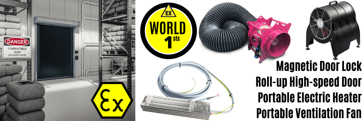
Thorne & Derrick have recently introduced a series of ‘World First’ ATEX innovations to the market; including the MFH Portable Hazardous Area Fan Heater.
View complete range of Electrical Heating Equipment & Products for hazardous areas and explosive atmospheres.
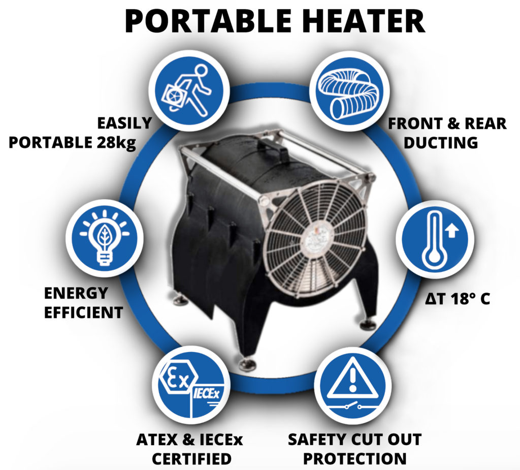
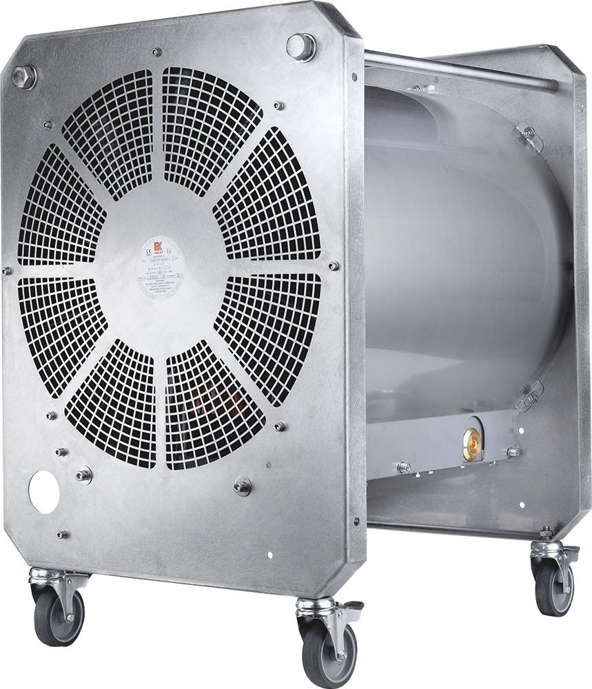
The MFH Portable Fan Heater manufactured by EXHEAT and Distributed Exclusively in the UK by Thorne & Derrick is the world’s first truly portable fan assisted heater with dual hazardous area ATEX & IECEX Certification. The portable heater has been extensively adopted by the process and hazardous area industries to safely provide temporary and portable air warming to workplaces in potentially explosive atmospheres.
See also, LFH Heater
EXPERTS IN EQUIPMENT FOR EXPLOSIVE ATMOSPHERES
LEADERS IN ATEX INNOVATION TO THE HAZARDOUS AREA INDUSTRIES
Thorne & Derrick are leaders in the development and distribution of Product Innovations that deliver significant improvements to clients plant, people and operational safety in the explosive atmosphere industries.
Your proactive problem solvers experienced in succession planning for the replacement of obsolete, non-conformant and legacy equipment in hazardous areas.
Your first-choice provider of innovative and competitive solutions to ensure ATEX & IECEx Compliance for Hazardous Area Electrical, H&V & Process Instrumentation Equipment to UK and international projects.
Control Panels | Plugs | Isolators | Enclosures & Junction Boxes | Lighting | Control Stations | Motor Starters | Heat Trace | Gas Detection | Flame Detection | Process Instrumentation | Process Heating | Ventilation Fans | Security Access Control
Competitive Prices | Extensive Stocks | Technical Support | Express Delivery

Hazcon Inc.
Explosion Protection
& Hazardous Area Equipment
Hazcon Inc. provides a full suite of consulting services for manufacturers of electrical equipment for hazardous locations and explosive atmospheres.
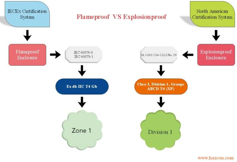
The protection technique that involves containing an explosion may be called “explosionproof” or “flameproof”. Although the international market for hazloc products is strong, based on a Zone system and supported by the Standard IEC 60079-1 for flameproof equipment, the North American market is also significant, supported by Standards in both Canada and the US for explosionproof devices.
In this Article, Hazcon address the differences between the requirements for explosion proof and flameproof enclosures and how to achieve “Ex db” and “Class I Division 1 (XP)” markings.
They also answer three important questions:
1) Can a product with “Zone 1, AEx db IIC T4 Gb” marking or “Ex db IIC T4 Gb” marking (Zone marking for North America) be installed in Class I, Division 1?
2) Can a product with “Class I, Division 1” marking be installed in Zone 1 hazardous areas in North America?
3) What is the best route for an IECEx approved product with a marking such as “Ex db IIC T4 Gb” to be approved for the North American market?
‘Explosionproof’ or ‘Flameproof’
Some electrical devices, even when operating under normal conditions, can produce arcing and/or sparking. If such a device is installed in a hazardous location (where there are or can be ignitable gases or vapours), an explosion can result.
One of the approaches used to protect electrical devices installed in such locations is based on the principle of containing an explosion, should one take place. There are two names given to this technique: “explosionproof” and “flameproof”.
This technique involves using an enclosure. Even if an explosion takes place within it, the enclosure prevents ignition and explosion from being transmitted to the area surrounding the enclosure – the area that contains flammable/ ignitable gases or vapours.
Although explosionproof and flameproof are similar, there are some differences. They are based on different certification systems (the first one being international and the other North American); they are therefore based on different Standards (IEC Standards vs. the North American Standards). They result in differences in the markings assigned to the product. Some of the compliance requirements are different.
It’s important to understand these differences if
- You want to achieve Zone classification system certification through the IECEx Scheme
- You want to achieve Class/division system certification through a North American certifying body so your product can be installed and used in in North America
- You want to achieve Zone system certification through a North American certifying body so your product can be installed and used in Canada OR the United States in Zone classified areas.
- You aren’t sure about the equivalency of Standards related to explosionproof or flameproof in Canada, the US, and internationally
- You want to certify your product to be installed and used anywhere in the world
- You need to know what additional requirements may apply if you want your existing certification recognized elsewhere in the world
Following is an explanation of the similarities and differences between explosionproof and flameproof. The differences may seem minor but are critical to manufacturers in the product design stage and when seeking certification.
Explosion proof
The term “explosionproof” applies to hazloc products approved by North American certification agencies using the Class/division system, for products to be used in North America.
Historically, the North American certification system is known for its use of a Class/Division classification system. Products to be installed in hazardous locations may be Class I, Division 1, for example. Hazloc products that are Class I Division 1 typically use the explosionproof protection technique. Products using the intrinsic safety or purging and pressurization Type X protection techniques can also get Class I, Division 1 certification.
Relevant Standards for Explosionproof
Requirements for the “explosionproof” protection technique are documented in North American Standards, namely those developed by the Canadian Standards Association (CSA), Underwriters Laboratories (UL), FM Approvals (FM) and the American National Standards Institute (ANSI).
A product wanting to get a Class I, Division 1 marking using the explosionproof protection technique must comply with Standard UL 1203 for the US and CSA C22.2 No. 30 for Canada. Keep in mind that all electrical products in North America must also first comply with what are called general safety (also known as ordinary location) Standards. This is the one of the major requirements for obtaining a hazardous location certification for North America.
These two Standards also address the designation of gases into groups. The gas groups for Class I Division 1 are A, B, C, and D. Gas groups indicate how easily ignited the gases within that group are. Gases in group A (Acetylene) are the most ignitable.
And the North American Standards noted also address the Temperature Class (T-class) of the device: T6 to T1 with some sub-groups for each.
Flameproof
The term “flameproof” applies to hazloc products certified as follows:
- By the International IEC Standards, based on the Zone system, for use internationally (but not in North America)
- By North American certification agencies, based on the Zone system, for products to be used in Canada or the US (the requirements differ)
Flameproof always applies to certifications using the Zone system.
There are additional Standards specifically for electrical devices using the flameproof protection technique. They are as follows:
- IEC 60079-1, which covers the technical requirements of products seeking Ex db marking using the flameproof technique for IEC certification for use internationally (but not in North America)
- UL 60079-1, which covers the technical requirements of products seeking Zone-based certification from North American certification agencies for use in the US
- CSA C22.2 No. 60079-1, which covers the certification requirements of products seeking Zone-based certification from North American certification agencies for use in Canada
Under the Zone classification system, there are three gas groups: IIC, IIB and IIA. Similar to the Class/division system, the word “Group” refers to degree of risk of an explosion. In the Zone classification system, however, gas Group IIC is the most ignitable gas.
Differences in the Markings of Explosionproof vs Flameproof
Products that have been certified are given markings that are used on product nameplates, in product literature, and in installation manuals. Because explosionproof and flameproof are based on differing classification systems and Standards, the markings are naturally different as well.
Explosionproof Markings
The Explosionproof markings for products that comply with North American Standards, based on the Class/division system, include their Class and Division. The marking indicates the ignitability of the gas (the Gas Group), as well as the T-class of the electrical device.
Following is an example of a Class/division marking of a product that has been certified by a North American certification agency for use in North America. The “XP” indicates that the protection method used is explosionproof:
Class I, Division 1, Groups A, B, C, D; T4 (XP)
Flameproof Markings
The flameproof markings for products that comply with Zone system certification requirements vary, depending on where the certification was achieved (through IEC or in North America).
Ex db IIC T4 Gb
The Ex stands for hazardous location. The “db” refers to flameproof. IIC refers to the gas group (this could be II A, B or C). The T4 refers to the temperature class (it could be T1, 2, 3, 4, 5, or 6) and the Gb refers to the Equipment Protection Label, Gb is for Zone 1, (Ga is for Zone 0 and Gc is for Zone 2).
Markings for products whose certification was achieved in the US for use in the US are shown in this example: Zone 1, AEx db IIC T4 Gb Or Class I, Zone 1, AEx db IIC T4 Gb
- Markings for products whose certification was achieved in Canada for use in Canada are shown in this example: Ex db IIC T4 Gb
Answers to Common Questions
1. Can a product with Zone 1, AEx db IIC T4 Gb marking or Ex db IIC T4 Gb marking (Zone marking for North America, as per CSA and UL Standards) be installed in Class I, Division 1?
No. In order to get a product installed in a Class I, Division 1 area, the product must comply with UL 1203 for installation in the US and CSA C22.2 No. 30 for installation in Canada. Given compliance with these standards, (also compliance with ordinary location standards,) then Class I, Division 1 marking can be obtained.
2. Can a product with Class I, Division 1 marking be installed in Zone 1 hazardous areas in North America?
Yes, it is allowed as long as the gas groups and temperature class are compatible. The marking will remain Zone 1, AEx db IIC T4 Gb, for example.
3. What is the best route for an IECEx approved product with a marking such as Ex db IIC T4 Gb (for example) to be approved for the North American market?
First, an IECEx certified product will need to comply with the general safety (also called ordinary location) Standards for North America. These Standards are for consideration of electrical shock and fire hazards.
Then, in order to get Zone marking for North America, the product must comply with North American national deviations as provided in UL 60079-1 and CSA 60079-1 Standards. The marking which results will be Zone marking for North America.
In order to get Class I, Division 1 marking for North America, the product must comply with UL 1203 and CSA C22.2 No. 30, Complying with IEC 60079-1 for flameproof enclosures does not guarantee that a product will meet the requirements of CSA C22.2 No. 30 and UL 1203 for Class I, Division 1.
Major Differences Among the Requirements Noted in the Standards
- It should be noted that Gas grouping is different for Class/Division in UL1203/ CSA C22.2 No. 30 Standards versus the IEC Standards: notably, Acetylene (North America Group A) and Hydrogen (North America Group B) are separated out in UL1203 and CSA C22.2 No. 30, whereas IEC 60079-1 groups them together as Group IIC.
- In the Class/Division classification system, Gas Group A is the most dangerous whereas in IEC 60079-1, Group IIC is the most dangerous.
- The IEC and UL/CSA Standards differ slightly in terms of the requirements related to some measurements (joint widths, gaps and holes interrupting flame paths to name several).
- North American Standards (UL1203 and CSA C22.2 No. 30) require a minimum wall thickness for the enclosure as set in the Standards but there is no such a requirement in IEC 60079-1.
- There are different requirements for any non-metallic materials that make up part of the enclosure on which the protection technique is based. In Standard UL 1203, for example, non-metallic enclosure requirements are more stringent.
- Differences exist concerning testing for purposes of certification. There is a slight difference in gas mixtures and number of explosions for the testing as per Standards UL 1203 and IEC 60079-1. Testing based on CSA C22.2 No. 30 seems to be similar to testing requirements set in IEC 60079-1. As per North American Standards, when lengths of conduits are required to be connected to the equipment for explosion tests, these lengths are to be evaluated as part of the test apparatus. This is not specifically required in IEC 60079-1.
Summary
The protection technique that involves containing an explosion may be called “explosionproof” or “flameproof”, depending on which classification system is involved.
Although the international market for hazloc products is strong, based on a Zone system and supported by the Standard IEC 60079-1 for flameproof equipment, the North American market is also significant, supported by Standards in both Canada and the US for explosionproof devices.
North America, which has traditionally used the Class/Division system of classification, has adopted new Standards based on the Zone system, which appear to mirror their international counterparts. Be aware, however, that there are additional requirements, known as national deviations, between Standards (CSA C22.2 No. 60079-1 versus IEC 60079-1, for example).
Opportunities abound to get new electrical products into the global marketplace. Be ready to comply with the requirements if you wish to achieve multiple certifications through differing classification systems.
The protection technique you use to contain any explosions may be called either “explosionproof” or “flameproof”, the Standards to which you must comply differ, and the markings on your product will illustrate which classification system you chose.
Pursue certifications (of new or existing products) with your eyes open: be sure to anticipate and comply with the certification requirements and know in advance how your market will perceive the markings your product will achieve, based on your choices.
Further Reading
Information Courtesy
Behzad Nejad, P. Eng. (Hazcon)
Director & Consulting Engineer at Hazcon Inc.; Hazardous Locations Consulting Services; IECEx, ATEX, CEC & NEC
Specializing in the design, safety and approval of electrical equipment for hazardous locations.
Mr. Nejad has over 15 years of experience as an Electrical Engineer and is a sought after professional in the hzardous area and explosion protection industry. He is fully-qualified at the advanced level of all hazardous locations protection techniques including Intrinsic Safety & Non-incendive, Explosion Proof & Flame proof, Increased Safety, Non-arcing, Purging and Pressurization, Encapsulation, Optical Radiation, and Dust-tight enclosures. Mr. Nejad’s tenure in the industry includes six years at the CSA certification agency, working closely with manufacturers (Emerson, GE, ABB, Siemens, Endress-Houser, VEGA etc.) as a technical and certification engineer for Hazardous locations equipment.
EXPERTS IN EQUIPMENT FOR EXPLOSIVE ATMOSPHERES
leaders in ATEX Innovation To The Hazardous Area Industries
Thorne & Derrick are leaders in the development and distribution of Product Innovations that deliver significant improvements to clients plant, people and operational safety in the explosive atmosphere industries.
Your proactive problem solvers experienced in succession planning for the replacement of obsolete, non-conformant and legacy equipment in hazardous areas.
Your first-choice provider of innovative and competitive solutions to ensure ATEX & IECEx Compliance for Hazardous Area Electrical, HVAC & Process Instrumentation Equipment to UK and international projects.
Control Panels | Plugs | Isolators | Enclosures & Junction Boxes | Lighting | Control Stations | Motor Starters | Heat Trace | Gas Detection | Flame Detection | Process Instrumentation | Process Heating | Ventilation Fans | Security Access Control
Competitive Prices | Extensive Stocks | Technical Support | Express Delivery
A Series of Articles to educate and inform those involved in the Hazardous Area & Explosive Atmosphere industries.
This Article is number 8 of 8 in the ATEX Safety & Explosive Atmospheres series.
Republished with the kind permission of Declan Barry, Managing Director of ATEX Explosion Hazards Ltd.
Also in association with INBUREX Consulting.
Declan Barry has an objective to make the industry safe by installing the appropriate explosion protection solutions to industry with full back up services. With 42 years of experience providing Explosion Hazard Services to the process industry, ATEX Explosion Hazards Ltd have a wide range of expertise within their group of companies.
This is the final article in a series of eight articles, which aim to help you establish a simple basis of safety in your plant and dispel some of the myths associated with process and safety risk assessments.
Management Procedures
Do we need to take precautions, as part of our managerial responsibilities and if so, why and to what extent? Well, there may be a risk of injury or fatality (to Plant Operators or members of the public), there are Statutory Requirements (Legal Obligations) which we must adhere to and there are consequences when things go wrong:
- Interruption to the business
- Fines for breach in legislation
- Loss of market share
- Loss of customer confidence
- Harm to corporate image
Risk Matrix
We need to ask ourselves, is the risk we have identified, high enough to justify the investment in order to reduce it to a tolerable level. To this end, a commonly used Risk Matrix is shown below.
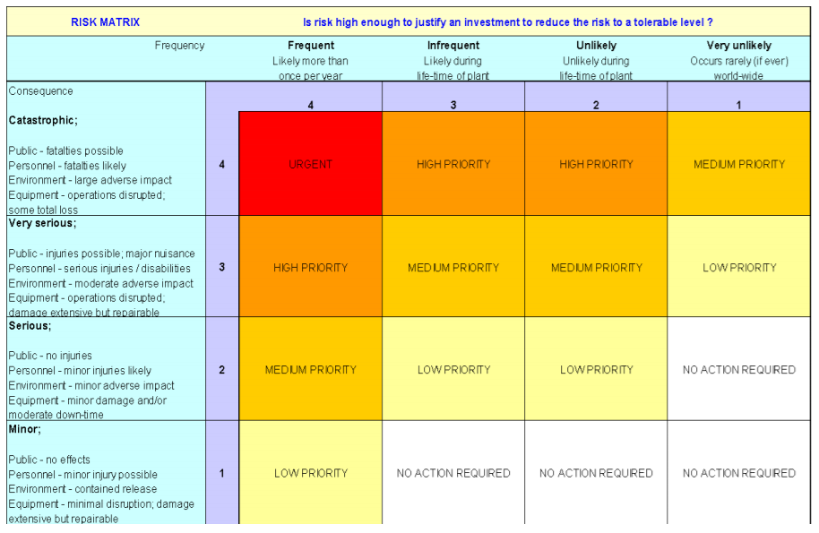
More detailed forms of the matrix with costs, event frequencies, etc. are available but this shows the general idea.
Today, risk assessments are common place and used in all walks of life, often without a proper understanding of the true meaning i.e. risk is the product of probability (of the undesired event) and consequence. The categorization of a risk as insignificant does not necessarily mean that it will be perceived as such by those affected; it relates rather to the action required by the decision maker.
Neither does tolerable mean acceptable – it refers to the willingness to live with a risk to secure certain benefits and in the confidence that it is being properly controlled. To tolerate a risk means that we do not regard it as negligible or something we might ignore, but rather as something we need to keep under review, and reduce still further if, and as, we can (Hazard Identification and Risk Assessment – Geo Wells, IChemE 1996).
Management Obligations
Management obligations are wide ranging and for that reason, they can be quite daunting. However, some simple measures can be put in to place which not only help massively reduce risk but also do it both effectively and economically.
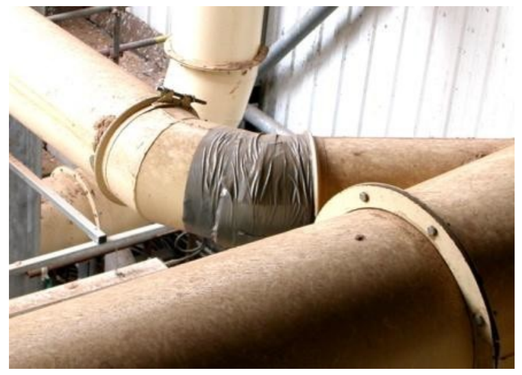
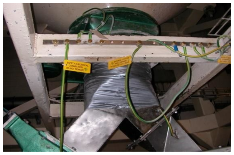
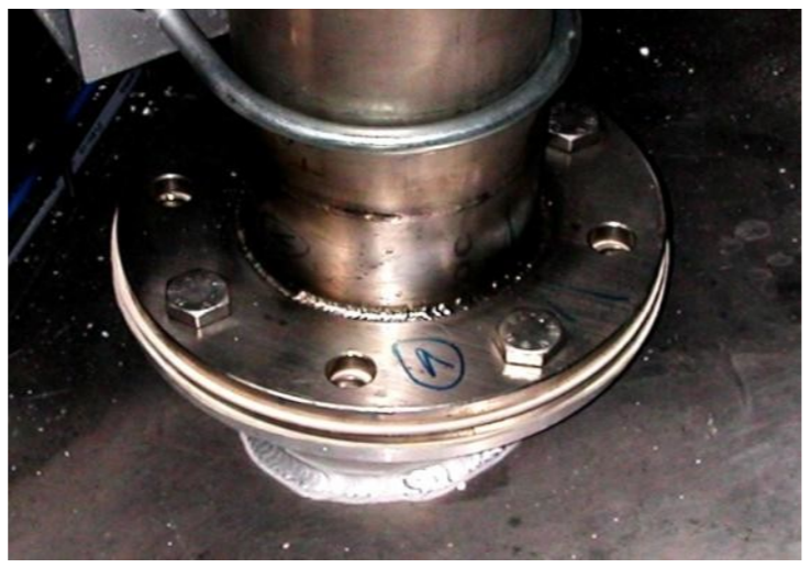
For example, bearing in mind the need to control releases of the ‘hazardous material’, all equipment must be well maintained and subject to regular inspections, in line with good engineering practice. The use of improper seals/joints IS NOT acceptable. For example, ‘gaffa tape’ should never be used on leaking joints. Moreover, there is a tendency for this type of temporary fix to become permanent. Likewise, seals (and replacement thereof) need to be robust to reduce the extent of dust egress.
Items of plant and equipment must be sealed effectively i.e. not simply relying on gravity to hold a door or panel shut. For example, often inspection hatches are not bolted down – although this might be considered unnecessary for (say) granular materials, it sends the wrong message to operators and maintenance staff (e.g. there should be a
consistent approach).
Such items should be bolted shut and form an effective seal; although this may not lead to the formation of a hazardous area per se, fugitive emissions from poorly sealed plant will give rise to housekeeping issues.
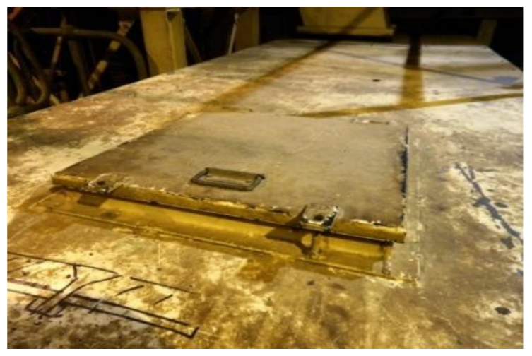
Some inspection hatches, which by their nature are opened routinely, should be sealed and afforded a ‘quick-release’ opening mechanism e.g. sprung-loaded, whilst other ‘access’ panels should be sealed and bolted shut.
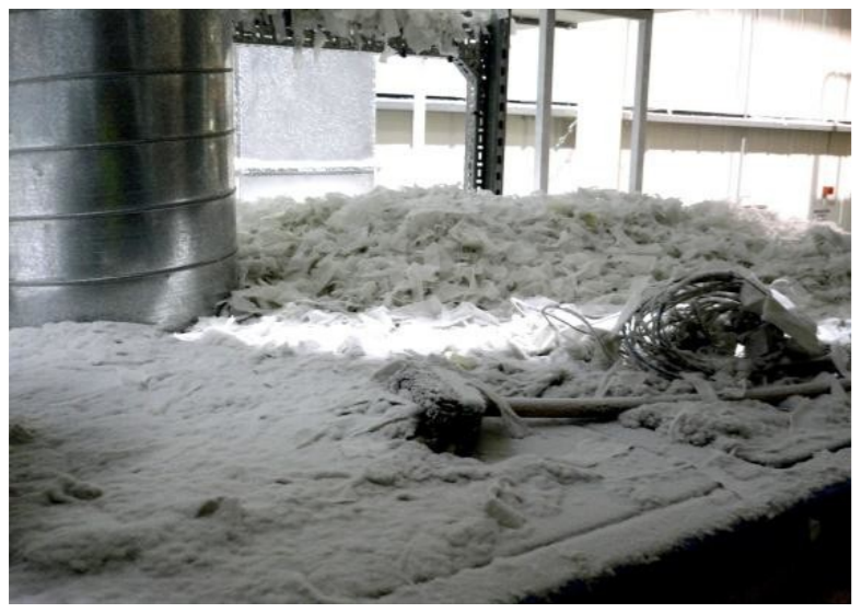
Air-jetting (on dust deposits) must not be used – this simply moves dust around in to spaces which are even more inaccessible and it aggravates the problem. Use of dust extraction points (where provided) or vacuuming when opening up equipment should be encouraged – this will help reduce the cleaning frequency.
If extraction is provided for dust control, make sure the ‘capture’ velocities are correct for the materials in use. Also, all too often there is no indication of poor performance i.e. low flow, so fit a low-flow (LF) alarm with low-low-flow (LLF) trip.
If the extraction fails, you’ll know about it rather than throwing manpower at what appears to be more and more dust deposits!
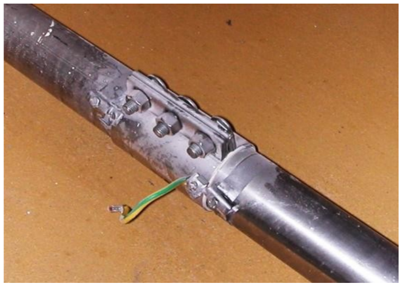
From an operational (and safety) viewpoint, Conveyors should comprise one or a combination of the following – blockage detection, tracking sensors, motor overload protection, rotation sensors, etc. and ALL metal items should be bonded to earth.
Procedures must be in place which ensure that Hot Work is controlled. Indeed, ALL plant personnel must be made aware of both the potential ignition/explosion hazards associated with their plant and the means of control. To this end, formal DSEAR / ATEX Training Sessions should be conducted on a regular basis and Attendance Certificates issued.
HAZOP studies should be considered. This is a form of design review – the key features being it is a team study, it concentrates on how well the design will cope with abnormal conditions (rather than how well it will perform in normal operation) and it is systematic and detailed. A study considers each process stream or pipeline and vessel examining for each possible cause and consequence of a wide range of process upsets or abnormalities. It is a very thorough but mainly qualitative approach to ‘Failure Mode and Effect Analysis’. When done correctly, the technique is extremely powerful, often highlighting many ‘operability’ issues not just ignition hazards.
Management of Change Procedures
Portable equipment is often brought in to work areas for a specific reason and with good intentions e.g. more heat, more light, etc. However, it is essential that you assess this ‘change’ i.e. follow your Management of Change Procedures – assuming you have some of course!
IF NOT, WHY NOT? The heat lamp may have zero consequences, but there again, it might have been brought in to increase the evaporation rate of solvent wet material – Yes, it happens!
As we’ve said, electrical and mechanical equipment must be certified for the specific hazardous area AND ‘process specific’ sources such electrostatic ignition e.g. from solvent or powder transfers, etc.
Predictive Maintenance
Good engineering practices and strict maintenance regimes are vital also. Hopefully, the days of ‘if it ain’t broke don’t fix it’ are long gone; and now there is a ‘new kid’ on the block – Predictive Maintenance
The potential failure of ‘process critical’ or ‘safety critical’ items should be monitored since this will help identify problems BEFORE they arise – the key benefit being that YOU shut down the plant when it’s convenient to you rather than having an unscheduled breakdown (which is never convenient). In the example shown below, Roller Bearing defects were identified early, by vibration monitoring.
ATEX Establishing a Basis for Safety
This is the eighth and final article in our series which aims to help you establish a simple basis of safety in your plant and dispel some of the myths associated with process and safety risk assessments. We hope you have found this series of articles both informative and helpful Stay safe.
More Explosion Hazards Articles
EXPERTS IN EQUIPMENT FOR EXPLOSIVE ATMOSPHERES
LEADERS IN ATEX INNOVATION TO THE HAZARDOUS AREA INDUSTRIES
Thorne & Derrick are leaders in the development and distribution of Product Innovations that deliver significant improvements to clients plant, people and operational safety in the explosive atmosphere industries.
Your proactive problem solvers experienced in succession planning for the replacement of obsolete, non-conformant and legacy equipment in hazardous areas.
Your first-choice provider of innovative and competitive solutions to ensure ATEX & IECEx Compliance for Hazardous Area Electrical, HVAC & Process Instrumentation Equipment to UK and international projects.
Control Panels | Plugs | Isolators | Enclosures & Junction Boxes | Lighting | Control Stations | Motor Starters | Heat Trace | Gas Detection | Flame Detection | Process Instrumentation | Process Heating | Ventilation Fans | Security Access Control
Competitive Prices | Extensive Stocks | Technical Support | Express Delivery