T&D are a world-class business committed to ensuring the correct installation and application of all explosion-proof products we distribute.
Where applicable installer training and support services including site surveys can be made available – although we are not a direct provider of training services we understand that danger cannot be understated in the hazardous area industries.
To maintain our hazardous area technical knowledge, skills and expertise we depend upon Roxby Training Solutions and in this post we outline their range of Hazardous Area Training Courses – whether you require ATEX Flow Meters, Zone 2 Air Heaters or Hazardous Area Solenoid Valves, T&D can be trusted to supply the correct products for potentially explosive atmosphere applications without any hidden dangers.
HAZARDOUS AREA KNOWLEDGE & EXPERIENCE
Roxby Training Solutions are a specialist training provider with more than 40 years of experience with instrumentation, measurement and control providing engineering training in both UK and international markets.
Roxby have a specialist focus on CompEx and Instrumentation but also offer mechanical, electrical and health & safety training courses across their portfolio.
Instructional staff have over 140 years industrial experience between them and offer a balance of 50% theory and 50% practical with assessments across their courses to successfully achieve set outcomes and prove competence.
Roxby Training Solutions also put together bespoke, UK based, hazardous area industry training programs for overseas clients using a series of sub-contract training providers extending this to overseas delivery where opportunities present themselves.
All courses are taught in English however other languages are available where required. Roxby Training Solutions hold the following accreditation’s:
Roxby Training Solutions aims are:
To be an outstanding training provider for learners
To offer accredited hazardous area training solutions where possible
To offer training that is effective in securing employment opportunities
To offer training that is effective for those wishing to pursue continued professional development
To offer practical hands on training where possible
To offer inspirational and enjoyable training
To work and achieve together
Provide effective opportunities for training on customer premises and locations outside of our Stockton and Stallingborough (North East Lincolnshire) facilities
Roxby’s Training Solutions Limited – CompEx Hazardous Area Training Provider
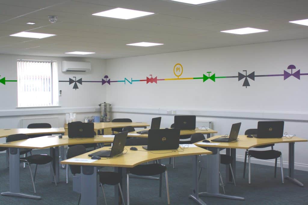
Roxby Training Solutions has first class facilities located in Stockton and Stallingborough which house an extensive range of Electrical and Instrumentation equipment, chosen to provide a realistic reflection of the type of equipment likely to be found in the typical workplace.
Courses can be carried out at customers’ premises if preferred, provided that facilities are suitable.
Roxby Training Solutions Classroom
As part of the business, Roxby also specialise in a full range of outsourced services with the skills and experience to act as your in-house training/recruitment manager:
Undertaking a skills needs analysis of your workforce
Reviewing performance appraisals for hazardous area training needs
Sourcing appropriate training
Ensuring you receive the optimum return on your training investment
Managing your training budget
Providing a single monthly invoice, broken down as applicable
Sourcing and developing new and tailor-made solutions
Providing information and assistance with legislation changes affecting training needs for your business/industry
Providing suitably qualified, competent candidates to enhance your workforc
Roxby Training Solutions
Hazardous Area Courses
CompEx is the globally recognised training and assessment scheme for electrotechnical crafts personnel who work in potentially explosive atmospheres and hazardous area location industries, such as on-and-off-shore oil and gas, pharmaceuticals, energy, chemical industries, etc.
JTL who is the National training agent for the Electrical contracting industry has been appointed to develop, operate and manage the training provision globally and has licensed and accredited a number of centres to deliver the training and assessment.
As an approved JTL CompEx Assessment Provider, Roxby offer CompEx ‘F’ Foundation Ex01, Ex02, Ex03 and Ex04 Assessments for full CompEx and CompEx Refresher, Ex05 & Ex06 Dust Modules, Ex11 Mechanical, Ex12 Design Engineers and Ex14 Responsible Person, delivered in their training centres or at customer’s premises where suitable.
All T&D Sales Engineers hold CompEx Certificates (Hazardous Awareness Course EX F) and undertake advanced and ongoing Explosion Protection training with suppliers – we can be safely trusted to specify and supply Electrical, Mechanical, Process & Instrumentation Equipment for use in hazardous areas and explosive atmospheres.
Electrical Equipment in Hazardous Areas and Explosive Atmospheres
Details of forthcoming Hazardous Area Training courses are available here, Book A Course.
See how we service and support our key markets and hazardous area industries in the following SlideShelf of industry infographics.
Invitation – network, engage, promote
Thorne & Derrick are inviting you to join LinkedIn’s fastest growing Discussion Group – Process & Hazardous Area Industries : Heat Tracing, Gas Detection, Fluid Control & Flow Measurement. News, projects, videos, promotions, whitepapers, jobs, webinars, press plus much more.
ABOUT US
Thorne & Derrick International are your single-source supplier of Electrical, Mechanical, Process & Instrumentation Equipment. T&D provide an outstanding service to UK and international customers – we are highly customer responsive and absolutely committed to providing a world-class service.
T&D supply utilities, power, renewable energy, construction, rail, manufacturing, food/beverage, mining, oil, gas and petrochemical industries – distributing 100,000+ products from 100+ manufacturers from multi-million pound stocks. Since 1985 we have established a solid reputation based on service, integrity and trust.
By Chris Dodds : estimated reading time 4 minutes
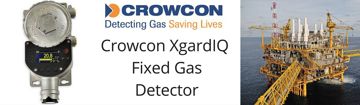
Crowcon XgardIQ Smart Fixed Point Gas Detector
The Crowcon XgardIQ is the next generation of fixed gas detectors from Crowcon and has been manufactured to enhance site safety and minimise the time workers must spend in hazardous areas exposed to harmful gas.
The fixed gas detector is versatile, compatible with Crowcon’s full range of sensor technologies and is available fitted with a variety of flammable, toxic or oxygen gas sensors.
Andy Avenell, senior business development manager at Crowcon, said while explaining the product development;
“We spend a significant amount of time talking to engineers and operators in oil and gas facilities, petrochemical and chemical plants and other high risk areas. The experiences and insight gained from such sites has been instrumental in the specification development of XgardIQ.”
When lives and real estate are at stake, the Crowcon XgardIQ provides reliable notification system of the presence of harmful, explosive and flammable gases. This minimises the amount of time that a worker must spend in a hazardous area.
Hot Swappable Sensors
The XgardIQ minimises the amount of time spent between swapping sensors and performing routine maintenance. The sensors can be ‘hot-swapped’ without the need for a hot work permit. The old module can be replaced with a new pre-calibrated one or removed for testing and calibration in a safe area.
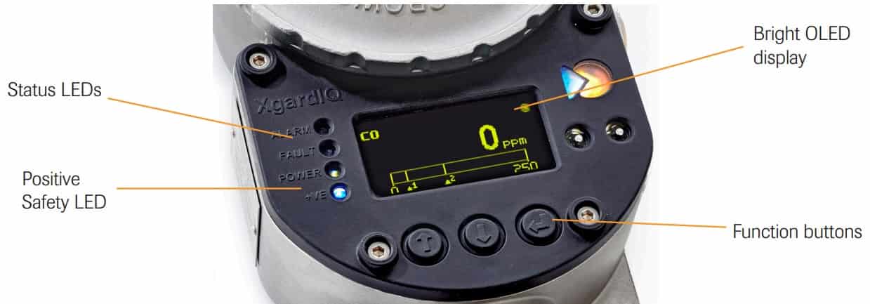
Crowcon XgardIQ Fixed Gas Detector Product Interface Features
Versatile sensor options
The modern plant environments often require a varying degree of gas detection diversification. The Crowcon XgardIQ can offer this versatility and wide application of gas detection with a single product.
Positive safety
Crowcon’s unique positive safety feature reassures operators that the XgardIQ is functioning properly by alerting when there is any irregular events that may effect the sensors performance. This puts the XgardIQ ahead of other sensors that may otherwise cease to function when exposed to extreme environmental conditions.
When the detector is working safely, the bright blue +ve safety LED remains constantly turned on. If there are any abnormal operating conditions that are detected, the +ve LED warning light will flash and a warning light message displayed.
Improved safety and flexible signal outputs
Crowcon XgardIQ Gas Detector Display And Input
The Crowcon XgardIQ is an intelligent and versatile fixed point gas detector providing comprehensive and powerful output signal options. These include an analogue 4-20mA signal with auto sink/source detection feature and RS-485 Modbus communications provided as standard.
The XgardIQ minimises the time that personnel have to spend in potentially hazardous areas by using simple, hot-swappable sensor modules. Sensors can be both bump tested or calibrated in-situ or alternatively can be removed in seconds using one hand. They can then be replaced with pre-calibrated sensors or re-calibrated in a safe area.
All functions of the Crowcon XgardIQ and any adjustments can be made via the integral keypad without the need to purchase and special tools or equipment.
Compatability
The XgardIQ is compatible with virtually any control system including gas detection panels, PLC’s, DCS’s and SCADA systems. This makes the detector easier to install and reduces costs associated with installation.
When calibrating the XgardIQ sensor, calibration gas must be applied used the calibration cap also available from Crowcon. Typically, a flow rate of 0.5 litres per minuter is appropriate however this may vary for different sensor types.
Calibration can be performed with a suitable gas concentration from 10% of the scaled sensor range to 100% of the maximum sensor range. The minimum calibration gas concentration that can be used is 10% of the scaled range. ♦ LV Power Products | Junction Boxes & Enclosures ATEX | Plugs ATEX | Control Stations ATEX | Isolators ATEX
Follow our Showcase Page on LinkedIn to receive hazardous area product innovations, industry news, whitepapers, videos, technical tips and training webinars for professionals involved in the explosive atmosphere industries.
T&D are the UK’s largest stockist of Drum, IBC & Tank Heaters & Jackets. Delivering UK & Worldwide.
T&D’s online library of Drum, IBC & Tank Heating applications is now updated to include the following : fermenting cider within IBC’s for the food and beverage industry.
Visit Silicone Heaters for details of electric surface heating solutions – flexible silicone heaters can be applied to heat the most complex shapes, geometries, curves and pipes.
Cider fermentation is carried out at a temperature of 4–16 °C (40–60 °F). This is low for most kinds of fermentation, but is beneficial for cider as it leads to slower fermentation with less loss of delicate aromas.
HEATING APPLICATION
T&D, The Hazardous Area Heating Specialists
Frost Protection
Reduce Viscosity
Temperature Maintenance
Low Temperature Heating (0-20 degrees Celsius)
Medium Temperature Heating (21-50 degrees Celsius)
High Temperature Heating (50 degrees Celsius+)
Other ✓ Fermenting Cider
IBC Heating Jackets – T&D supply heating and insulating jackets for plastic or steel metal cage IBC’s for bulk liquid storage.
HEATING JACKET VOLTAGE
110 Volt
230 Volt ✓
Low Voltage
HEATING APPLICATION : DRUM, IBC, TANK OR VESSEL
25 Litres
50 Litres
105 Litres
205 Litres
1000 Litres ✓
Other
VESSEL MATERIAL
Steel
Stainless Steel
Plastic
Cardboard
Other ✓ – N/A
HEAT UP TEMPERATURE
0-5 degrees Celsius
5-20 degrees Celsius
20-50 degrees Celsius ✓
50-70 degrees Celsius
70+ degrees Celsius
N/A (Frost Protection)
HEAT UP TIME REQUIREMENT
0-4 Hours
4-12 Hours
12-24 Hours
24-48 Hours
N/A ✓ (Maintain)
Contact T&D for specification, support and sales of Electrical Heating Equipment for safe, industrial and hazardous area plant and equipment – we provide process temperature heating and frost protection (Winterisation) products for pipework, valves, IBC’s, drums and tanks.
T&D – Largest UK Stockist of Heat Tracing Cables. UK & International Delivery tel 00 44 191 4901547.
The Gas and Oil industries are obvious examples of where potentially explosive environments exist, but other industries have their own set of hazardous conditions that need to be monitored and controlled.
Fine particulates from sugar beet processing, wood dust, pharmaceutical powders and vapours from paint spraying processes are also examples of where equipment, including products designed and manufactured for “own” use, are not excluded from the requirements of the ATEX Directive.
In the Dangerous Substances and Explosive Atmospheres Regulations 2002 (DSEAR) an explosive atmosphere is defined as a mixture of dangerous substances with air, under atmospheric conditions, in the form of gases, vapours, mist or dust in which, after ignition has occurred, combustion spreads to the entire unburned mixture.
Atmospheric conditions are commonly referred to as ambient temperatures and pressures. That is to say temperatures of –20°C to 40°C and pressures of 0.8 to 1.1 bar.
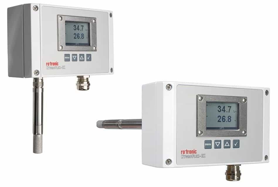
The Swiss based company, Rotronic Instruments, have been manufacturing and supplying ATEX transmitters for 20 years. The accuracy, durability and the reluctance of their probes to drift are seen as key attributes for companies who work in challenging conditions.
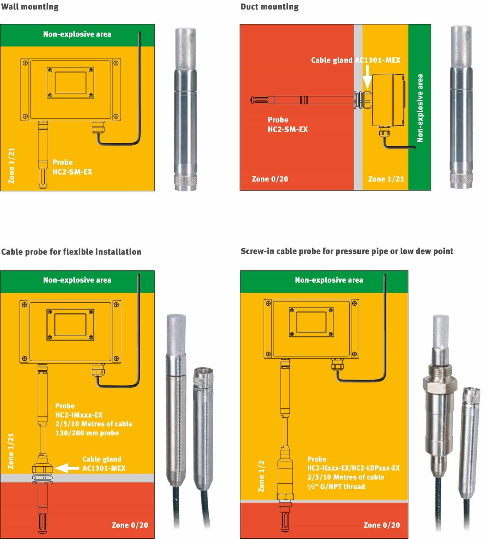
Rotronic’s Hygroflex5-EX range of Wall and Duct mount transmitters comply with all the current ATEX regulations. They have greatly simplified the installation and maintenance of ATEX equipment with galvanic separation and no need for an intrinsically safe power supply.
Their “Hot Swap” probes also significantly reduce line downtime when probes require calibration, enabling the user to attach a replacement sensor in seconds without having to unwire / rewire the transmitter.
All Rotronic probes have a working range of -40°C…+85°C / 0…100 %rh.
The aluminium housing of the transmitter (with display) -10°C…+60°C.
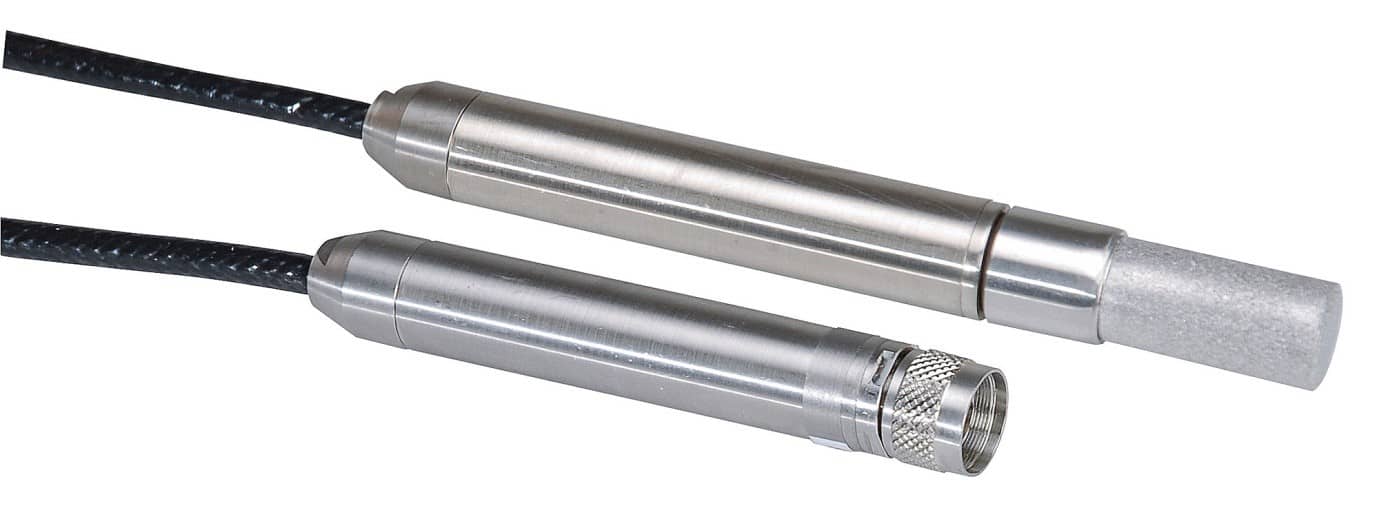
Rotronic Humidity & Temperature Probes
There are a range of probes available for the Hygroflex5-EX series to meet specific applications. Apart from the standard probe pictured above there are also cable probes with 2/5/10 metre cable lengths
Rotronic HC2-IM-EX humidity and temperature probe
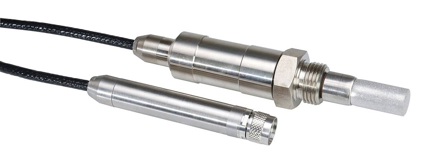
For processes that require humidity and temperature measurements under pressure the HC2-IE-EX probe may be employed. Available with either ½”G or ½” NPT thread and with cable lengths of 2/5/10m the probe is pressure resistant to 100 bar / 1450 PSI.
Rotronic HC2-IE-EX humidity and temperature probe
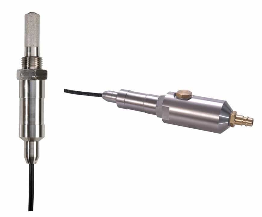
Low Dew Point Measurement
For those wishing to measure trace moisture in bodies such as gas pipes or compressed air systems the HC2-LDP-EX low dew point probe provides highly accurate dew point and temperature measurement up to 100 bar.
Rotronic HC2-LDP-EX dew point and temperature probe
Diagramatic layout for various Zone applications
Islands of Self-Sufficiency
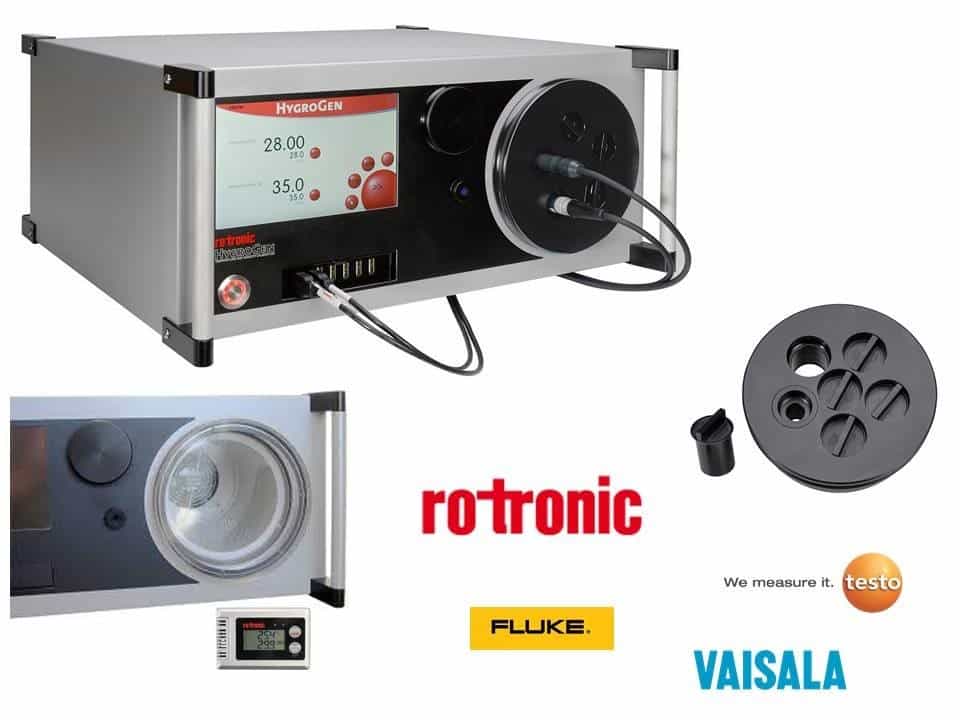
Layered on top of the DSEAR are a company’s individual practices and processes which determine how often instrumentation needs to be calibrated. In order to be self-sufficient, whether from a geographical or process driven perspective, many companies have also taken on board the Rotronic HygroGen2 humidity and temperature generator. The HygroGen2 sets a new standard in terms of portable calibration.
The generator is not exclusively for use with Rotronic probes. Many different manufacturers’ instruments can be calibrated by use of interchangeable diameter port sleeves, clear acrylic and even custom made doors. The user simply enters the required temperature and humidity set points to build a calibration profile.
The range of the Hygrogen2 is:
0….60°C (-5….60°C with optional range extension)
5….95 %rh (2….99 %rh with optional range extension)
Temperature control stability at equilibrium is better than ± 0.02 °C whilst humidity control stability is better than 0.1 %RH.
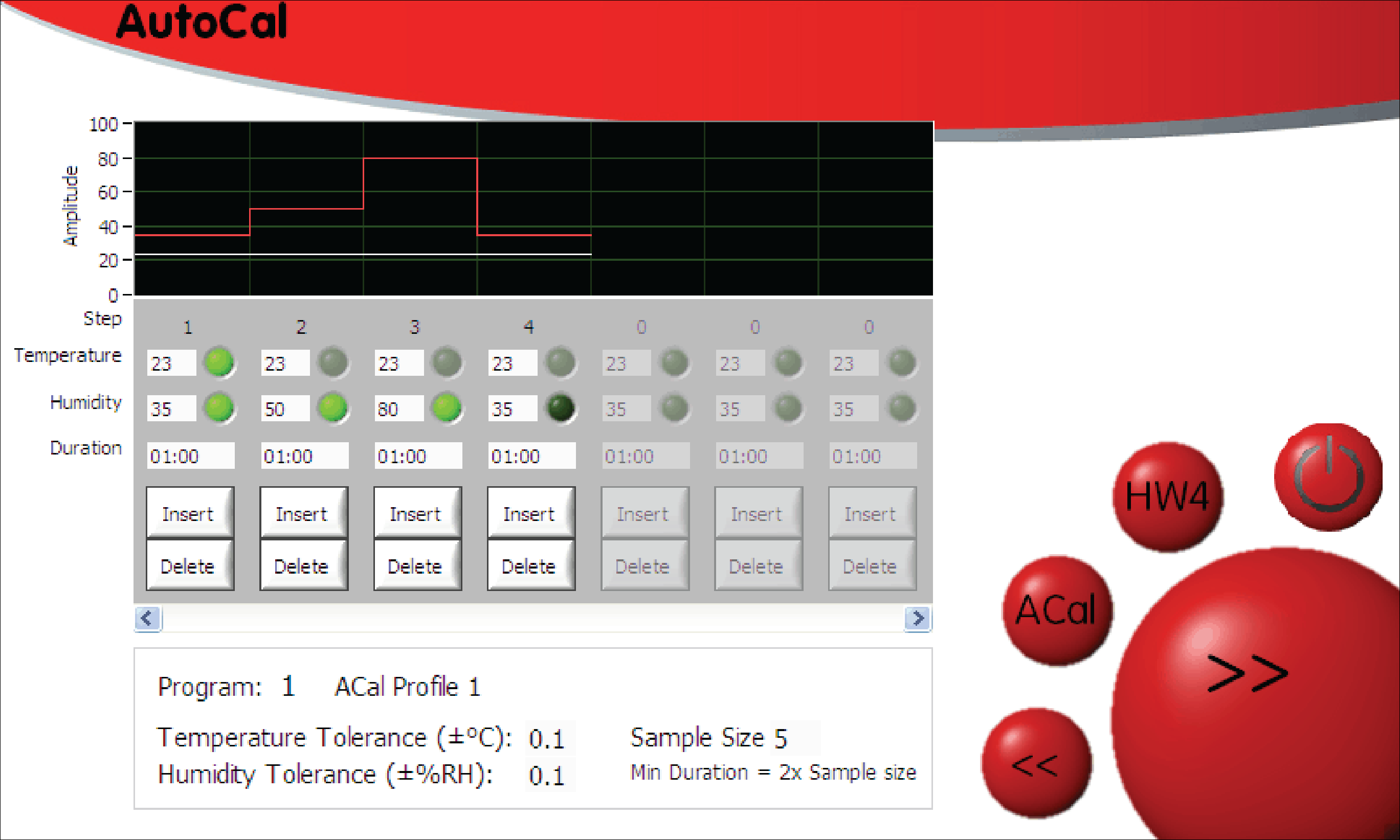
AutoCalibration
One of the main benefits of the HygroGen2, when used in conjunction with Rotronic’s HC2 series probes, is the ability to automatically calibrate the probes (and adjust if required). The AutoCal feature also creates a PDF calibration certificate for each probe under test.
20 storable programmes each with 200 set points provide the flexibility to quickly recall standard profiles for efficient use. Humidity equilibrium between set points is typically achieved in around 5 minutes – a considerable time saving when compared to using calibration salts!
“The installation of the Rotronic ATEX transmitters on a blending suite was simple and the hot swap probes will virtually eliminate line downtime.
The calibration of the probes is now so quick that we even adjusted them out, and back in, just to see how it would work and found the adjustments very logical and easy to complete.
For us, these new probes along with the HydroGen2 chamber represent a huge step forward in the calibration of temperature and humidity instrumentation” – Dave Gregson, GlaxoSmithKline
Reducing uncertainty in uncertain environments
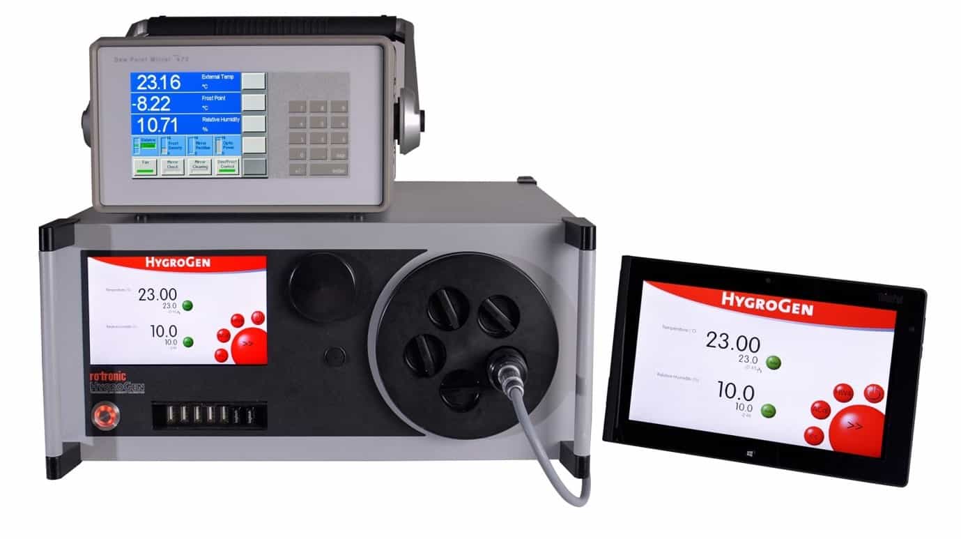
At the very highest level of measurement such as National Standards Laboratories, MBW chilled mirror hygrometers are considered to be the most accurate, reliable and consistent humidity measurement technology available. They are a primary reference standard against which other sensors are calibrated.
As well as calibration laboratories, MBW chilled mirrors are used in Oil and Gas applications, chemistry laboratories and throughout meteorological, processing, manufacturing, engineering and storage industries across a dew/frost point range of -95°Cfp to +95°Cdp and pressures up to 200 bar.
Rotronic has worked closely with MBW, to integrate their products into the HygroGen2 portable temperature and humidity calibration system. Particularly well suited is the MBW 473 Dew Point Mirror, whose RP2 measuring head is designed to be directly inserted into the working volume of the HygroGen2 chamber and work across its full range. Temperature and humidity probes from all manufacturers can be calibrated with typical expanded measurement uncertainty at ambient conditions of less than 0.7 %rh
Thorne & Derrick are Specialist Distributors of Hazardous Area & Explosion Proof Equipment with IECEx & ATEX Certifications to the onshore and offshore oil, gas, petrochemicals and process industries.
By Chris Dodds : estimated reading time 12 minutes
Liquid Level Sensors – Introduction
Over the years many techniques have been developed to provide information about the level of liquids or granular solids.
Many processes involving the storage, movement or processing of liquids require careful control of liquid level to ensure correct operation of the plant or equipment involved.
This application note reviews some of the more popular techniques used for liquid level sensing and describes the application challenges that need to be considered for satisfactory long term operation.
Basic Techniques
Direct Level Measurement
Most measurement methods can be categorised into one of two groups – direct and indirect (or inferred) methods.
As the term implies direct methods involve measuring the variable of interest (in this case the height of the surface level of a liquid) directly.
Common examples of direct measurement techniques that most people will have encountered are a dipstick to indicate the level of oil in an internal combustion engine sump.
Other examples are a ruler on the bank of a river to show the depth of water or a sight glass on a fuel tank to show the level of fuel within the tank.
These methods are simple and inexpensive but prone to errors and can only be used where an operator has access to the indicator or a CCTV system can be justified.
Where an indication of level is required remotely and greater precision or reliability are necessary then electronic / electro-magnetic / electro-mechanical direct measurement systems are often employed.
Indirect Level Measurement
In some circumstances an indirect method of measuring the level of a liquid may be preferable if not the only, viable, method.
For example, the liquid may be highly viscous (hot toffee) not allowing the free movement of a conventional float. In these circumstances other variables can be measured that correlate to liquid level.
For a liquid of constant density and temperature its mass is related to liquid level in a container of constant cross section.
So the weight of the contents is an indirect measurement of the height of the surface level.
Firing a beam of energy (ultrasonic, microwave or light) and measuring the time of flight for the reflected beam to be received also is indirectly related to the level liquid.
Indirect methods tend to be more costly and often are subject to more errors than direct methods.
Electrical Output
In terms of the electrical output(s) provided by liquid level sensors these can be grouped as binary on/off or semi-continuous and continuous analogue output.
Binary on/off sensors provide a switch contact change at each level of interest, usually 4 levels are of interest – AlarmHi, Hi, Lo and AlarmLo., but other configurations are possible. Semi-continuous sensors offer multiple values of analogue voltage, current or resistance to represent multiple liquid levels.
Depending on the physical size of the components used it is possible to resolve differences in liquid level as small as 1-2mm.
True continuous level indicators provide 0 to 10v or 4 to 20mA outputs representing every possible liquid level from zero to full scale.
These sensors measure the conductivity of the rising or falling liquid; this indicates a changing resistance related to liquid level.
Recent developments in this field include a resistive tape that is attached to the side of the liquid container.
Hydrostatic pressure causes the tape to change resistance this change can then be processed to provide a continuously varying current or voltage as an analogue of the liquid level.
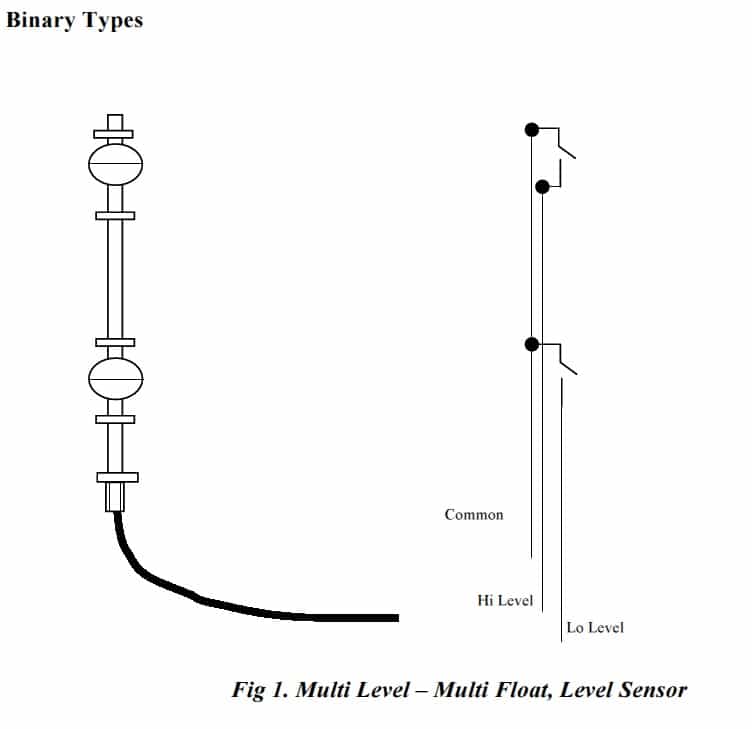
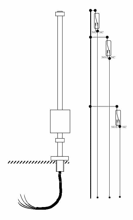
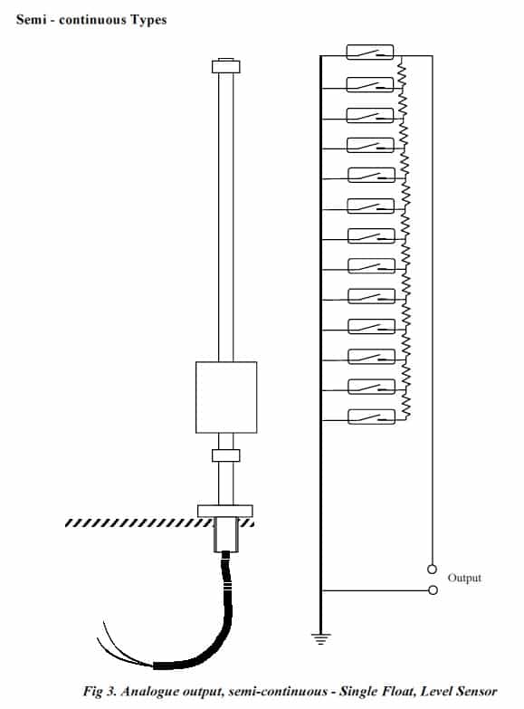
Deeter Electronics specialises in direct methods of sensing liquid level using magnetic float chambers and reed switches to indicate liquid level in a discrete level binary (on/off) or semi continuous (stepped analogue output) arrangement as shown in figures 1. to 3. below.
This technology is scaleable, affordable, relatively simple and highly reliable. By careful selection of the wetted materials, number and type of reed switch and magnetic floats, a broad range of applications can be addressed.
Fig 2. Multi Level – Single Float, Level Sensor
Reed Switches and Load Switching
As mentioned before Deeter Electronics specialises in liquid level sensors employing electromagnetic technologies.
This technique uses a buoyant chamber (float) with an annular magnet (doughnut shaped) sealed inside.
The magnetic field is concentrated in the hole in annulus. The float passes up and down a stainless steel or plastic float stem within which is contained a number of reed switches mounted at carefully chosen positions along the length of the stem.
As the float passes by each reed switch it operates indicating the presence of the float and thus surface level of the liquid.
There is a small difference between the surface level of the liquid and the actual position of the reed switch caused by the buoyancy of the float, the specific gravity of the liquid being measured the strength of the magnetic field and the sensitivity of the reed switch.
All of these factors are taken into account when the float is designed. Typically the stem of the float has an outside diameter less than 10mm.
Allowing for the wall thickness of the stem leaves less than 8mm depending on stem stiffness in which to mount the reed switches and electrical wiring or printed circuit board. Clearly the reed switches are quite small.
This small size limits the electrical switching capabilities of the reed switch contacts. Despite this limitation currents in the ampere range and voltages up to 500v can be safely and reliably switched.
However, once subjected to an overload, reed switches become erratic and unreliable in their operation; sometimes refusing to open circuit or make a good low resistance connection.
The electrical ratings for reed switches are always stated for purely resistive loads.
Rarely are loads purely resistive, this can lead the unwary user into difficulties. Even in low voltage systems high transient voltages and currents can occur which if switched by the reed switch, without adequate protection circuitry, will damage the contacts and cause unreliable operation thereafter.
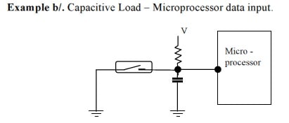
Capacitive Loads
Capacitive loads are characterised by high initial charging currents and if the load is then shorted, a high discharge current.
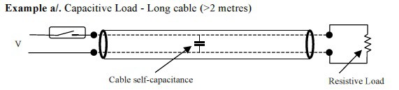
Unless protection circuitry is applied the switch will be damaged by these currents and become unreliable. Examples of capacitive loads are shown in the diagrams below.
When the reed switch contacts close the self-capacitance of the cable is charged to voltage V. Because there is very little resistance in the charging circuit the instantaneous current that flows can be very large.
When the reed switch closes the capacitor is discharged. Because the resistance in the circuit is very low the instantaneous discharge current is very high and damage is caused to the reed switch contacts.
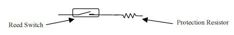
Protection Circuitry for Capacitive Loads
Limiting the large current in the charging and/or discharging mode provides protection. Typically inserting a 27-ohm resistor in series with the reed switch contacts is sufficient to limit the charging/discharging current to safe levels.
To calculate the resistor value for your specific application divide the charging voltage in volts by the safe maximum reed switch switching current in amps.
This gives the reed switch series protection resistance value in ohms. Choose the nearest higher standard value resistor.
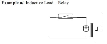
Inductive Loads
Inductive loads are characterised by current flow lagging the applied voltage and large reverse emf’s being generated when the load is de-energised.
Unless protection circuitry is applied the reed switch contacts will be damaged by the reverse emf’s generated when the load is de-energised. Examples of inductive loads are shown in the diagrams below.
Because relays typically have higher current and voltage switching capabilities they are often used to buffer the reed switch from switching the load directly.
However, relays are inductive and this can cause damage to the reed switch contacts.
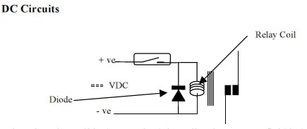
Relay coils can have sufficiently high inductance that switching the coil current with a reed switch causes damage to the reed switch contacts caused by arcing due to the high reverse emf that is induced in the coil as it is de-energised.
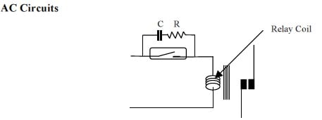
Depending on whether the coil is AC or DC energised the protection circuitry varies as shown below.
Protection Circuitry for Inductive Loads AC Circuits
The capacitor and resistor in parallel with the reed switch absorb the energy stored in the relay coil magnetic field when it is de-energised.
This protects the reed switch contacts from damage due to electrical arcing.
When the relay coil is de-energised the collapsing magnet field induces a voltage in the coil which is in reverse polarity to the supply voltage.
The diode forms a short circuit across the relay coil and safely absorbs the stored energy.
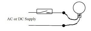
Incandescent Lamp Loads
Incandescent lamps, also called filament lamps, are sometimes used in liquid level measurement systems to provide an easily visible indication of the current liquid level. They are inexpensive and if used properly have a long and reliable life.
Whilst, as an electrical load, they are mostly resistive, having low capacitance and inductance, their resistance is extremely low when cold.
At switch on therefore, a significant current flows before the filament warms up to its normal operating temperature. This transient current can be sufficient to damage the reed switch contacts.
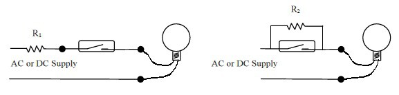
Protection Circuitry for Lamp Loads
Whether the supply is AC or DC, protecting the reed switch contacts can be achieved by limiting the transient current until the lamp filament reaches operating temperature.
Thus a series resistor R1 equal to the supply voltage divided by the maximum reed switch switching current in amps can be used or alternatively a parallel resistor R2 selected to maintain the temperature of the filament sufficiently high that the switch on current does not exceed the capability of the reed switch contacts. Both these protection circuits are shown below.
When selecting resistor R1 or R2 remember to take into account the power rating required to dissipate any heat generated.
Environmental Considerations Chemical Compatibility
Temperature
Knowledge of the expected range of temperature of the liquid and the immediate environment surrounding the liquid level sensor is critical to ensure that the sensor operates reliably.
By careful selection of the materials used in the construction of the sensor it is possible to operate in liquids at up to 300ºC.
When operating at high temperatures, selection of the magnetic materials used is important because there is a tendency to de-magnetise at high temperatures.
Similarly, the reed switches and any electrical conductors, insulation and solder connections must be specified for operation at elevated temperatures also.
Pressure
Some applications require level measurement in a pressurised vessel. In these instances the pressure tends to crush the float and stem of the sensor.
Floats and stems are avail able in a variety of materials which can withstand very high pressures without deforming.
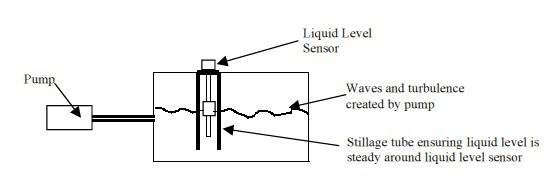
Turbulent Liquid
In applications where a pump may be used to maintain liquid level in a tank the liquid surface can exhibit waves.
Obviously the liquid level sensor float will follow these waves and this can lead to erratic and unnecessary switching. To avoid this a stillage tube is used to protect the sensor from the turbulence. The diagram below illustrates how the stillage tube functions.
Inclusions
Some liquids (slurry for example) contain a high proportion of solid matter. When applying liquid level sensors in these conditions consider the likelihood of these solids interfering with the free movement of the float(s).
In particular if these solids are ferrous there is a positive tendency for them to build up around the float because it is magnetic and will attract any ferrous material.
If the inclusions cannot be prevented or removed then a stillage tube with a wire gauze filter at the bottom could be tried to keep the inclusions away from the sensor.
If none of these precautions are possible then regular cleaning may be the only way to maintain reliable operation.
Chemical Compatibility
The wetted materials used in a liquid level sensor must be compatible with the liquid to be measured.
Care should be exercised in selecting the appropriate materials to avoid contamination of the liquid itself and/or deterioration of the wetted materials of the sensor.
Fortunately chemical compatibility charts are widely available that help designers to select the correct range of materials.
Mounting Arrangements
Liquid Level Sensors may be mounted in a number of ways. Vertically from the roof or floor of the container. Horizontally from the wall. Various standard devices are available to suit many different situations.
In instances where access to the inside of the tank is impossible it is still possible to mount an internal sensor from the outside the only limitation is that imposed by the expanding sealing grommet which if the tank is pressurised beyond a few bar may leak.
Thorne & Derrick are Specialist Distributors of Hazardous Area & Explosion Proof Equipment with IECEx & ATEX Certifications to the onshore and offshore oil, gas, petrochemicals and process industries.
Press Release Date: 02.04.2020 uploaded by Chris Dodds (T&D Sales + Marketing Manager) World’s First Fully Certified ATEX Doors Thorne & Derrick International, the Experts in Equipment for Explosive Atmospheres, today announce the signing of a Commercial Distribution Agreement...
Press Release Date: 04.07.2019 uploaded by Chris Dodds (T&D Sales + Marketing Manager) Category: Stockist Distributor Agreement Announcement Thorne & Derrick International announce that they have signed a Preferred Distributor Agreement with Raytec, the world leading manufacturer of LED...