Emerson together with Thorne & Derrick understand the need for reliable ATEX LED lighting solutions that deliver superior illumination for safer, more productive environments. Whether upgrading a plant’s legacy lighting system or designing a new facility, count on our LED lighting solutions.
Whether upgrading a plant’s legacy lighting system or designing a new facility, you can count on Appleton LED hazardous area lighting solutions.
That is together we are constantly striving to improve your operational performance by protecting you and your equipment, with the latest in today’s LED lighting technology. Appleton™ LED luminaires are designed to deliver superior illumination with unparalleled protection and operate across your facility without incident.
For proper illumination in extreme conditions, you need a lighting manufacturer who engineers their ATEX LED lighting to ensure optimal light dispersion; creating more usable light. From area to task, flood to emergency, the Appleton LED luminaires maximise usable light enabling you to work safely and comfortably.
We also recognise the importance of having LED solutions that are correctly certified for your geographic location and environment. Whether your geography requires ATEX, ATEX/IECEx, NEC or CEC certification, our regulatory involvement, technical expertise and range of LED luminaires solve the challenges of outfitting your facilities.
➡ Thorne & Derrick’s sales engineers together with the support of the Appleton technical team continue to deliver unparalleled innovative advancements in LED lighting, making Emerson the right choice for harsh industrial or hazardous location luminaires.
Luminaires are commonly categorized according to the type of lighting application, lumen level or mounting height. Choosing the right luminaire based on application is critical for providing safe and comfortable light.
Task Lighting
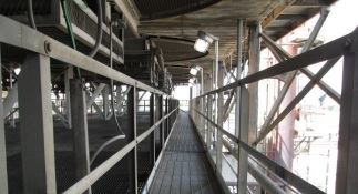
Task lighting provides illumination to accomplish a specific task, such as reading a meter or gauge or safely lighting a walkway. Typical mounting heights are 3 meters (10 feet) or less.
Low Bay or Area Lighting Low bay or area lighting provides illumination of areas with mounting heights up to 6 meters (20 feet). Typical
applications require less than 10,000 lumens, which is closest to a traditional 250 Watt High Intensity Discharge
(HID) luminaire.
High Bay Lighting
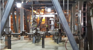
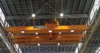
High bay is used to describe lighting applications with mounting heights over 6 meters (20 feet). The locations to be lit normally require greater than 10,000 lumens. Typical applications might include; warehouses, wastewater
treatment facilities, production or processing plants, storages areas or foundries.
Flood Lighting
Flood lighting uses a broad light spread to illuminate a wide area or a focused beam to project light over a great
distance. Mounting heights are usually 6 meters (20 feet) or higher. Flood lighting provides safe and secure lighting. Common applications include tank farms, loading docks and perimeter fence line lighting.
Lighting Services
Lighting Layouts
Together with Emerson’s Lighting Applications Engineers Thorne & Derrick can design a professional solution to accommodate your diverse lighting needs. We design single rooms, whole floors, entire buildings and outdoor projects. Contact us today to find out more.
DIALux™ and the Appleton Plug-In
DIALux is one of the world’s leading software programs for planning, calculating and visualizing light. The complimentary Appleton Plug-In contains IES files for Appleton luminaires. Users have the ability to search for a specific solution according to area classification, light source, mounting type or available globe option. Designers have the freedom to customize their lighting solutions by downloading the free software and the Appleton Plug-In at www.masteringled.com.
Sample The Solutions
Installing a sample is the best method to evaluate a luminaire’s suitability for a particular application or location. Try one out by contacting T&D to request a sample today.
leaders in ATEX Innovation To The Hazardous Area Industries
Thorne & Derrick are leaders in the development and distribution of Product Innovations that deliver significant improvements to clients plant, people and operational safety in the explosive atmosphere industries.
Your proactive problem solvers experienced in succession planning for the replacement of obsolete, non-conformant and legacy equipment in hazardous areas.
Your first-choice provider of innovative and competitive solutions to ensure ATEX & IECEx Compliance for Hazardous Area Electrical, HVAC & Process Instrumentation Equipmentto UK and international projects.
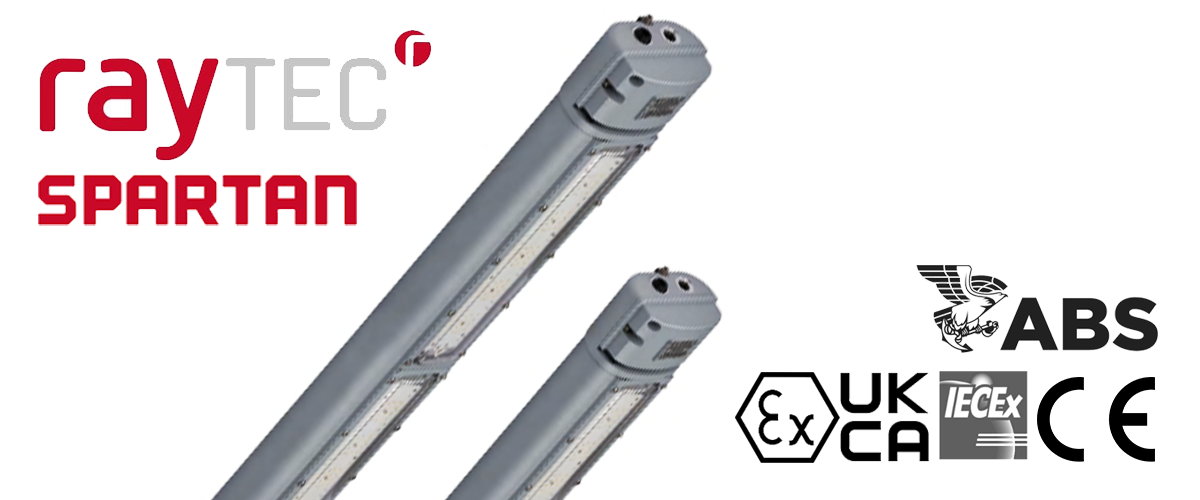
Thorne & Derrick together with Raytec are pleased to invite you to register for their joint webinar. Last year Raytec announced their widely anticipated second generation of SPARTAN Linear Generation IIstocked and distributed by Thorne & Derrick.
The new luminaire is a natural evolution of our existing Linear, providing more performance, even greater levels of durability, and a host of new features and variants which ensures there is a Linear suitable for any application.
You’re invited to take a closer look at the new Hazardous Area Lighting, where we’ll walk you through all the new features, analyse the performance upgrades, and explore all the new variants.
The webinar will cover:
New features & benefits
Performance upgrades
New certification standards
New industrial variants
Logistics & other information
The webinar & product walk-through will take place on Wednesday 6th April 2022.
REGISTER HERE
When:Wednesday 6th April 2022 10.00am BST (London)
Thorne & Derrick International, based in the UK, are Preferred Distributors and Stockists for the Raytec SPARTAN range of ATEX lighting using LED technology for the illumination of hazardous area locations and potentially explosive atmospheres.
Read on more about SPARTAN Linear Generation II range of LED light fittings designed for all new Zone 1 and Zone 2 (ATEX, IEC Ex & UKEX) hazardous area installations or to retrofit existing fluorescent installations below
💡 Did you Know? Thorne & Derrick using latest software provide a FREE LIGHTING DESIGN SERVICE for the specification and supply of ATEX & IECEx Certified light fittings to provide safe and reliable lighting in explosive atmospheres and hazardous area locations.
EXPERTS IN EQUIPMENT FOR EXPLOSIVE ATMOSPHERES
LEADERS IN ATEX INNOVATION TO THE HAZARDOUS AREA INDUSTRIES
Thorne & Derrick are leaders in the development and distribution of Product Innovations that deliver significant improvements to clients plant, people and operational safety in the explosive atmosphere industries.
Your proactive problem solvers experienced in succession planning for the replacement of obsolete, non-conformant and legacy equipment in hazardous areas.
Your first-choice provider of innovative and competitive solutions to ensure ATEX & IECEx Compliance for Hazardous Area Electrical, HVAC & Process Instrumentation Equipment to UK and international projects.
Whitepaper By Appleton August 2018
ATEX LED LIGHT FITTINGS
Light Source Encapsulation
Explosive gas atmospheres present specific risks from ignition caused by electrical component operation and failure. Products used in these applications must offer protective features to insure isolation of potential ignition sources from unstable environmental materials.
For hazardous area lighting applications within zones that experience intermittent exposure to explosive gas atmospheres, prescriptive codes and standards have been established to insure these systems operate in a safe manner.
This paper explores the differences in hazardous exposure protection methods between conventional light sources and solid-state technology, with a review of code requirements and Zone 1 equivalencies that are applicable. Aspects of damage resulting from interaction of light source ignition sources and flammable gaseous materials, and the maintenance,
reliability implications of the protection concepts employed are presented, as they apply to the design, application and continuous service.
This paper also compares the optical and energy utilisation of light sources, and the effects of protection concepts, including flameproof and encapsulated product approaches on product performance initially and over the service life of products.
Background
Hazardous location electrical codes and standards throughout the world are defined by two distinct paths. In North America, a “Class, Division” system is used as the basis for area classification of hazardous (classified) locations. In other parts of the world, explosive atmospheres are addressed through a “Zone” system based on the International Electrotechnical
Commission (IEC) and European Committee for Electrotechnical Standardization (CENELEC) standards.
IECEx/ATEX(1) (ATEX is derived from the French title of the 94/9/EC directive ‘Appareils destinés à être utilisés en ATmosphères EXplosibles’) requirements are defined by two directives. For equipment, ATEX 95, directive 94/9/EC (manufactured prior to April 2016) and 2014/34/EU Article 44 (manufactured after April 2016) defines product requirements, while ATEX 137, directive 99/92EC addresses minimum requirements for workplace safety. The most significant component of IECEx/ATEX directives is that the level of hazard probability is divided into three Zones (See Table 1.0).
In the United States and Canada, methods of protecting hazardous area electrical equipment for different material exposures and hazardous locations are divided into three Classes, and two Divisions. The Classes reflect the type of hazard and the explosive characteristics of the material, while the Divisions reflect the risk of fire or explosion. With a few small differences, these two countries employ similar protection methods and product standards.
While specific requirements differ, the Unites States and Canada have incorporated a similar Zone System for Class I hazardous locations in recent electrical code updates (see Table 2.0 and 4.0). Both systems provide effective solutions for protection used in hazardous locations.
For the purposes of this paper, the focus is on IECEx/ ATEX Zone 1 (which generally includes subsequent coverage of North American Class I, Division 1, and Class I, Zone 1) in defining approaches to equipment protection methodology for hazardous locations in which flammable or explosive gases are likely to be present, either continuously, or intermittently (Table 1.0).
Standards within IECEx/ATEX Zone 1 include specifications for equipment protection concepts within three divisions related to Equipment Protection Level (EPL), (ATEX 1G, 2G, and 3G, corresponding to IECEx EPL Ga, Gb and Gc), which are then included in defining the protection concept utilized (see Table 3.0).
Table 1.0 – Classification Systems by Frequency of Exposure Occurrence
Frequency of Occurrence
North American Class I Division System
IECEx/ATEX Zone System
Hazardous gas, vapor or mist
Continuous– Where an explosive atmosphere consisting of
air and dangerous substances in the form of gas, vapor or mist
is present continuously or for long periods.
Class I, Division 1
Zone 0
Intermittent – Where an explosive atmosphere consisting of
air and dangerous substances in the form of gas, vapor or mist
is likely to occur in normal operation occasionally.
Zone 1
Abnormal Condition – Where an explosive atmosphere
consisting of air and dangerous substances in the form of gas,
vapor or mist is not likely to occur in normal operation or for a
short period only
Class I, Division 2
Zone 2
Table 2.0 Hazardous Area Definition (2)
ATEX equipment group
ATEX equipment category and environment type
Zone classification ATEX/IECEx
Required equipment protection level (EPL)
Class/Zone classification (North America)
Class/Division classification (North America)
II
1G (Very High)
Zone 0
Ga
Class I, Zone 0
Class I, Division 1
2G (High)
Zone 1
Gb
Class I, Zone 1
3G (Normal)
Zone 2
Gc
Class I, Zone 2
Class I, Division 2
Table3.0ATEX/IECExProtection Concepts
Typical Electrical Equipment Exposed to Flammable Gases, Vapors and Mist
Symbol
Type of protection
Basic concept of protection
Suitable for Zones
Typical EPL
EN/IEC Standard
0
1
2
Ga
Gb
Gc
eb
Increased safety
No arcs, sparks or hot surfaces, enclosure IP54 or better
•
•
•
60079-7
d
Flameproof
Containment of the explosion
•
•
•
60079-1
ia
Intrinsic safety
Limitation of spark energy and surface temperatures
•
•
•
•
60079-11
ib
•
•
•
ic
•
•
ma
Encapsulation
Keep the flammable substances out
•
•
•
60079-2
mb
•
•
•
mc
•
•
Table 4.0 Protection Concepts for North America and Canada
Typical Lighting and Electrical Equipment Exposed to Flammable Gases, Vapors and Mist
U.S.Code
CanadianCode
Type of protection
Basic concept of protection
Class I, Division
Class I, Zone
U.S.Standard
CanadianStandard
1
2
0
1
2
AEx e
Ex e
Increased safety
No arcs, sparks or hot surfaces
•
•
•
ISA 60079-7
CSA E60079-7
AEx d
Ex d
Flameproof
Contain the explosion and extinguish the flame
•
•
•
ISA 60079-1/ UL 1203/FM 3615
CSA 60079-1
AEx ia
EX ia
Intrinsic safety
Limit energy of sparks and surface temperature
•
•
•
•
ISA 60079-11/ FM 3616
CSA E60079-11
AEx ib
EX ib
•
•
•
ISA 60079-15
CSA E60079-15
AEx nL
EX nL
Limited energy
—
•
ISA 60079-15
CSA E60079-11
AEx m
Ex m
Encapsulated
Keep flammable gas out
•
•
•
ISA 60079-18
CSA E60079-18
AEx ma
N/A
•
•
•
•
Not Applicable
AEx mb
•
•
•
Light Source Technology Factors
Light source technology has a profound effect on protection concepts. Light sources, such as HID, halogen and fluorescent present several challenges to protection from exposure to hazardous gases.
Due to short service life, glass lamp technologies require frequent service of spent lamps over the life of a product. Further, internal arc sources and high temperature filaments that exceed the flash point temperatures of all gases within Zone 1 applications, demand complete isolation of the lamp and its surrounding compartment from atmospheric gases present. HID and halogen technologies also produce high temperatures that demand increases in luminaire cavities to reduce surface temperatures.
Due to the frequency of access for regular lamp replacement, risks of failure of compartment seals is increased as the product is serviced over its lifetime.
LED technology, due to relatively low surface temperature, and extremely long service life, provides opportunities to incorporate protection methods, such as encapsulation, to reduce exposure risks while significantly reducing the cavities of luminaires themselves. Further, due to the high efficacy of LED sources, the total energy and subsequent related heat, is reduced, presenting lower external luminaire surface temperatures, with significantly smaller luminaire cavities (and subsequent external dimensions).
Table 5.0 illustrates the characteristics of the light source, and how these impact protection approaches.
Table 5.0 Light Source Comparison
Source
Arc hazard
Surface temperature hazard
Luminaire cavity requirement (surface temperature reduction)
Maintenance interval * (hours)
Maintenance access/ failure risk
Potential for encapsulation
Halogen/Incandescent
Moderate
High
Large
500 – 3,000
High
n/a
Metal Halide
High
Very High
Large
5,000 – 20,000
High
n/a
HPS
High
Very High
Large
5,000 – 30,000
High
n/a
Fluorescent
Moderate
Moderate
Moderate
5,000 – 30,000
High
n/a
LED
None
Low
Small
70,000-100,000
Minimal
Light source and electronics
* Light source maintenance interval based on range of hours to first failure (infant mortality) of source to longest expected full service life expected before maintenance is required to restore product to functional service.
Solid State Technologies (LED) Impact On
Protection Approach
LED light sources present several opportunities to reduce luminaire size and weight. The characteristics of LED light sources and supporting electronic components are particularly well suited to the application of encapsulation to isolate both electrical connections and heat sources from intrusion of gases.
Optical encapsulants can also include features that eliminate, or enhance optical performance, reducing product mass and scale, resulting in lower profile designs in compact enclosures. Further, the lower operating temperatures of LED sources allow the use of polymer materials for lenses and optical enclosures.
Encapsulation provides additional advantages in prevention of explosion or damage, application in >55°C (131°F) ambient environments, and provides for common construction beyond Zone 1, including Zone 2 as well as dust exposure Zones 21 and 22.
Encapsulation Approach, Materials, and Design Considerations
Typically, encapsulation of electronic components for LED products is identical to other encapsulated electrical and electronic components, using common potting polymer systems, such as epoxies, silicones, and polyurethanes, which can serve a dual purpose of providing thermal conductivity, or isolation depending on product design requirements.
For optical encapsulation, the use of silicone and siloxane hybrid materials is most common. High quality optically clear encapsulants suited to Zone 1 encapsulation, typically deliver 90% to 95% transmission, with long service life at temperatures up to 200°C (392°F) without yellowing for the service life of the LEDs encapsulated(2). These encapsulants may be used over LED arrays with no other optical components, molded into optical forms to act as lenses and/or diffusers, or around and under discrete silicone, polycarbonate, or Poly(methyl methacrylate) (PMMA) optical components.
Approaches to encapsulation vary between product designs. The most economical approach is to encapsulate electronics and LEDs into luminaire bodies, essentially sealing the interior into a non- serviceable assembly that is permanently sealed. This approach requires the entire luminaire to be replaced at the end of service life. Modular designs utilize individually encapsulated components attached within the housing, that are able to be replaced at the end of service life without necessitating complete luminaire replacement.
In either construction, there remains space within the luminaire that remains un-encapsulated. For this reason, while encapsulation provides additional protection in Zone 1 applications, luminaires utilizing encapsulation or encapsulated modules will also include additional areas within the product covered under other equipment protection levels (EPLs).
This includes the cavity not filled with encapsulants, wire connection compartments, and wireways between components that are not otherwise covered. However, the utilization of Ex mb (encapsulation) reduces the requirement of protection of these uncovered cavities from Ex d (Flameproof)to Ex eb (Increased Safety) to fully satisfy the requirements of Zone 1 application.
Figure 1.0 below illustrates the combination of EPLs applied to a luminaire that employs encapsulated modules within a Zone 1 design.
Figure 1.0 – Example Composite Protection Method Diagram
While encapsulation provides additional protection within luminaire construction, which can be used to reduce product size and weight, the connection of the luminaire, and the housing surrounding the encapsulated modules must be considered and designed under eb, or “Increased Safety” protection methods. Encapsulation of components or modules does not replace this requirement.
Luminance Effects and Efficiency
The comparison of total luminaire efficiency between conventional flameproof (Ex d protection method) products (HID, fluorescent and LED) and LED products that utilize encapsulation for additional protection requires consideration of several variables. While large reflectors and high efficiency optics may produce a theoretical advantage over encapsulated products, the advantage is very small, considering that modern encapsulants deliver transmission of >90%.
Additionally, integration of optical features into the encapsulant itself, over sealing a molded separate optic onto the LED array with silicone, reduces light loss.
This integrated approach produces optical performance that is equivalent to non-encapsulated luminaire designs.
Optical systems for HID sources generally account for greater losses in efficacy than encapsulant materials impart on LED sources, while LED optics (both encapsulated and bonded) tend to be more efficient and suffer less degradation over time due to dirt accumulation, surface degradation due to aging and maintenance contact, and surface area accumulation of debris, scratches, and material degradation.
Additionally, LEDs produce significantly higher efficacy than any other light source. This produces a margin of tolerable loss for application of protection methods, such as encapsulation, to realize gains in luminaire design, reduced scale, streamlining appearance, thermal management, and reducing weight.
Testing Requirements
Testing of encapsulated components within luminaires is no different than any other protection method. All materials utilized in products intended for Zone 1 applications must be fully tested, including employment of HALT (Highly Accelerated Life Test) methods, salt spray testing, as well as quality controls to insure product integrity remains over the intended service life.
While there are no universal or established HALT parameters for testing encapsulated luminaires, the following test parameters could be considered a baseline for establishing product performance under conditional extremes:
Strife test: increase ambient until failure (105°C (221°F) or more) (4 hours at each level)
Thermal Shock Test: -40°C to 125°C (-40°F to 257°F), 30 minutes each, 250 cycles
High Temperature Steady State Test: LED T-case 105C, 1000 hours
Low Temperature Steady State Test: -55°C (-67°F), turn on, 500 hours
Temperature and Humidity Stress Test: 85°C (185°F), RH: 85%
For products utilizing encapsulation of LED sources within optical systems, additional consideration of adhesion of encapsulants to LED arrays, optical components (where employed), and degradation of optical performance over the service life of the sources utilized, is required. The unique interface of light source components, optics and encapsulant materials, present differences in coefficient of expansion conditions that must be tested over the entire operating temperature and humidity range anticipated for the intended application.
Conclusion
The opportunity to employ the protection concept of encapsulation presented by solid-state technology is a significant improvement over conventional flameproofing, in all areas of product design including physical construction, optical design and energy efficiency, through use of efficient LED light sources over conventional lamps (which cannot be encapsulated), and protection from damage caused by interaction of light sources with flammable materials
in Zone 1 applications. Encapsulation delivers Ex mb protection, eliminating the need for flameproof construction, while also providing specific light beam pattern generation, with a resulting increase in total system performance (efficacy and precision of illumination delivery) over a reflector/lamp flameproof fixture.
The Appleton Lighting Retrofit Calculator helps users visualise savings accomplished by retrofitting their current lighting system to an Appleton LED solution. Calculate maintenance, energy and environmental savings achieved by upgrading to Emerson’s Appleton LED luminaires with this interactive tool.
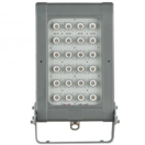
Lighting | Zone 1 & Zone 2 Hazardous Area Lighting EX ATEX Certified
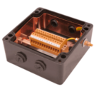
Junction Boxes | Zone 1 & Zone 2 Hazardous Area Junction Boxes EX ATEX Certified
Control Stations | Zone 1 & Zone 2 Hazardous Area Control Stations EX ATEX Certified
EXPERTS IN EQUIPMENT FOR EXPLOSIVE ATMOSPHERES
leaders in ATEX Innovation To The Hazardous Area Industries
Thorne & Derrick are leaders in the development and distribution of Product Innovations that deliver significant improvements to clients plant, people and operational safety in the explosive atmosphere industries.
Your proactive problem solvers experienced in succession planning for the replacement of obsolete, non-conformant and legacy equipment in hazardous areas.
Your first-choice provider of innovative and competitive solutions to ensure ATEX & IECEx Compliance for Hazardous Area Electrical, HVAC & Process Instrumentation Equipmentto UK and international projects.
UK Stocks | International Delivery | Zone 1 (21) & Zone 2 (22) Hazardous Area Light Fittings From Stock
Raytec have recently launched their Linear Generation II – an upgrade on the original SPARTAN Linear where they’ve been able to increase power, performance, and durability across the Linear range. The upgrade has a host of new features and variants to suit all your hazardous area lighting requirements in a range of different applications.
Did you Know?– The Linear is the most popular lighting product in the SPARTAN range so Raytec decided to build on the most important key features and carry out a comprehensive review on the design, performance and range of the current product offering.
The Spartan Linear is now delivering up to 7,000lm / 142 lumens per watt, and for the first time is available with a choice of beam angles (see below) which are ideal for a wide range of applications.
Choice of Optics – More beam angles = fewer luminaires per installation
Performance Upgrades?
What Do They Really Mean?
While this all sounds great on paper, what do these performance upgrades mean in the real world? In this article, Raytec use their award-winning lighting design service to demonstrate the improvements; We’ll look at three different scenarios and compare the existing Linear (Gen 1) products side-by-side with the new Linear Generation II (Gen II).
Utilise Fewer Luminaires
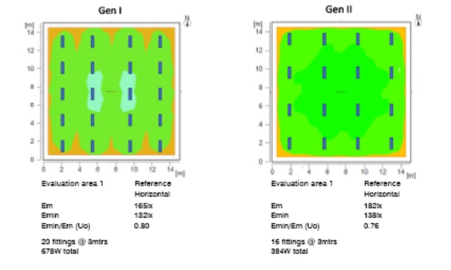
The first design we’ll look at is a basic 14x14m square internal room, where we’ll be aiming to achieve an average of 150lx.
The Gen I design (left) requires an installation of 20 luminaires to achieve the target light levels, with the result coming out at 165lx. If we compare this to the Gen II design (right), for the same installation we only need 16 luminaires – and despite using fewer fittings, there’s actually more light on the ground, with an average of 182 lux.
In addition to the improved performance, there’ll also be a significant reduction in energy consumption – a 45% saving, largely thanks to a new, more efficient driver. With fewer luminaires required, there’s also a capital saving to be made of around 17.
For larger installations, the extent of these savings will grow exponentially and help end-users to significantly reduce both their initial outlay and ongoing running costs.
Mount Higher
In the next example, we’ll look at the impact of Linear Gen II’s improved performance has on mounting heights. Below, the Gen I design (left) has the luminaires mounted at 6m, whereas the Gen II design (right) which has the mounting height increased to 10m.
Despite being mounted 4m higher, Linear Gen II is delivering almost identical results to the Gen I luminaires mounted at 6m.
In short, Linear’s increase in power means it’s now possible to significantly increase the height in which the luminaire is mounted. It also brings the performance of the luminaire into the territory of low-bay style fittings, but with the advantage of being far more cost effective, and being available with emergency battery back-up. This brings lots of new opportunities to end-users.
Greater Flexibility
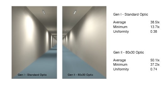
Linear is now available with a choice of different beam patterns thanks to a range of secondary optics. While this is beneficial to a host of applications, the new 80×30 beam angle is particularly beneficial for aisle or walkway applications, offering big improvements over the single beam angle available with the existing Linear;
Gen I & Gen II Optic Comparison
In the Gen I design (left) the results are noticeably patchy. A lot of the light is being wasted against the side wall, leaving dark areas along the floor as you continue down the corridor. If we compare that with the same design using the new Linear Gen II (utilising the 80×30 optic), we can see that the floor has a much more even light distribution with far less light wasted against the wall.
This is reflected by a big improvement in the average and minimum lux levels, as well as a far better uniformity rating when using Linear Gen II and it’s 80×30 beam angle.
Use Smaller Luminaires
In some scenarios, Linear’s performance upgrade and new optics can even allow end-users to utilise a smaller sized variant.
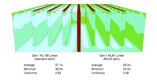
Below are two identical scenarios; a warehouse installation where the lighting goal is to illuminate the aisles between the racking. On the left is a design using a Linear WL168 Gen I luminaire (designed as a direct replacement for a traditional 4ft/2x36W fluorescent), and on the right is the same design using Gen II Linear, but a smaller SPARTAN WL84 fitting (designed to replace a traditional 2ft/2x18W fluorescent).
While the larger Gen I fitting has a greater light output on paper, within this application we can see a lot of the light is being wasted against the racking either side of the aisle (especially towards the top of the racking). In contrast, looking at the Gen II (right), the beauty of the new optics means that more of the light can be targeted straight down to the ground, between the aisle, exactly where it’s needed.
The upshot of this is, despite using a smaller sized Linear on the Gen II design, both are delivering the same performance on the ground. Both solutions deliver an average of 57 lux from the same 12-meter mounting height.
While end-users looking to ATEXretrofit existing fluorescents may still have to consider existing infrastructure, such as cabling and bracketry, the ability to use a smaller luminaire could be particularly beneficial for new installations. Utilising a smaller Linear will again help to reduce the initial capital outlay as well as ongoing running costs.
As we’ve demonstrated, the performance upgrade to Linear Generation II brings significant benefits when it comes to real-world applications. It provides end users with greater levels of flexibility in terms of the types of applications and the areas where the luminaire can be used effectively, all while helping to reduce costs and energy consumption.
How Can T&D Help?
Lighting Designs & Surveys
Thorne & Derrick hold large UK stocks of ATEX light fittings, ensuring fast overnight delivery to your plant.
Using latest software our FREE Lighting Design Service supports the upgrade from fluorescent to LED lighting focussed on maximised light output, optimised energy consumption with reliable and safe certification for explosion protection concepts in Zone 1 and Zone 2 hazardous area zones and workplaces.
Contact our technical sales team today who will assist with all your winter lighting requirements.
Raytec SPARTAN
Thorne & Derrick International, based in the UK, are Preferred Distributors and Stockists for the Raytec SPARTAN range of ATEX lighting using LED technology for the illumination of hazardous area locations and potentially explosive atmospheres.
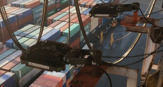
SPARTAN is a full range of Ex LED luminaires and lighting approved for all ATEX and IEC Ex Zone 1 and Zone 2 hazardous area environments, including UL /CSA C1D2 installations. The hazardous area lighting products are designed for the most extreme environments – Flood, Linear, Bulkhead, Bay and Crane luminaires with emergency and industrial lighting versions are also available from Thorne & Derrick International.
EXPERTS IN EQUIPMENT FOR EXPLOSIVE ATMOSPHERES
leaders in ATEX Innovation To The Hazardous Area Industries
Thorne & Derrick are leaders in the development and distribution of Product Innovations that deliver significant improvements to clients plant, people and operational safety in the explosive atmosphere industries.
Your proactive problem solvers experienced in succession planning for the replacement of obsolete, non-conformant and legacy equipment in hazardous areas.
Your first-choice provider of innovative and competitive solutions to ensure ATEX & IECEx Compliance for Hazardous Area Electrical, HVAC & Process Instrumentation Equipmentto UK and international projects.
ATEX Explosion Hazards Limited has spent nearly 50 years improving the health & safety of workers at work, in explosive atmospheres, in various industries.
In their recent white paper, ATEX Explosion Hazards Limited explore the language of explosion safety. From the earliest recorded dust explosion in Mr Giacomelli’s bakery in the Piedmont area of Italy in 1785, through explosions in UK flour mills a century later, to the language used in legislation of the present day.
Every industry has its own language, terms and acronyms. Below is a Glossary of the common terms in use in the Explosion industry today and how they are employed in current directives. As well as a short overview of the main directives and legislative instruments that govern our industry as well as the testing and statistics that are used and how to interpret them.
Italy 1785
The earliest recorded Dust Explosion happened in Mr Giacomelli’s bakery in the Piedmont area in Italy on 14th December, 1785. A boy shovelling flour by naked candlelight from one level of a warehouse to another had his face and arms scorched in the blast, which blew out windows and released flames into the street.
Another boy, seeing the flames coming towards him, jumped off a scaffold and broke his leg. The accident was reported to be due to the dryness of the corn, as there had not been any rain for the last 5 to 6 months in the Piedmont area!
Figure 2.1 Dust Explosion in the Process Industries
UK Explosions in Flour Mills, 1888
A century later in the United Kingdom, a mill owner called Reynolds issued the following instructions to his staff; Within recent years, several disastrous explosions have occurred in flour mills, resulting in loss of life and destruction of much valuable property.
As all flour mills are liable to such explosions at any moment, it is desirable that the workmen should understand the chief causes of danger and how they may be best avoided. Explosions may be caused when any dust is mixed with air and a naked light brought into contact with the mixture. Flour sharps, stive wheat dust, smut-dust or sweepings will all explode either singly or when mixed.
It is therefore necessary of all who work in the mill that the following precautions shall be most carefully observed.
1. Never stir or mix up loose dust while gas is lit.
2. Never examine a machine with naked light.
3. NEVER ENTER ANY SIVE OR DUST ROOM WITH NAKED LIGHT
4. Never strike matches or smoke about the premises.
5. Where is necessary to sweep or dust at night, do it as quietly as possible
to avoid agitating the dust.
6. Always use closed lamps within the mill
7. Report a leakage of gas directly you find it.
We trust all our workmen will see the necessity for extreme care and the use of lights of all kinds. Should any man exhibit carelessness in this respect after this warning, we shall be obliged to dismiss him.
J Reynolds & Co.
October 1888
Irish Factories Act, 1955
“In the case of a process giving rise to dust of such a character and to such an extent as to be liable to explode on ignition, then, unless the plant is so constructed as to withstand the pressure likely to be produced by any such explosion, all practical steps shall be taken to restrict the spread of the effects of such an explosion by the provision, in connection with the plant, of chokes, baffles, and vents, or other effective appliances”.
EU July 2006
Organisations in the EU must follow the directives, to protect employees from explosion risk in areas with an explosive atmosphere.
This ATEX directive consists of two EU Directives:
1. ATEX 153 or (ATEX 137) Directive 99/92/EC – The responsibility of the User:
This Directive aims at establishing and harmonising minimum requirements for improving the safety and health of workers potentially at risk from explosive atmospheres.
2. 114 Directive 2014/34/EU – Harmonised requirements for the Manufacturer to sell to the User: The Directive of the European Parliament and the Council of Ministers on 26 February
2014 relating to Free trade of goods and the harmonisation of the laws of the Member States relating to equipment and protective systems intended for use in potentially explosive atmospheres.
UK Version
The UK version of the EU directives is known as the Dangerous Substances and Explosive Atmospheres Regulations (DSEAR). DSEAR requires employers to assess the risks of fires and explosions that may be caused by dangerous substances in the workplace & complements the requirement to manage risks under the Management of Health and Safety at Work Regulations.
DSEAR relates to assessments to how people may be affected by dangerous substances and explosive atmospheres. ATEX relates to assessments associated with the equipment that will be used in areas that may be affected by dangerous substances and explosive atmospheres.
CE is Conformity European but UKCA stands for UK Conformity Assessment. As of 1 January 2021, UKCA marking was to replace CE marking.
● NFPA 61: Standard for the Prevention of Fires and Dust Explosions in Agricultural and Food Processing Facilities
● NFPA 68: Standard on Explosion Protection by Deflagration Venting
● NFPA 69: Standard on Explosion Prevention Systems
● NFPA 85: Boiler and Combustion Systems Hazards Code
● NFPA 484: Standard for Combustible Metals
● NFPA 652: Standard on the Fundamentals of Combustible Dust
● NFPA 654: Standard for the Prevention of Fire and Dust Explosions from the Manufacturing, Processing, and Handling of Combustible Particulate Solids
● NFPA 655: Standard for Prevention of Sulfur Fires and Explosions
● NFPA 664: Standard for the Prevention of Fires and Explosions in Wood Processing and Woodworking Facilities
Glossary of Terms:
BZ Number: A product train of width 2 cm and length 4 cm is deposited on a ceramic plate and a glowing platinum wire inserted in an attempt to ignite the dust. After successful
ignition, the severity of the subsequent burning is observed.
Test Result
Class
Reference
No ignition
No spreading of fire
1
Table salt
Brief ignition, rapid extinction
2
Tartaric acid
Localised combustion or glowing with practically no spreading
3
D + Lactose
Glowing withou sparks (smoldering) or slow decomposition without flames
Fire spreads
4
H – acid, tabaco
Burning fireworks or slow quiet burning flames
5
Sulphur
Very rapid combustion with flame propagation or rapid decomposition without flame
6
Black powder
Dust Hazard Analysis (DHA): Understand your hazardous materials, systematically evaluate processes risks, and manage by either administrative or engineering controls.
Explosion Proof: Explosion-proof or flame-proof equipment is sealed and rugged, such that it will not ignite a hazardous atmosphere, despite any sparks or explosion within.
Control Systems and Hazard and Operability (CHAZOP): Study more than HAZOP (qv.), control systems and individual failures of the processes.
Computational Fluid Dynamics (CFD): Software that simulates the dispersion of hazardous materials, fire and explosion.
Failure Mode & Effects Analysis (FMEA): Anticipate, identify and detect potential points of failure of design and consequence.
Fault Tree Analysis (FTA): FTA is a top-down, deductive failure analysis in which an undesired state of a system is analysed using Boolean logic, to combine a series of lower-level events.
Gap Analysis gives organisations an overview of the progress they have made in implementing each of the Standard’s controls.
Hazard Identification (HAZID): Risk analysis for early detection of hazards performed at the earliest stage of project development.
HAZLOC: In electrical and safety engineering, hazardous locations (HazLoc) are places where fire or explosion hazards may exist.
HAZOP: verify and test control and operations in your facility are robust and inherently safe, “as far as reasonably practicable.”
Intrinsic Safety: Intrinsic safety designs equipment to operate using minimal energy, insufficient to cause ignition.
Layers of Protection Analysis (LOPA): A method used to evaluate high-consequence scenarios determining if the combination of probability, of occurrence and severity of consequences, meets a company’s risk tolerance.
Occupational Safety and Health Administration (OSHA): A federal agency of the United States that regulates workplace safety and health.
Process Hazard Analysis (PHA): Potentially hazardous materials, to identify and evaluate dangers, control and mitigate by implementing safety measures.
Process Safety Management (PSM): interrelated approaches to managing hazards associated with the process industries and is intended to reduce the frequency and severity of incidents resulting from releases of chemicals and other energy sources.
Risk Assessment (RA): Risk assessments give organisations an indication of the threats facing them, how likely it is that each of those threats will occur and how severe the damage.
Statistics:
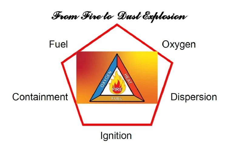
Going back to our basic science class, we have the Fire triangle but we need to add containment and dispersion for a dust explosion.
When presenting these articles we usually present Statistics:
2017
2018
2019
2020
Fires
169
213
250
165
Explosions
68
68
74
60
Injuries
163
78
118
88
Fatalities
13
23
8
10
So there are more fires than explosions. In the EU we assume about 2 explosions per day in industry, but not all incidents are reported. What are we most interested in, when considering process safety:
Life Safety, Plant Safety and Mitigation
Material Properties:
How do you know that a material is dangerous unless you test it?
Group A/B (Vertical Tube) Test: Essentially, the dust under test is dispersed in air at ambient temperatures, past a source of ignition and observations of fame propagation made by the
operative.
● Group A is a dust, which is able to ignite and propagate flame
● Group B is a dust, which does not propagate flame
Further testing is required for Group B samples if handled at elevated temperatures >110 degree C.
So what terms do we use to define appropriate sample: particles size (less than 500 micron, potentially explosive, fines less than 100 micron or test sample 63 micron), distribution
usually greater than 30 to 60 g/m3 (you cannot see the hand on the end of your arm), shape (fibre or granular).
Explosion violence falls at higher moisture contents: 0-5% has little effect, 5-10% decreases sensitivity and >25% particles unlikely to stay in suspension.
Where to collect your sample: Horizontal surfaces, girders, floor or inside plant i.e. inside ductwork or inside dust collectors/filters.
Material Safety Data Sheet:
Does the supplier offer an appropriate MSDS? These data sheets are frequently short on specifics:
Minimum Ignition Temperature MIT (cloud)of a dust suspension is the lowest temperature at which it will ignite spontaneously and propagate same. This MIT value is particularly
relevant to problems involving relatively large heated areas of plant e.g. surfaces of dryers, mills, electrical equipment, etc.
Minimum Ignition Temperature: MIT (LIT) 5mm Layer: The test determines the minimum temperature of a prescribed hot surface, which will result in the decomposition and/or
ignition of a layer of powder of specified thickness. The test is particularly relevant to industrial equipment with hot surfaces, on which dust deposits may form. Thicker layers will invalidate the T rating of equipment and may cause ignition.
Dust Minimum Ignition Energy (MIE) Dust Cloud of a dust suspension is the lowest energy at which ignition and flame propagation away from the spark kernel occurs – the value being particularly relevant to identifying potential electrostatic ignition hazards.
Two circuits are employed – capacitive (for electrostatic ignition) and inductive (for friction spark ignition).
In general, three ranges are defined as significant:
Walking across the carpet and touching a metal doorknob can be up to 4 mJ.
A dust is more ignitable at an elevated temperature, i.e. the Minimum Ignition Energy (MIE) is lower.
Concentration Lower Explosion Level (LEL for gases and vapours)or Minimum Explosible Concentration (MEC for powders) is typically of the order 45g/m3 and 30-60 g/m3 respectively. The Upper Explosion Level (UEL) not as clearly defined for powders, but usually is >1000g/m3.
LOC: maximum oxygen concentration in a mixture of a flammable substance and air and an inert gas, in which an explosion will not occur, determined under specified test conditions.
Explosion Characteristics: Kst in bar m/s & Pmax in barg: Although the methods above are relevant for prevention of flame and explosions, to confirm the quantitative assessment of a design for explosion protection, you will need to conduct an actual controlled dust explosion in either the 20 litre or 1m3 test apparatus.
Material
P/max
Kst bar m/s
Methane
8.4
58
Hydrogen
8.2
503
Sugar
8.0
80
Coal
7.7
85
Starch
9.4
150
Cellulose
10.0
160
Milk Powder
8.2
147
Dextrin
8.7
200
Aluminium
11.5
555
As shown, dust explosion pressures can reach the same as gases/vapours and some metal dusts can be as dangerous as Hydrogen.
The speed of the flame may be constant but the surface grows exponentially emitting more heat faster in a confined space, this creates pressure which may eventually break the confinement. To design a protection system these terms are essential. Remember the bigger the vessel, the longer it takes to get to its Pmax, unless the plant strength fails first!
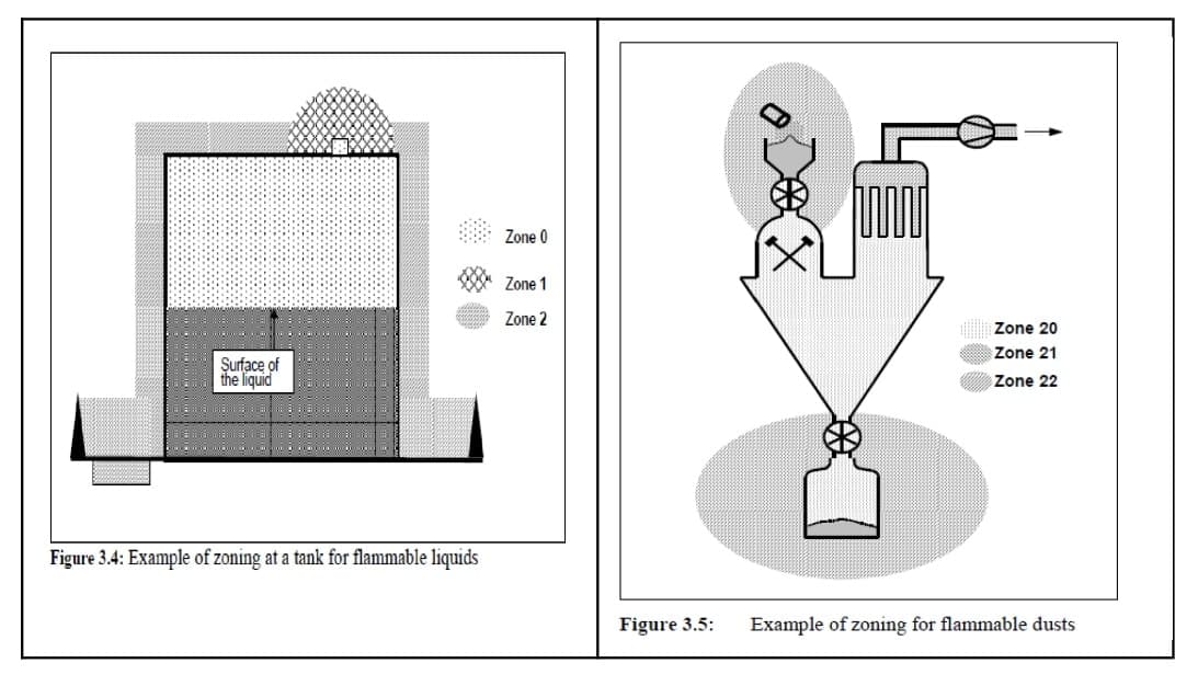
Equipment & Hazardous Area Classification
A place in which an explosive atmosphere in the form of a cloud of combustible dust in air is not likely to occur in normal operation (perform their intended function within their design
parameters) but, if it does occur, will persist for a short period only – e.g. outlets from cyclones, clean-side of dust filters, etc.
Historically, the following probability values have been used for guidance (with gases/vapours) and these are commonly applied to solids handling also.
1. Continuous Source (> 1000 hrs. yr-1) yields a Zone 0 / 20 with Equipment Cat 1G/D
2. Primary Source (10 – 1000 hrs. yr-1) yields a Zone 1 / 21 with Equipment Cat 2G/D
3. Secondary Source (<10 hrs. yr-1) yields a Zone 2 / 22 with Equipment Cat 3G/D
You must install the appropriate equipment to the designated Zone
Marking of Equipment – Directive 94/9/EC (Annex II, 1.0.5)
Name/address manufacturer
CE marking + if appropriate notified body number
designation of series or type
Serial number, year of construction
Ex symbol + EEx
Category (M1 / M2 / 1 / 2 / 3) for equipment-group II, ‘G’ (gas) and/or ‘D’ (dust)
Explosion / Ignition protection symbol + (if appropriate) Gas group
Temperature Class or Temperature
Example: EEx 2 G d IIA T4
Certification ensures that the equipment or protective system is fit for its intended purpose and that adequate information is supplied with it, to ensure that it can be used safely.
Explosion Protection Document (EPD):
The EPD must be drawn up prior to the commencement of work and be revised when the workplace, work equipment or organization of the work undergoes significant changes, extensions or conversions.
The employer may combine existing risk assessments, documents or other equivalent reports and incorporate them into the explosion protection document.
The ATEX Directive allows the Explosion Protection Document to be either a separate document or part of a combined safety report and as a whole must cover both technical and
organisational or procedural aspects of explosion prevention and protection. Thus for the majority of process plant, it is recommended that these two aspects be separated and dealt with in different documents.
More than 2000 incidents of gas, mist and dust/air atmospheres occur annually in Europe, causing injuries, loss in production, plant damage and even death. This is not acceptable
and the introduction of the ATEX & DSEAR regulations should be welcomed.
There are many organisations suddenly offering products and services, which can help you through this, but make sure they are reputable, with a history in explosion prevention and
protection.
The ATEX exercise should be programmed and carried out by the employers, with their workers, to make industry a safer and more profitable experience. To do this it helps if you understand the language of explosion safety today.
Declan Barry, MD of ATEX Explosion Hazards Ltd, entered the Explosion business in 1987. His primary objective is to make industry safer by installing appropriate explosion protection solutions with full back up services. He believes strongly that people cause explosions not equipment, yet there is an over-emphasis in industry on area classification, testing and equipment selection, when he believes that the lack of continuous education and training is the primary cause of dust explosions.
EXPERTS IN EQUIPMENT FOR EXPLOSIVE ATMOSPHERES
LEADERS IN ATEX INNOVATION TO THE HAZARDOUS AREA INDUSTRIES
Thorne & Derrick are leaders in the development and distribution of Product Innovations that deliver significant improvements to clients plant, people and operational safety in the explosive atmosphere industries.
Your proactive problem solvers experienced in succession planning for the replacement of obsolete, non-conformant and legacy equipment in hazardous areas.
Your first-choice provider of innovative and competitive solutions to ensure ATEX & IECEx Compliance for Hazardous Area Electrical, HVAC & Process Instrumentation Equipment to UK and international projects.
Press Release Date: 02.04.2020 uploaded by Chris Dodds (T&D Sales + Marketing Manager) World’s First Fully Certified ATEX Doors Thorne & Derrick International, the Experts in Equipment for Explosive Atmospheres, today announce the signing of a Commercial Distribution Agreement...
Press Release Date: 04.07.2019 uploaded by Chris Dodds (T&D Sales + Marketing Manager) Category: Stockist Distributor Agreement Announcement Thorne & Derrick International announce that they have signed a Preferred Distributor Agreement with Raytec, the world leading manufacturer of LED...