Declan Barry has an objective to make the industry safe by installing the appropriate explosion protection solutions to industry with full back up services. With 42 years of experience providing Explosion Hazard Services to the process industry, ATEX Explosion Hazards Ltd have a wide range of expertise within their group of companies.
This is the seventh in a series of eight articles, which aim to help you establish a simple basis of safety in your plant and dispel some of the myths associated with process and safety risk assessments.
ATEX SAFETY Protection
The ATEX Safety Protection concept is based on the assumption that ignition and an explosion (gas, vapour, mist or dust) may arise and steps need to be taken to mitigate the effects, thereby safeguarding personnel and (as far as practicable) maintaining the integrity of the plant. The options available are dependent on the plant vessels / layout and the characteristics of the materials. There is a choice of two designs. An Explosion Pressure Resistant Design (EPRD) does not allow for any deformation of the vessel whereas an Explosion Pressure Shock Resistant Design (EPSRD) does i.e. deformation is acceptable, but not total failure.
Explosion Pressure Relief
Explosion pressure relief is perhaps the most common but essentially there is a ‘loss of containment’ i.e. process material and/or flame will be emitted from the protected vessel during the explosion. Conversely, explosion suppression and total explosion pressure containment systems do not give rise to a release of process material.
Venting
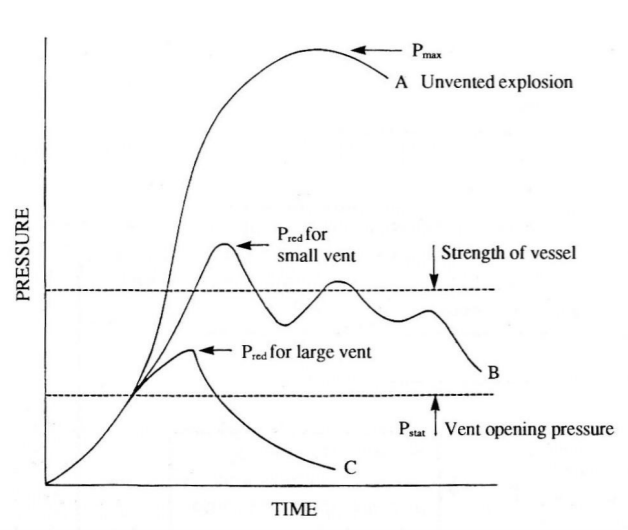
Explosion venting is a protective measure preventing unacceptable high explosion pressure build-up inside vessels / enclosures. Normally explosion venting is applied such that the maximum reduced explosion pressure (Pred,max) does not exceed the known design pressure of the vessel; the lower the vent opening pressure (Pstat) and the larger the vent area, the lower the reduced explosion pressure. Moreover, ALL parts of the enclosure, including valves, access ports, ductwork, etc. exposed to the explosion pressure, must be taken into account when estimating the design pressure of the vessel – this is to ensure that the relief of the explosion pressure is accomplished in a controlled manner.
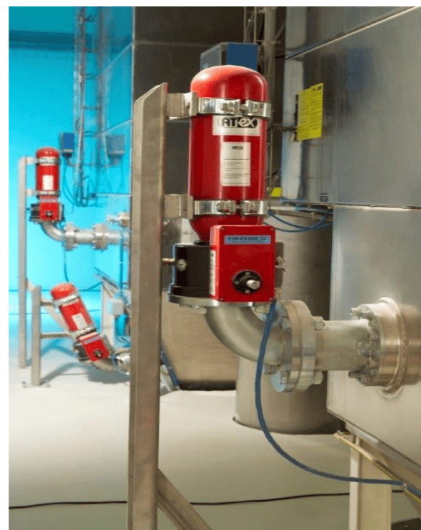
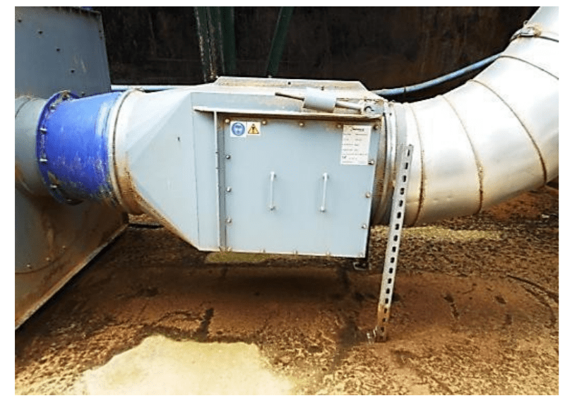
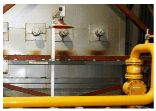
Venting does not prevent an explosion, it limits the explosion pressure. Hence, flame and pressure effects outside the enclosure and flying debris must be anticipated and accounted for. To preclude this, flameless venting devices (depicted below) may be used – this form of venting is particularly useful for plant sited in (or close to) the middle of the work area; otherwise, long vent ducts would be required to safely vent the explosion outside the confines of the building.
Explosion Supression
As mentioned above, explosion suppression does provide containment of the ‘reduced explosion pressure’ (Pred).
This is achieved by detection of the incipient explosion i.e. in its early stages. Whilst the combustion is taking place (most of the time quite rapidly over a few milliseconds), once detected, suppressant is injected in to the growing fireball to quench the flame.
The predominant effect is absorption of heat, temperature reduction and stoppage of flame transmission. Once again, ALL parts / components of the vessel must be taken into account when estimating the design pressure.
In practice, the quantity of suppressant (number of suppressors) and their location will depend on the violence of the explosion (Pred and Kst from dust testing), the geometry of the vessel and its design pressure.
Explosion Pressure Containment
With the exception of some milling operations, as a safety concept, explosion pressure containment is less common. This is due to the high design strength needed – typically of the order 8 – 10 bar.g for dust explosion containment. Common gases and hydrocarbons have lower peak explosion pressures of about 6 – 8 bar.g.
It is important to recognise, however, that ANY explosion protection system MUST cover upstream and downstream interconnections i.e. it is imperative to provide isolation to prevent propagation of burning particles, flame and pressure.
Isolation
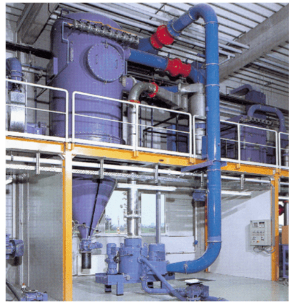
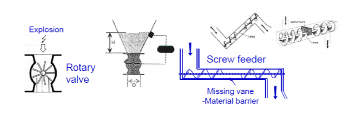
Isolation can take the form of an ATEX certified rotary valve or active of passive slam-shut (rapid action) valve, chemical extinguishing barrier, product choke, etc. as described in prEN 15089 Explosion Isolation Systems.
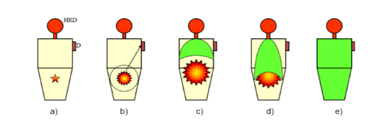
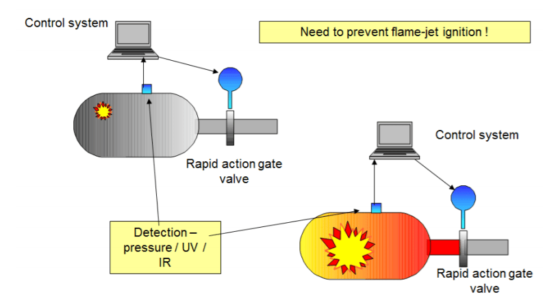
For complete isolation (e.g. by use of a slam-shut valve), the design pressure must be applied up to the isolation device. Hence, any ducting or pipework up to this point would need to withstand the maximum anticipated pressure i.e. Pred or Pmax. A typical arrangement is shown in the schematic below. The closure time of the rapid action valve, together with the response time of the detection/control system and flame speed, denes the required minimum distance (L) from the source of the explosion – typically L > 5000 mm.
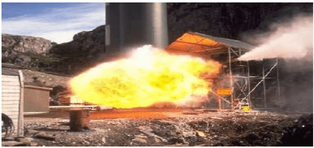
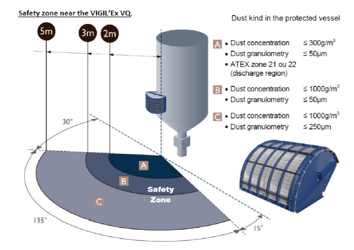
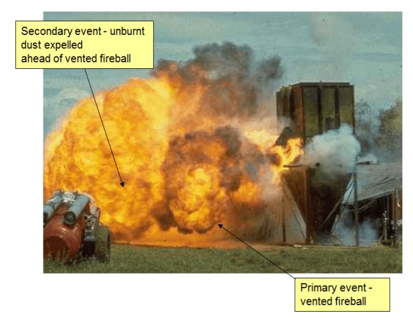
A vented explosion must discharge to a safe area and often, this requires the use of a vent duct. The action of venting, in most cases, will be accompanied by ejection of burned and unburned gases and flames and measures must be taken to ensure that nearby plant and personnel will not be at risk from the vented fireball. It is important also to note that a vent duct will increase the backpressure during the relief process requiring a greater pressure resistance for equipment and vessels.
Flames ejecting from a vent opening will spread in all directions but especially in the main lateral venting direction due to inertia. Moreover, the flames will represent a thermal radiation hazard. In certain cases, a deflector plate (depicted below) can be used to limit the length of the ejected flame.
In addition, if the vent is situated in the side wall, the recoil force on the enclosure must be considered in the design. Also, as shown in the photograph above, unburned dust can be ejected ahead of the fireball during venting increasing external thermal radiation and overpressure effects.
As part of the isolation concept, equipment must be shut down automatically, in the event of an explosion, to prevent transfer of burning material, etc. With venting, this is normally achieved by sensors fitted to the vent panel. Of course, this should not result in frequent spurious shutdowns, since some will find ways of by-passing the problem – by means of wood and scaffolding poles to keep vent doors shut, for example, as shown. The CORRECT course of action would have been to examine why the explosion doors keep opening! When fitting explosion protection, from a process viewpoint, it is important to think about any repercussions. One example is the use of Rotary Valves for explosion isolation purposes as this is often contentious due to the likely ‘wear rates’ and the need to maintain certain tolerances (in particular, the gap between the blades and the casing).
Another example is the use of Flap-Valves in dust laden ductwork. The on-going ‘user obligations’ regarding inspection and maintenance of such items is not always appreciated.
For example, periodic inspection checks must be undertaken to ensure that the explosion isolation capability does not deteriorate (e.g. due to corrosion, abrasion, dust built up on the flap, dust build up inside the body of the flap valve).
The positioning of explosion vents on Dust Filters is important too, to ensure that the internal filter membranes do not obstruct (compromise) the protection.
Vent panels sited close to membranes can result in an increase in the ‘reduced explosion pressure’ (Pred value) and over-pressurisation of the vessel – the filter bags can be blown out of the vent on activation. A further consideration is that of providing automatic re suppression since Filters can be terminally damaged by secondary thermal stresses due to burning bags or product, following the explosion.
This is the seventh in a series of eight articles, which aim to help you establish a simple basis of safety in your plant and dispel some of the myths associated with process and safety risk assessments. The next article in the series is entitled ‘Management Procedures’ and covers the precautions we need to take as part of our managerial responsibilities to mitigate the risk of injury or fatality (to Plant Operators or members of the public), the Statutory Requirements (Legal Obligations) which we must adhere to and the consequences when things go wrong.
LEADERS IN ATEX INNOVATION TO THE HAZARDOUS AREA INDUSTRIES
Thorne & Derrick are leaders in the development and distribution of Product Innovations that deliver significant improvements to clients plant, people and operational safety in the explosive atmosphere industries.
Your proactive problem solvers experienced in succession planning for the replacement of obsolete, non-conformant and legacy equipment in hazardous areas.
Your first-choice provider of innovative and competitive solutions to ensure ATEX & IECEx Compliance for Hazardous Area Electrical, HVAC & Process Instrumentation Equipment to UK and international projects.
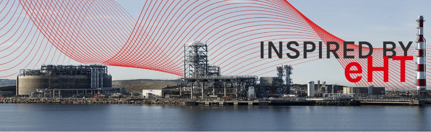
The LNG tanks comprise of double containers, where the inner contains LNG and the outer container contains insulation materials. In LNG storage the pressure and temperature within the tank will continue to rise unless regulated this is where an electrical trace heating system for hazardous areas is able to maintain the exact temperature during the entire gas liquefaction process.
To achieve liquification, the gas must be cooled down to -160 °C. LNG occupies only 1/600th of the volume of natural gas. So liquifying is an economic option for storage and transport. Linde was assigned by the Norwegian Skangass AS to build a LNG plant at Stavanger in Norway, including a LNG storage tank with a diameter of approximately 50 m.
Because of the -160 °C inside the storage tank, frost can occur around and under the tank and in the foundation of the plant, causing frost heave cracking. This can pose a serious risk to safe operation. A trace heating system prevents this by keeping the structure‘s at 5 °C. Reliability is the key requirement, so Eltherm engineers developed a redundant system with was chosen.
Eltherm – Heat Tracing Solutions
Heat Tracing Cables for LNG Tanks
Exact temperature maintenance during the entire gas liquefaction process
Reliable function thanks to redundant design
Simple, safe operation with power and control system
Trace heating systems for hazardous areas covered by ATEX approval
Repair and easy maintenance of PTFE insulated trace heaters
Turnkey service including complete engineering, design, installation and commissioning
50 heating circuits in normal operations and 40 circuits in essential generator mode allow one system to be repaired in the case of unexpected failure, while the other maintains normal function. In addition to the foundation heating a ring-heater beneath the ring wall was installed to prevent freezing. The scope of supply included engineering and design, installation and commissioning as well as power and control systems.
The pipeline network of the LNG plant with all drums and pumps is heated to +10° C for freeze protection. Also, process temperatures between 15 °C and 140 °C are maintained to ensure that the gas liquefaction process runs smoothly and safely.
Linde AG is a global leader in natural gas liquefaction plants and consulted Eltherm engineering to develop a custom build solution for the Stavanger LNG plant in Norway.
Frost protection on the foundation slab required 16 heating circuits, 12 in the foundation and 4 under the ring wall. To take account of the highly corrosive ambient conditions, the ELKM-AG-N trace heater with its robust fluoropolymer insulation was employed.
It is chemically resistant even at high temperatures and is certified for hazardous areas (Ex area). Additionally to the heating system, Eltherm provided the complete control room for power and control. Strong emphasis is placed on energy efficiency and running cost reduction. An under-run alarm with 2 °C and an excess alarm at 15 °C ensures that the liquefaction process is never disturbed.
Thorne & Derrick specialise in providing specialist heating for industrial and hazardous areas including Eltherm’s heat tracing cables and heated hoses.
ELTHERM INDUSTRIAL & HAZARDOUS AREA HEATING
Eltherm heating products provide freeze protection, temperature maintenance and temperature control ranges of up to 1000°C and are used in many industries and applications from oil and gas to utilities and power generation. Eltherm products are manufactured to the highest hazardous area specifications including ATEX and IECEx for heating pipes, hoses, drums, vessels and IBC’s.
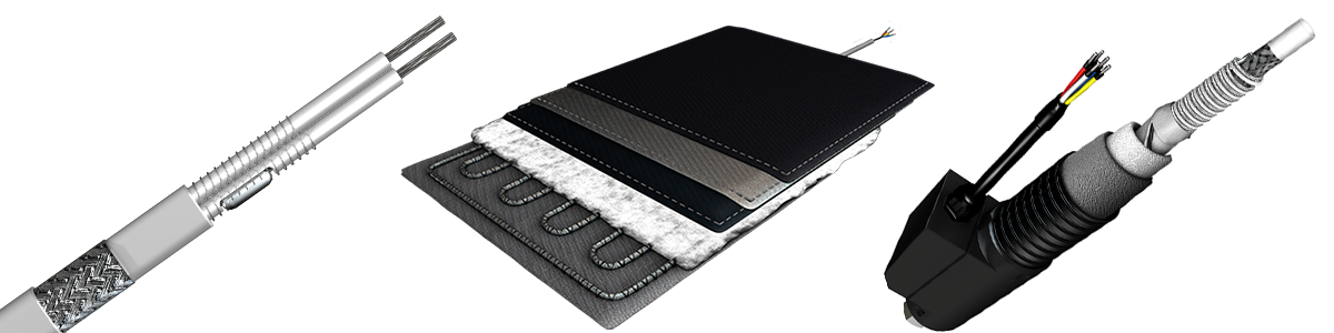
Eltherm self regulating heat trace cable provides frost protection and maintains product viscosity in pipes, tanks, drums and vessels
Electrical Heating Specialists
Thorne & Derrick International, based in the UK, can specify and supply from stock an extensive range of Electrical Heating Equipment for industrial and process heating applications – this includes temperature maintenance and frost protection (Winterisation) products for pipework, valves, IBC’s, drums, hoses, tanks and vessels. We produce custom silicone heaters for rapid and high temperature heat-up of complex shapes and surfaces – from concept, design to the delivery of standard or bespoke heaters on the shortest lead times. From the largest UK heat tracing cable stocks we deliver Electric Trace Heating Systems for pipework frost protection, ramp heating, roof/gutter snow melting and de-icing – enquire about our in-house design service.
EXPERTS IN WINTERISATION SOLUTIONS FOR INDUSTRIAL & HAZARDOUS AREA ENVIRONMENTS
Thorne & Derrick hold the largest UK stocks of frost protection & winterisation equipment to help keep your plant and personnel operational during the winter months.
Thorne & Derrick understand that prolonged periods of low ambient temperatures can bring operations to a standstill costing thousands of pounds in lost downtime.
Experts in heating solutions for use in industrial & explosive atmospheres, Thorne & Derrick have the knowledge & expertise to help clients prevent unnecessary down time this winter.
We can provide overnight delivery of Trace Heating Cables at the most competitive prices to guarantee frost protection of your pipelines and mechanical services.| Ask About Our Heat Trace Design Service.
💡 Contact us today and our skilled and friendly team can provide technical support as well as reliable, fit for purpose and compliant solutions to suit your exact requirements.
➡See our Winterisation blog TOP PICKS, including our most read articles about Trace Heating and the requirement for electrical heating products and systems to combat and mitigate Winter weather effects.
Declan Barry has an objective to make the industry safe by installing the appropriate explosion protection solutions to industry with full back up services. With 42 years of experience providing Explosion Hazard Services to the process industry, ATEX Explosion Hazards Ltd have a wide range of expertise within their group of companies.
This is the sixth in a series of eight articles, which aim to help you establish a simple basis of safety in your plant and dispel some of the myths associated with process and safety risk assessments.
ATEX Safety Prevention
As mentioned in the first ‘introductory’ article, prevention of the formation of an explosive atmosphere, including the application of appropriate ventilation, is an acceptable approach to control of risk.
Prevention techniques can be simple, dilution for example, equally applicable to certain types of solvent handling operations and evaporative Ovens / Dryers as dust extraction systems.
The question is – can we under all normal and abnormal operations?control (i.e. eliminate) one of the THREE basic components for combustion?
Codes of practice, for Dryers and Ovens in which flammable substances are released, set out basic design criteria (dilution of the vapour). This is aimed at processes where the flammable VOC concentration exceeds 3 % of the Lower Explosive Limit.
Essentially, the ‘maximum admissible quantity of flammable substance’ needs to be determined and controlled against the ‘minimum forced ventilation flowrate’ in order to maintain conditions below the ‘maximum admissible concentration’ below the LEL. This includes any short-term operations. Indeed, a formal HAZOP study, which examines ALL of the conditions which can lead to the formation of extensive flammable atmospheres inside plant equipment, should be undertaken to allow the necessary ventilation rates to be determined.
Dilution
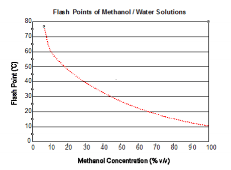
Following on from the first Introductory Article, water miscible solvents can be made ‘safer’ simply by adding water, to an alcohol for example. If the maximum ambient temperature is (say) 25 ˚C, using a 5K safety factor, concentrations up to 40 % v/v would be permissible.
Dilution of the liquid is sometimes employed where solvents are used for cleaning purposes, thereby eliminating the formation of hazardous areas (and the potential for ignition) both inside and outside equipment.
Ventilation
Ventilation (or rather Extraction) can be employed to dilute airborne dust, in a spray coating operation for example.
Typically, a primary source of release will exist within the confines of the spray / extraction hood (i.e. ‘concentration gradients’ will exist between the source [spray head] and the ventilated surroundings, allowing localised flammable atmospheres to occur) but, given the correct level of ventilation, flammable atmospheres (hazardous areas) should not extend in to the extraction system.
The necessary extraction rates are determined from the spray rates. For example, at a mass feed rate of 355 g.min-1 per gun at 100 % and 24 gun operation, assuming 50 % overspray, the mass feed rate to the extraction system is 256 kg.hr-1.
As a rule, the maximum concentration within the ductwork should be 25 % MEC (typically between 10 – 100 g.m-3) and in view of the fact that the airflow through the extraction ductwork forms part of an explosion safety system, this should be monitored or (at least) afforded a flow switch to indicate poor performance i.e. reduced ow.
Ventilation also plays a key ‘preventative’ role in gas- red systems e.g. Boilers, Burners, etc. Efficient and effective ventilation can render a Boiler House as Zone 2 (NE) i.e. of negligible extent.
Gas detection has a role to play also, when interlocked to the supply and thereby limiting the persistence of the hazardous area. The siting of the detector head is critical, however; governed by neighbouring equipment and local air movement due to thermal gradients and forced or natural ventilation.
Smoke tests (or children’s’ ‘Bubbles’ – YES, BUBBLES) can be used to check that there is free movement of air around the equipment i.e. to ensure that the proposed ventilation is effective at the point of interest and the Zone 2 NE (negligible extent) designation can be upheld.
Inerting
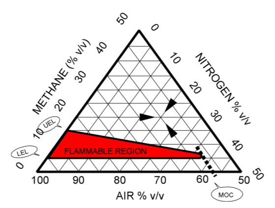
Inerting is another preventative technique but here, we are controlling the Oxidant concentration rather than the fuel. The diagram (below) expresses the flammability characteristics (or ‘envelope’) for methane, depicting lower and upper explosive limits and the ‘nose’ of the curve at which the MOC occurs. The principle of the flammability envelope also holds for vapours and airborne dusts i.e. as the oxygen concentration is reduced, the lower and upper flammability limits converge to a point where flame propagation cannot be sustained.
Inert gas blanketing or purging is commonly used as the sole basis of safety. Thus, it is imperative to maintain the reduced oxygen level inside the processing environment whilst the potential source of ignition may be present
It can be seen that a reduction in oxygen content does not change the lower limit value but markedly reduces the upper limit. This is because oxygen is in excess at the lower flammable limit.
Generally, a safety factor is applied to the required oxygen level (MOC or LOC [Limiting Oxygen Concentration]) to take account of changes in environmental conditions and also, to allow for inaccuracies that may arise when monitoring or sampling the internal atmosphere – a safety factor of 2.0 – 3.0% below the limiting value is recommended.
Literature information (NFPA 69 Explosion Prevention Systems Appendix C Table C-1 – National Fire Protection Association) indicates an MOC value of 9.5 % by volume for Toluene, where nitrogen is the purge gas. Hence, the design basis value would be a maximum of 5 % oxygen by volume under normal running conditions with shut down at 7.5 % oxygen by volume.
It must be borne in mind that MOC values like flammability limits, are pressure and temperature dependent. Also, gases other than nitrogen can be used for inerting purposes e.g. halogenated compounds, water vapour, carbon dioxide, etc. and their efficiency is dependent upon their gaseous specific heat capacity.
Inert gas blanketing/purging is used in many industries as a Basis of Safety e.g. Metal Purification, Pharmaceuticals, Coal Handling Plant (Mills), etc.
Even ‘partial inerting’ has benefits. This is where the concentration of the oxidant lies above the MOC value but below the prevailing atmospheric level. Flame propagation can still occur but at a reduced rate, depending on the extent of oxygen depletion. In such cases, the gas/vapour-air or dust-air mixtures will lie within the flammable envelope but at a point where the explosive limits are closing.
This influences not only explosion severity but also ignition sensitivity – combustion through the mixture can still occur but the explosion effects will be reduced. Ignition sensitivity will decrease also. A reduction in oxygen content can result in marked increases in both hot surface ignition temperature and minimum ignition energy.
As discussed in previous Articles, we can base safety on ‘Elimination of Ignition Sources’ IF the basis for the hazardous area classification (Zoning) is sound, ALL equipment within the Zones is correctly ATEX certified AND we don’t introduce ‘user’ or process intrinsic ignition sources such as static electricity, smoulders, hot surfaces, etc.
Control of Ignition Sources
We cannot stress this enough – without knowing the ignition sensitivity of the material (be it gas, vapour, mist or dust), we cannot assess the ignition potential with any accuracy. Likewise, we need to know the extent of the hazardous Zones accurately so we can assess which operations / equipment can give rise to the ignition sources.
Intrinsic ignition sources are those which exist solely due to the operation, for example:
So, in essence, ignition prevention depends on how thorough you are AND how competent you are in identifying sources of ignition which might become EFFECTIVE, i.e. capable of igniting the flammable atmosphere under the prevailing process conditions (taking in to account temperature, concentration, moisture level, particle size, etc.).
But the consequences can be huge if you get it wrong!
This is the sixth in a series of eight articles, which aim to help you establish a simple basis of safety in your plant and dispel some of the myths associated with process and safety risk assessments. The next article in the series is entitled ‘Protection’ and covers the steps needed protect personnel and plant by mitigating the effects of an ignition or explosion if one happens.
LEADERS IN ATEX INNOVATION TO THE HAZARDOUS AREA INDUSTRIES
Thorne & Derrick are leaders in the development and distribution of Product Innovations that deliver significant improvements to clients plant, people and operational safety in the explosive atmosphere industries.
Your proactive problem solvers experienced in succession planning for the replacement of obsolete, non-conformant and legacy equipment in hazardous areas.
Your first-choice provider of innovative and competitive solutions to ensure ATEX & IECEx Compliance for Hazardous Area Electrical, HVAC & Process Instrumentation Equipment to UK and international projects.
Declan Barry has an objective to make the industry safe by installing the appropriate explosion protection solutions to industry with full back up services. With 42 years of experience providing Explosion Hazard Services to the process industry, ATEX Explosion Hazards Ltd have a wide range of expertise within their group of companies.
This is the fifth in a series of eight articles, which aim to help you establish a simple basis of safety in your plant and dispel some of the myths associated with process and safety risk assessments.
ATEX Safety
Static Ignition & Thermal Instability
Static electricity is part of everyday life and is generated when materials come in to contact with each other and then separate i.e. electrostatic charging occurs at the interface. The phenomenon is known as a ‘contact electrification’ and this gives rise to a ‘streaming’ or charging current.
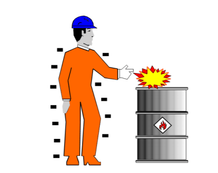
Potential electrostatic charging hazards are shown in the following images and include fluid ow in pipework, drum charging operations, walking across a floor, pouring powders, film transport rollers, spraying, etc.
The electric field produced can give rise to different types of discharge, with differing energy levels. The highest charging currents arise from the use of electrically insulating materials (e.g. PTFE lined equipment, Poly-Tubs, plastic sheeting and insulating (low conductivity) liquids such as Toluene, n-Hexane and many others.
Operatives isolated from earth via their footwear or the flooring can become charged unknowingly, simply by standing within an electrostatic field.
For example, at rest, humans are likely to be charge neutral i.e. no significant excess positive or negative charge. However, if they stand next to a highly charged surface (e.g. negatively charged FIBC), the charges on their body will ‘polarise’ i.e. the residual negative charges will be repelled and the positive charges attracted. Whilst in this position, if the person touches an earthed item, the free (negative) charges will ow to earth and as he or she walks away, they will be left with net positive charge, which is a potential source of static ignition.
Charge generation per se is not the issue; the problem is the accumulation of charge because it can create a source of static ignition.
The most basic precaution against electrostatic ignition is earthing – the structure of the plant and associated vessels/equipment are a potential source of electrostatic charge accumulation and therefore, must be earthed to avoid this risk.
All metal items and fittings (e.g. funnels, metal spirals in flexible LEV trunking, etc.) should be in good contact with each other and with earth. For example, Blo-line / Morris couplings have an integral earthing strip (as shown in the photo above) to ensure electrical continuity through the coupling and along the pipework.
Electrical continuity checks should be made before equipment is brought into use and following any maintenance work.
Frequently, however, earthing failures are evident during audits e.g. unattached / ungrounded metal reinforcing helices in flexible trunking, grilles in loading chutes, etc.
The requirements for resistance levels are essentially those normally used by electrical engineers i.e. LESS THAN 10 to earth. In practice, higher resistances may be used (up to 106 Ω) but only where the reason for the high resistance is known and controlled.
Static Ignition
Types Of Discharge
Spark: Occurs between two conductors (the plasma
channel is over the entire gap)
Corona: Point discharge with no plasma channel
Brush: Occurs between a charged non-conducting
surface and a (rounded) earthed conductor or
electrode
Propagating Brush: Polarised insulating sheets of
very high charge density
Cone: Occurs from highly charged, high resistivity
granular materials
People
People who are insulated from earth (by their footwear or the flooring) can easily acquire and retain an electrostatic charge. If the MIE of the flammable atmosphere is lower than 30 mJ, consideration needs to be given to grounding personnel i.e. use of ‘charge dissipative’ footwear and flooring. In addition, clothing should be as close fitting and should not be removed or unfastened within the hazardous area.
Insulating Plastics
Insulating plastics can present a risk of static ignition in zoned areas, also. ‘Brush discharges’ with energies up to 4 mJ can occur from charged insulating surfaces and this is well in excess of the minimum required for static ignition of low ash point solvents (e.g. Acetone, Toluene, Methanol, etc.) and sensitive airborne powders.
Thus, the exposed surface areas of insulating surfaces need to be restricted, as shown below.
Restrictions on Surface Area (cm2) – Sheets
Gas type G
Group IIA
Group IIB
Group IIC
0
50
25
4
1
100
100
20
2
No limit
No limit
No limit
For example, high resistivity plastics exceeding 100 sq.cm in area cannot be used with IIA or IIB solvents in Zone 1 areas, unless it can be shown that charge generation (or incendive discharges) will not arise even in the case of likely malfunctions. Clearly, this excludes all but the smallest of plastic items.
To preclude highly energetic ‘propagating brush discharges’, special types of FIBC are required. Type A bags (which have no dissipative properties and high breakdown strengths) should NOT be used with explosible powders.
A – No special requirements
B – Breakdown FIBC wall < 4 kV
C – Resistance to earth from any location <
100 M.Ω
D – Interwoven conductive threads not
connected together
Thus, an electrostatic hazard assessment requires a systematic study of where (and the levels of) charge that can be generated, whether it can accumulate, the type and energy of the discharge and the ignition sensitivity of the flammable atmosphere.
Thermal instability
General guidance for risk control is specified in DSEAR Section 6.4 (Risk Reduction) and one of the key elements is ‘Avoid Adverse Conditions’ Essentially, in heated equipment such as Dryers, Hot Boxes, etc.), this relates to the identification and control of areas where hot dry material can collect (Dryer inlets/outlets, Mechanical Conveyors, Mills, etc.).
In most cases, small scale tests such as DTA or DSC? will not be sufficient; Diffusion Cells, Aerated Cell or Air Over Layer tests are preferred since the availability of air during self-heating can have a profound effect. The key features are the onset temperature of self heating Tonset, the points at which the exotherm becomes marked Tmarked (> 5 K/min) and rapid Trapid (> 50 K/min).
Thermal stability test results can indicate significant self-heating hazards e.g. smouldering nests inside bulked product, smoulders on ledges inside Dryers, etc. Some materials exhibit relatively low exotherm onset temperatures from about 130 ºC and high peak temperature of > 700 ºC, even on the small scale.
However, these tests are still for screening purposes because they don’t allow the effect of scale to be determined. Where exothermic activity near the process operating temperature is likely, further ‘Basket Tests’ will be required to allow safe operating temperatures to be quantified. The tests are run isothermally in wire baskets of different size.
The effect of scale is predicted by plotting scale (volume/surface area) against the reciprocal self-heat temperature TC (K). An example is given as follows:
The self-heat onset temperature will increase as the surface area of the bulked material increases. For example, if a material starts to self-heat at 93 ºC as a 1 m3 mass, thermal predictions may show that as a 50 cm thick layer, the onset would be nearer 107 ºC due to greater cooling by the larger surface area.
Thermal instability can also occur in fibrous insulation. The potential static ignition / re hazard arises from auto-oxidation of insulation – a gradual exothermic oxidation of combustible material, accompanied by the generation of heat. Hence, auto-oxidation needs to be controlled whenever there is a possibility of insulation being contaminated, particularly by oils at elevated temperatures
Auto-oxidation and escalation in temperature is exacerbated by the inherent insulation (low thermal conductivity) properties and high surface area. Hence, it is often prudent to use a closed-cell type of insulation on hot oil systems, particularly around joints, known leakage points, etc. since this type of insulation is not prone to oil seepage or wetting.
NOTE: Great care is needed when removing contaminated lagging as this too can spontaneously ignite. Oil contaminated lagging should be removed only under a HOT WORK permit.
LEADERS IN ATEX INNOVATION TO THE HAZARDOUS AREA INDUSTRIES
Thorne & Derrick are leaders in the development and distribution of Product Innovations that deliver significant improvements to clients plant, people and operational safety in the explosive atmosphere industries.
Your proactive problem solvers experienced in succession planning for the replacement of obsolete, non-conformant and legacy equipment in hazardous areas.
Your first-choice provider of innovative and competitive solutions to ensure ATEX & IECEx Compliance for Hazardous Area Electrical, HVAC & Process Instrumentation Equipment to UK and international projects.
Declan Barry has an objective to make the industry safe by installing the appropriate explosion protection solutions to industry with full back up services. With 42 years of experience providing Explosion Hazard Services to the process industry, ATEX Explosion Hazards Ltd have a wide range of expertise within their group of companies.
This is the fourth in a series of eight articles, which aim to help you establish a simple basis of safety in your plant and dispel some of the myths associated with process and safety risk assessments.
ATEX Safety Sources Of Ignition
EU ‘ATmosphere EXplosif’ (ATEX) Directives require manufacturers to provide safe (certified) equipment for use in hazardous areas under the Equipment Directive previously referred to as ATEX 95 now 114. Similarly, users of equipment are required to assess both the likelihood of forming a hazardous area and the risks from ignition (identification and control) under the Use Directive previously referred to as ATEX 137 now 153.
Standard BS EN 1127-1:2011 ‘Explosive Atmospheres – Explosion Prevention and Protection Part 1. Basic concepts and methodology’ distinguishes between 13 types of ignition source:
Common
Less Common
Mechanically generated sparks
Stray currents & cathodic protection
Hot surfaces (e.g. binding friction)
Electromagnetic elds (9 – 300 GHz)
Flames and hot gases
Electromagnetic radiation (3 x 10¹¹ to 3 x 10¹⁵ Hz or wavelength range from 1000 µm to 0.1 µm (optical spectrum)
Electrical apparatus
Ionising radiation
Static electricity
Ultrasonics
Lightning
Adiabatic compression & shock waves
Chemical reactions (inc. spont. ignition)
This article covers some of the more common sources. Static electricity and chemical reaction / thermal instability will be covered in a separate article.
Equipment Category
Explosive Atmosphere
Control of ‘effective’ ignition sources
Cat. 1G / D
Zone 0 / 20
No sources of ignition in normal operation, during expected malfunctions AND during rare malfunctions
Cat. 2G / D
Zone 1 / 21
No sources of ignition in normal operation AND during expected malfunctions
Cat. 3G / D
Zone 2 / 22
No sources of ignition in normal operation
The table above shows the general philosophy behind matching the required level of ignition control to the likelihood of forming a flammable mixture. In practice, some of the above can be avoided, for example, by management procedures or by specification of special (i.e. suitable) equipment. However, many potential sources of ignition are present by virtue of the plant hardware, materials in use or mode of operation and as such, are inherent to the specific process and in need of control.
Source of ignition | Mechanical Sparks
Ignition risks can arise when two hardened materials come into contact with force resulting glancing impact and friction sparks.
With certain materials, the impact energy can initiate an exothermic reaction (i.e. the Thermite reaction associated with aluminium, titanium, magnesium, zirconium and their alloys), resulting in highly incendive sparks of ‘white hot’ appearance. Thermite friction sparks (particularly with rusty steel and aluminium) are known to be extremely energetic and capable of igniting many flammable gases, vapours, mists and dusts.
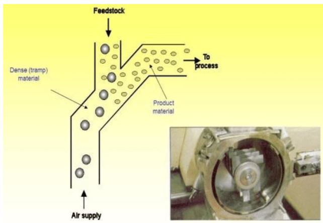
Sometimes, pneumatic separators are used in the feed supply to remove ‘debris’, upstream from a Mill, for example; a good option where metal detection may not be 100 % reliable.
In reality, the ignition risk from any form of spark depends on the sensitivity of the fuel-air mixture. More stringent requirements are needed for Group IIB and IIC gases/vapours, because of their greater sensitivity, compared to Group IIA materials.
Research has been undertaken to evaluate the ignition hazard with respect to airborne dusts and this, together with similar work in Germany, has led to a better understanding of friction spark ignition capability e.g. the effect of the level of thrust at the point of impact.
In many instances, steel-on-steel friction and grinding sparks do not give cause for concern, due to the relatively slow rotational speeds of equipment i.e. if contact occurs at all, it is likely to result in increased surface temperatures rather than multiple sparks.
Therefore, potential sources of ignition can be eliminated by maintaining low circumferential (contact) velocities i.e. below 1 m.s-1.
Hot Surfaces
In accordance with BS EN 1127-1:1998 ‘Explosive Atmospheres – Explosion Prevention and Protection’, for gases, vapours and mists, the maximum surface temperature must not exceed:
80% of the AIT value in C (even in the case of rare malfunctions) for Category 1 equipment (i.e. Zone 0 areas)
80% of the AIT value in C (during normal operation and in the case of rare malfunctions) for Category 2 equipment (i.e. Zone 1 areas)
100% of the AIT value in C (during normal operation) for Category 3 equipment (i.e. Zone 2 areas)
Hot surfaces can arise in many situations, both intentionally (e.g. drying operations) or spuriously (e.g. binding friction from Screw Conveyors and similar mechanised equipment, in this case the 1m/s does not apply. Hot particles from exhausts need to be eliminated in zoned areas, also.
Control of drying temperatures is of particular importance. To eliminate hot particles from direct red systems, it is necessary to:
Clean / filtered air if re-circulated
Clean burners regularly
Fit 3mm mesh on air inlet to restrict large (glowing) particles
The Dryer inlet and outlet temperatures must be restricted also. Typical values for an explosion protected Dryer are:
50K below MIT cloud value
50K below MIT cloud value 10-20K below AirOver-Layer exotherm onset temp
Flames & Hot Gases
The most obvious risk of flame arises from unauthorised ‘hot-work’ and clearly procedures should be in place to ensure that this cannot arise – a near-miss was witnessed when an operator was sweeping dust from one side of a large sieve screen whilst welding work was being undertaken on the opposite side.
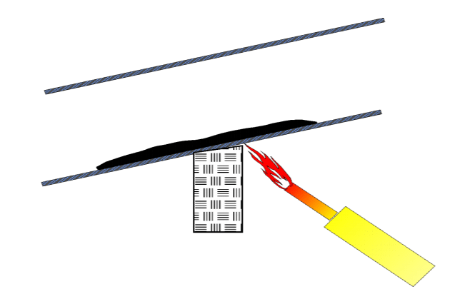
Hot work is a well-known cause of dust explosions and this activity needs special consideration. Instances are given in the open literature where (unknowingly) smouldering material has arisen inside the plant item, which then resulted in ignition on start-up.
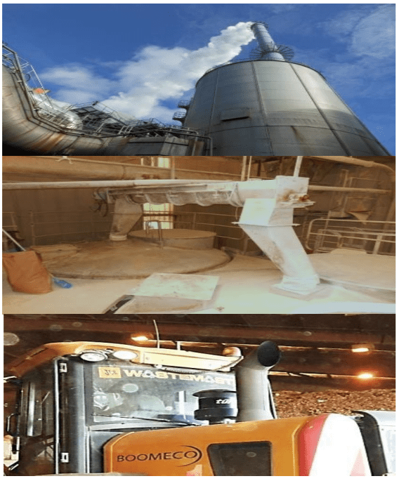
In bulk storage areas, burning embers from the engine of trucks should be precluded by means of a certified flame arrester. Provided the necessary maintenance and inspection regimes, associated with this device (and any other heated surfaces e.g. engine block, manifold, etc.) are adhered to, this form of ignition hazard can be eliminated.
Electrical Equipment
Electrical apparatus used within the hazardous areas should be certified for the Gas Group (gases, vapours and mists/sprays) and the Temperature Class (‘T’ rating).
The maximum surface temperature of equipment (‘T’ rating) is the highest temperature attained in service under the most adverse operating conditions (but within the recognised tolerance) by any part or surface of the equipment which would be able to produce an ignition of the surrounding potentially explosive atmosphere.
The ‘T’ rating of equipment intended for use in flammable atmospheres and based on a max. ambient temperature of 40 °C, is listed as follows:
Temperature Class
Max. Surface Temperature (C)
T1
450
T2
300
T3
200
T4
135
T5
100
T6
85
The criteria for selection of equipment is:
less than 2/3rds MITcloud
AND
more than 75K below MIT5mm layer
Using ‘typical’ wood nes as an example :
MITcloud : 470 * 2/3 = 313 ºC
MIT5mmlayer : 260 – 75 = 185 ºC
Therefore, the required Rating is T4 – T6 (for max. 5mm thickness)
It is important to use the correct Ingress Protection (IP) rating also (i.e. typically IP5X or IP6X for dusts) – the first and second digits refer to restricting dust and water ingress, respectively.
In general terms, if electrical equipment needs cleaning more often than daily to keep dust deposits to negligible thickness and it is not dust tight (IP6X), it should be replaced or relocated.
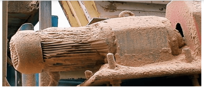
Overheating of dust layers on electrical equipment (e.g. motors) leading to a re is usually a slow process. Dust layers should be removed regularly to control this problem and in any case, should not exceed 5 mm thickness.
Lightning
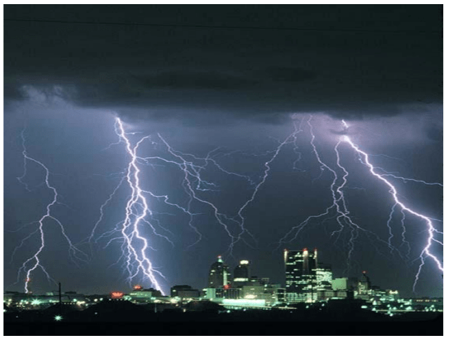
If lightning strikes a flammable atmosphere, ignition will always occur. Moreover, there is also a possibility of ignition due to the high temperature reached by lightning conductors.
Large currents ow from where the lightning strikes and these currents can produce sparks in the vicinity of the point of impact.
Even in the absence of lightning strikes, thunderstorms can cause high induced voltages in equipment, protective systems and components. In practice, the probability of a lightning strike depends on the specific location of the site and a specialist should be consulted to ascertain whether additional precautionary measures are required.
As a general precaution against external sources of ignition, all vents handling flammable gases and vapours should be fitted with a suitable flame-trap!
Static Ignition & Thermal Instability
The next article in this series of eight is entitled: Static Ignition & Thermal Instability.
The aim of these articles is to help you establish a simple basis of safety in your plant and dispel some of the myths associated with process and safety risk assessments.
LEADERS IN ATEX INNOVATION TO THE HAZARDOUS AREA INDUSTRIES
Thorne & Derrick are leaders in the development and distribution of Product Innovations that deliver significant improvements to clients plant, people and operational safety in the explosive atmosphere industries.
Your proactive problem solvers experienced in succession planning for the replacement of obsolete, non-conformant and legacy equipment in hazardous areas.
Your first-choice provider of innovative and competitive solutions to ensure ATEX & IECEx Compliance for Hazardous Area Electrical, HVAC & Process Instrumentation Equipment to UK and international projects.
Press Release Date: 02.04.2020 uploaded by Chris Dodds (T&D Sales + Marketing Manager) World’s First Fully Certified ATEX Doors Thorne & Derrick International, the Experts in Equipment for Explosive Atmospheres, today announce the signing of a Commercial Distribution Agreement...
Press Release Date: 04.07.2019 uploaded by Chris Dodds (T&D Sales + Marketing Manager) Category: Stockist Distributor Agreement Announcement Thorne & Derrick International announce that they have signed a Preferred Distributor Agreement with Raytec, the world leading manufacturer of LED...















 appropriate explosion protection solutions to industry with full back up services. With 42 years of experience providing Explosion Hazard Services to the process industry, ATEX Explosion Hazards Ltd have a wide range of expertise within their group of companies.


 Reliable function thanks to redundant design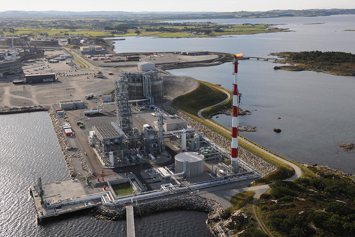





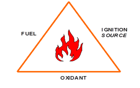 control (i.e. eliminate) one of the THREE basic components for combustion?
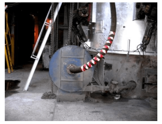


 All metal items and fittings (e.g. funnels, metal spirals in flexible LEV trunking, etc.) should be in good contact with each other and with earth. For example, Blo-line / Morris couplings have an integral earthing strip (as shown in the photo above) to ensure electrical continuity through the coupling and along the pipework.