They promote good practices for protecting personnel and plant via a range of platforms including Exhibitions, Conferences, Workshops, Seminars and Webinars that take place across the globe.
Hazardex gives industry leaders the chance meet up (virtually via the Hazardex forum on LinkedIn) or at their events to discuss and engage to ensure workplace and worker safety in potentially explosive atmospheres.
Hazardex is the recommended resource for any queries or developments surrounding the following standards: the European ATEX Directives, IECEx, Hazloc, CENELEC, CSA, IECEE, IECQ, SILs and functional safety IEC 61508 & IEC 61511.
PPTex: Launched in July 2018, PPTex (Personnel Protection Technologies) is a complimentary, quarterly supplement to Hazardex with its own additional circulation to SHE/HSE specialists involved in selection / equipment for worker safety. The supplement focuses on technologies that incorporate electronic and technological systems that the user can wear, hold or use to improve personal safety. For more information about the Media Pack or to subscribe via the application form.
Hazardex 2021 Conference & Exhibition
2021 Hazardex International Conference and Exhibition will be taking place once again at the Majestic Hotel in Harrogate, North Yorkshire, UK on February 24th and 25th 2021.
The two-day Conference & Exhibition, which also includes workshops, a networking dinner and awards ceremony, aims to strengthen and expand the community that looks to the Hazardex website and journal for industry intelligence and information.
Sponsorship, exhibitor or visitor queries should be addressed to the Event Director Russell Goater phone +44 (0) 1732 359990.
The Hazardex 2021 Conference will have a focus on several topics including:
Personal Protection Technologies (PPT) and Smart Wearables
Automation & IIoT
Risk Assessment and Management
Functional Safety
Cybersecurity
Decommissioning
Engineering & Design Safety
Human Factors
Safety Culture
Environmental Protection
An Introduction to ATEX/DSEAR
Knowledge & Competence
Asset Management and Maintenance
Regulation
Process Safety Leadership
Fire & Explosion Hazards
This list is not exclusive. Anyone with an original take on any aspect of hazardous area operations or process safety is encouraged to get in touch.
There is no charge to submit or present, although we are seeking only non-commercial papers which aim to share expertise and knowledge.
All speakers will get an inclusive pass for all conference sessions plus a seat at the prestigious Awards Gala Dinner on the evening of February 24.
Why HazardEx?
“Thorne & Derrick have worked closely with Hazardex over the years attending the yearly Conference and sharing content to improve digital contact within the hazardous area sector, which was outside our normal reach.
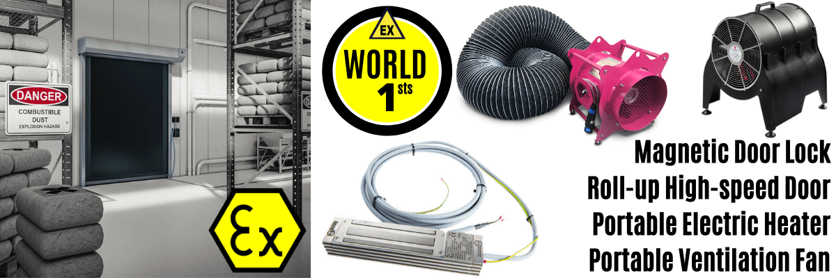
Our ATEX Doors feature in this months digital and print magazine has enabled us to reach the inboxes and desktops of decision makers who can now influence the specification, recommendation and direct purchase of several new product innovation launches for the hazardous area sector.
Hazardex are customer responsive to requests and strategically driven to achieve our marketing goals and objectives. We are now reaching a larger audience with a stronger market position and benefiting from new business lead flow. I wouldn’t hesitate to recommend HazardEx and their sales and marketing tools to other businesses.” Chris Dodds Sales & Marketing Manager at T&D.
Distributed in the UK by Thorne & Derrick, the Dynaco S5 range of ATEX certified door systems provide improved traffic flows with significant energy savings and reduced carbon footprint. Contact us for further information.
Follow our Showcase Page on LinkedIn to receive hazardous area product innovations, industry news, whitepapers, videos, technical tips and training webinars for professionals involved in the explosive atmosphere industries.
With over 35 years experience of designing and supplying trace heating cables & systems Thorne & Derrick have earned the title of ‘The Trace Heating Specialists’– we hold the largest UK stocks of leading heat tracing cable brands.
Experts in trace heating solutions, including ATEX trace heating for use inindustrial & explosive atmospheres, Thorne & Derrick have the knowledge & expertise to help clients prevent unnecessary down time this winter. We also hold large UK stocks of frost protection and winterisation equipment helping to keep your plant and personnel operational even when temperatures begin to plummet.
The following blog will aim to answer the following questions:
What is Trace Heating?
How do Trace Heating Cables work?
Best way to install a Heat Trace System?
How to test your Trace Heating is working?
Do I need a Thermostat with my Trace Heating?
What are the different types of Trace Heating Cables?
Typical Trace Heating Applications
If you can’t find the answer to your question please don’t hesitate to contact usand one of our friendly team will be more than happy to help.
What is Trace Heating?
Trace heating is a vital process used to heat up or maintain the temperature of pipes and vessels by using specially engineered cables. During winter months it can become extremely cold and temperatures often dip below freezing.
The most widely needed benefit of the system is the prevention of freezing within pipes. With temperatures dropping daily during the winter months freezing pipes are a major concern for homeowners, businesses and industry alike. By maintaining the ambient temperature inside the pipe, frost cannot build up and pipes will not freeze. This will stop pipes from due to ice expansion.
T&D’s Top Tip – Heat rises, always install heat tracing cable directly to the underside of the pipework for optimum heat dissipation.
➡ Thorne & Derrick’s heating cables and systems can be used for commercial, industrial and hazardous are heating of pipework, tanks, drums and vessels in both safe, non-hazardous and hazardous area locations.
How do Trace Heating Cables work?
Trace heating cables are a simple solution to a common problem – stopping pipes from freezing. An electrical element or trace heating cable is fitted along the length of a pipe – this uses electricity and insulation to maintain or increase the temperature of pipes or other vessels, replacing any heat lost to outside temperatures.
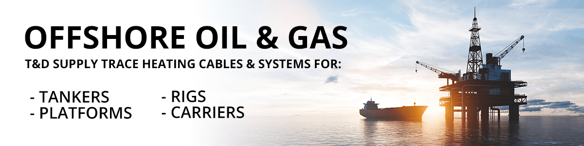
Offshore Oil Gas Trace Heating
Best way to install a Heat trace system?
To successfully install a heat trace system please refer to the manufacturer’s installation instructions. The following are some basic tips and instructions but please always refer to the manufacturer for detailed guidance.
Firstly identify the correct trace heating system by calculating heat loss, maximum operating and ambient temperatures, class and length. Next ensure the pipes are in fully working order – including a pressure test.
Identify the route of the cable by walking the length of the piping and make sure all surfaces where the cables will attach to are free of dirt, rust and any other obstructing objects. if necessary remove any old tape and any other combustible material.
Determining the maximum cable circuit length for your system is very important. If you need any help please contact our friendly team who would be happy to help. Wire cutters will help to cut the cable to the desired length.
Combine the cables with termination and splice kits, tee kits, end seals, and other accessories to complete the trace heating system.
How to test your Trace Heating is working?
Testing all cables on a regular basis is key to maintaining systems and ensuring that they are work properly. Following the below steps as well as manufacturer’s instructions will help to test and troubleshoot effectively.
Walk down the lines on site to ensure all is present and correct
Make sure that the system is running at the proper voltage
Ensure that properly rated breakers are working correctly
Check the resistance and wiring of the circuit from the load side of the breaker
Megger test your entire system
Megger the trace heating at the power connection
Do I need a thermostat with my Trace Heating System?
Thermostat control is recommended for use with all trace heating systems. Temperature control can reduce system operating costs by as much as 90%.
For simple frost protection applications Thorne & Derrick would recommend the Heatfast HF9101-V1. This model is factory set to switch at 5°C meaning it is tamperproof. It offers mains failure and sensor failure alarms and has VFC relays to communicate with any BMS. The thermostat can switch 25A and can directly accommodate up to three heat tracing cables and a mains power cable.
What are the different types of Cables?
Parallel Heat Tracing Cables
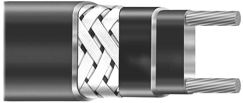
Parallel heating cables are typically available in two distinct variants; constant wattage and self regulating (also known as self limiting).
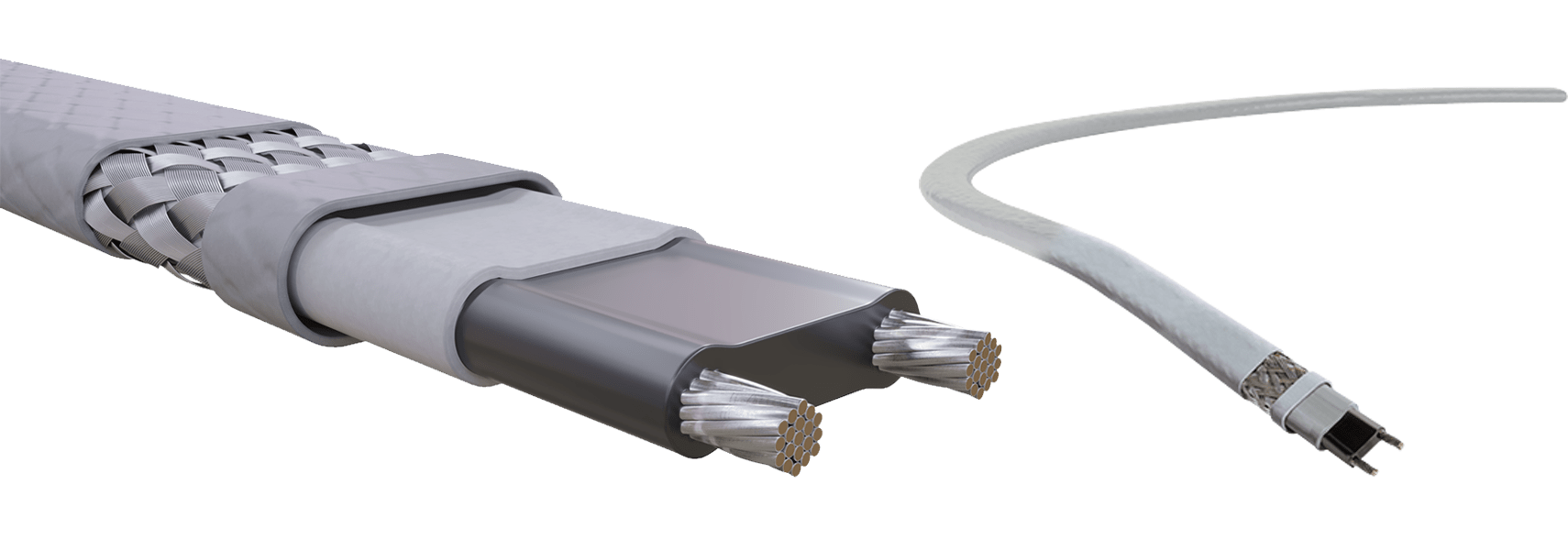
Parallel heat tracing cables use two ‘normal’ copper conductor wires. These run in parallel along the length of the wire and form the basis of live and neutral. The heat load is then created by two different methods. In the case of constant wattage cables, a fixed resistance filament is then spiralled along the length of the cable. Then it is soldered alternately to the live and neutral wire in fixed distances creating what are referred to as heating zones.
Essentially, every zone is a fixed resistance circuit supplied by a fixed voltage, providing a constant wattage along its length. Since each zone of heating is essentially in parallel with the zone before it, the supply voltage will remain constant along the length of the heating cable. Other than from a small voltage drop brought about by the summation of the tiny resistances of the live and neutral wires as the cable gets longer and longer.
Thermon FP Heat Tracing Cable
Self Regulating Heat Tracing Cables
Self regulating or self limiting cables also provide a controlled wattage per metre of cable but with a difference in terms of construction and performance.
The live and neutral wires are co-extruded into a polymer based material containing particles of carbon, providing a resistance path and hence circuit along the length of the heating cable.
However, this resistance and therefore the output of the self regulating heating cable varies depending upon the temperature, due to microscopic expansion and contraction of the polymer.
This type of cable reduces its power output as temperature increases and conversely at lower temperatures, the power is increased.
Self regulating heat tracing cables have an improved level of inherent efficiency as well as increased safety, if its application is correctly considered. Starting with the former, at higher temperatures the heating cable backs off its output, saving power even if not connected via a controller or thermostat.
This is not to say it will hold a fixed target temperature without external control, but the reduction of output as the work-piece temperature increases is a desirable feature from an energy conservation perspective.
This also gives rise to another highly desirable characteristic of self regulating cables, which is the ability to assign a T class (temperature rating) for ATEX purposes and safe installation in hazardous area locations. With the decrease in power output as the cable temperature increases, it is not possible for the cable to affect an increase to a temperature beyond a certain level, regardless of the level of thermal insulation used.
Prevent pipes and vessels freezing by installing self regulating frost protection trace heating cables. Snow build-up causes serious structural problems to roofs and buildings. This occurs due to problems from the added weight and then the flood damage issues that arise as the snow begins to thaw.
Hot Water Temperature Maintenance
Preventing Legionnaires’ disease is possible in hot water systems by installing trace heating to maintain 60°C. This is in line with the ACOP L8 (4th edition) requirements. Significant space and cost savings occur by alleviating the need for a HWS return leg. Thorne & Derrick have experience in design and installations for a number of different applications including football stadiums, schools and hospitals.
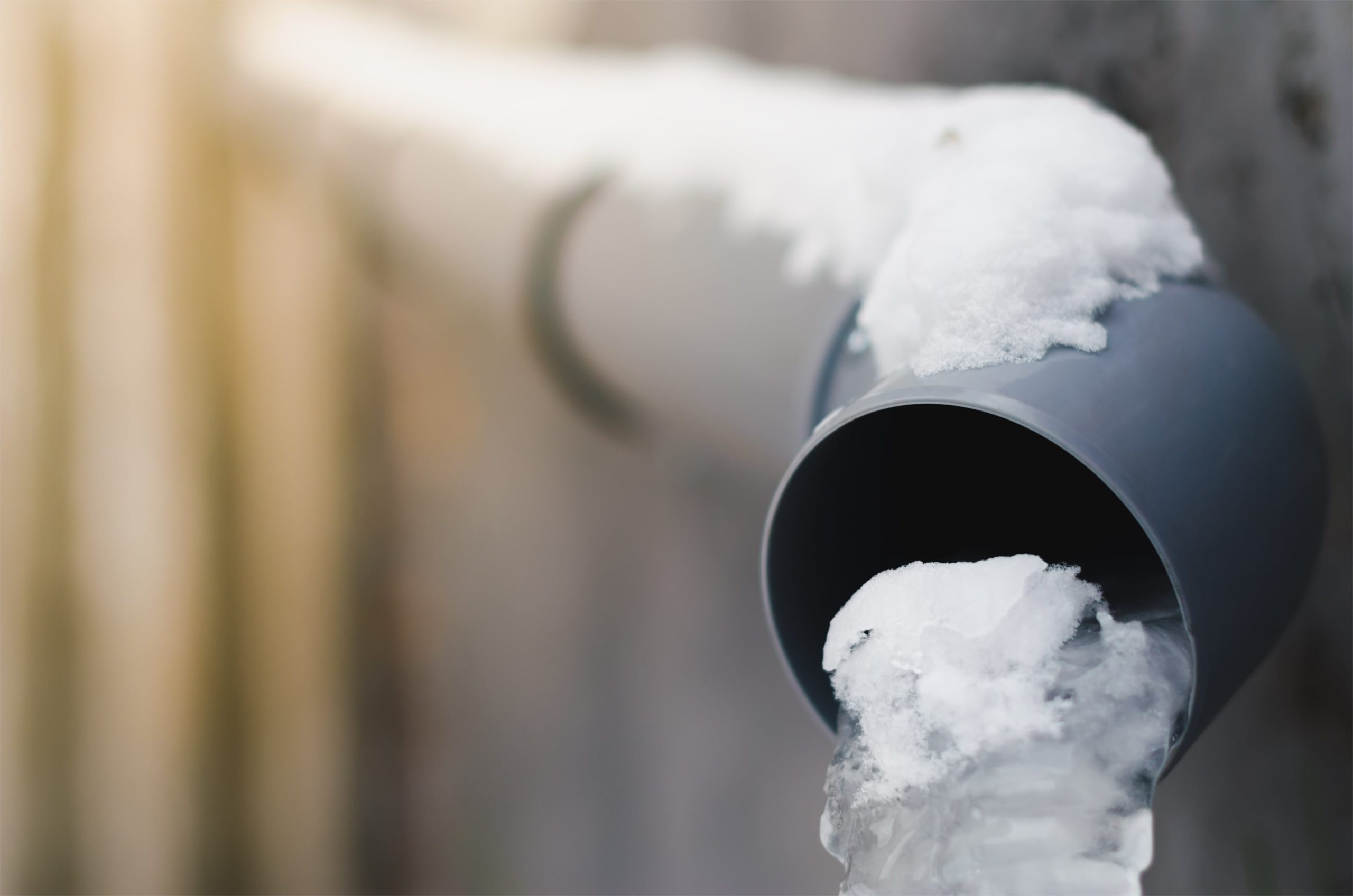
Frozen Rain Water Requires Gutter Heating System
Ramp Heating Solutions
Trace heating cables can be used to prevent snow & ice build up on ramps, paths and access routes. This helps to eliminate accidents caused by freezing conditions. We can provide solutions for direct burial in either concrete or asphalt. With our extensive design and installation experience we are confident providing solutions for both new and retrofit systems.
Roof and Gutter Heating Systems
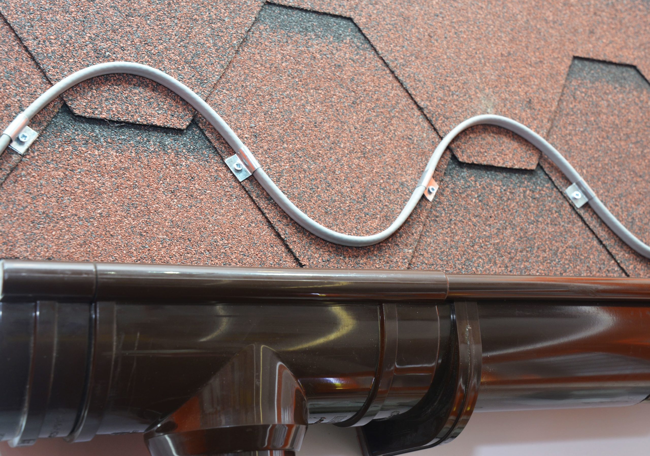
Roof and Gutter heating systems can prevent ice and snow build up/damage to roof, roofgutters and downpipes. Stops water ingress/damage, burst down pipes, gutter cracking or deformation, and dangerous snow or ice falls from the roof. Site surveys available on request.
Roofing heating cable for ice and snow melting. A close-up on a roofing deicing system, ice-melting cable installed above the rain gutter on an asphalt shingled roof
Fire Escape Heating
Trace heating cables stop the accumulation of snow and ice on external escape routes. This removes the risk of slip hazards. It is a cost effective solution to satisfy current building regulations without the requirement to fully enclose the escape route.
We recommend the use of self regulating trace heating cables attached to the underside of the stair tread. Robust, durable heating cables designed for this application provide enough heat output without having to install thermal insulation.
➡ T&D distribute the most extensive range of Hazardous Area Electrical Heating enabling flow, workplace heating and and process heating in all industries.
Since 1985, Thorne & Derrick the UK’s largest stockist and supplier of heat trace cables and systems providing engineered Trace Heating Solutions to prestigious project. Please contact us with your enquiry.
Trace Heating Services Provided
Most Competitive Prices & Fast Delivery to UK & International Locations
Expert Technical Support from Trained Staff
Project Specification & System Design Services
UK Approved Installer Networks
Commercial, Industrial & Hazardous Area Marketplace Competency
EXPERTS IN WINTERISATION SOLUTIONS FOR INDUSTRIAL & HAZARDOUS AREA ENVIRONMENTS
Thorne & Derrick hold the largest UK stocks of frost protection & winterisation equipment to help keep your plant and personnel operational during the winter months.
Thorne & Derrick understand that prolonged periods of low ambient temperatures can bring operations to a standstill costing thousands of pounds in lost downtime.
Experts in heating solutions for use in industrial & explosive atmospheres, Thorne & Derrick have the knowledge & expertise to help clients prevent unnecessary down time this winter.
We can provide overnight delivery of Trace Heating Cables at the most competitive prices to guarantee frost protection of your pipelines and mechanical services.| Ask About Our Heat Trace Design Service.
💡 Contact us today and our skilled and friendly team can provide technical support. As well as this they can offer reliable, fit for purpose and compliant solutions to suit your exact requirements.
Explosive Atmosphere & Hazardous Area Lighting Solutions
Thorne & Derrick International, based in the UK, are Preferred Distributors and Stockists for the Raytec SPARTAN range of ATEX lighting using LED technology for the illumination of hazardous area locations and potentially explosive atmospheres.
SPARTAN Linear, manufactured in the North East of England by Raytec, offers the ideal LED lighting solution for new installations, or as a retrofit for existing fluorescent luminaires.
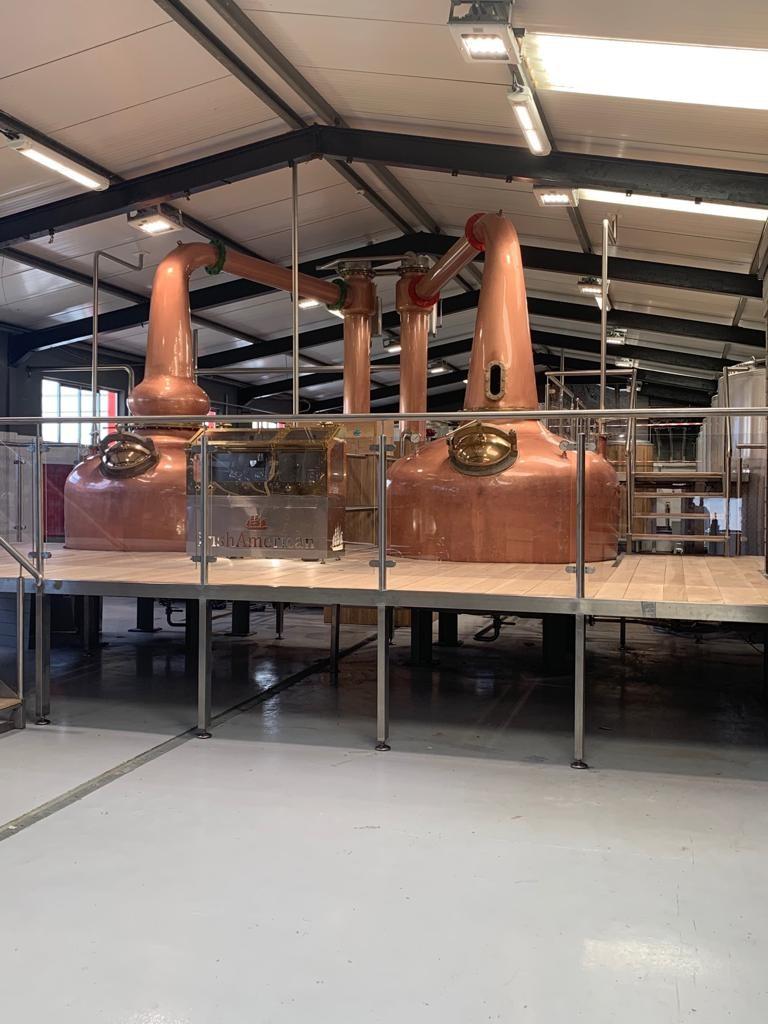
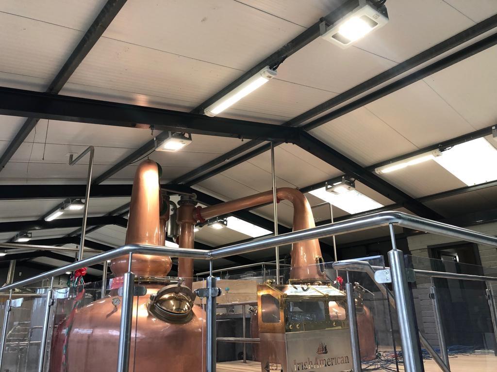
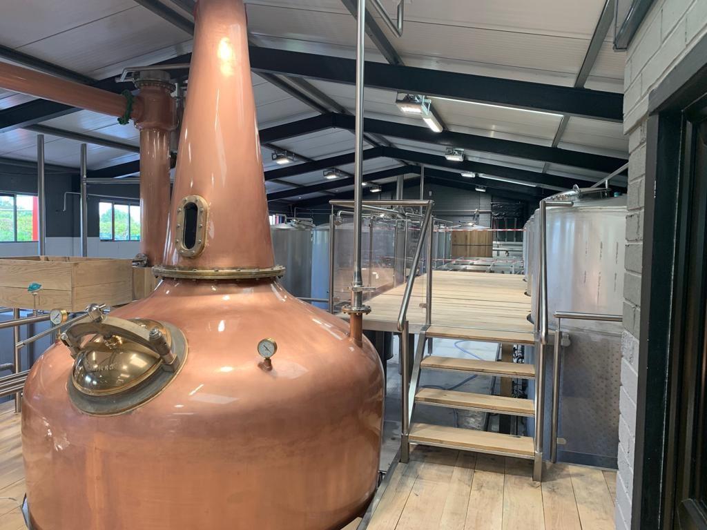
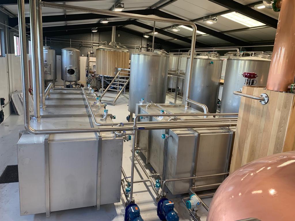
Recently, Raytec supplied the Irish American Whiskey Distillery with our SPARTAN Linear and High-Power Flood luminaires, which now provide the distillery with quality illumination throughout the site.
With the distillery being part of the Irish Whiskey tour, all fittings were painted white and supplied with 4,000K LEDs to fit in with the aesthetics of the building. A number of emergency variants were also installed to provide back-up illumination.
Industry leading manufacturers of Lighting Products for hazardous areas | Raytec
SPARTANis a full range of Ex LED luminaires and lighting approved for all ATEX and IEC Ex Zone 1 and Zone 2 hazardous area environments, including UL /CSA C1D2 installations. The hazardous area lighting products are designed for the most extreme environments – Flood, Linear, Bulkhead, Bay and Crane luminaires with emergency and industrial lighting versions are also available from Thorne & Derrick International.
Hazardous Area Lighting Design
Thorne & Derrick’s hazardous area lighting design service is completely free of charge, providing you with a visual 3D representation of the final lighting solution, with detailed lux levels and a true indication of lighting performance. Our lighting design experts will guide you through the entire process, ensuring the optimum lighting solution is achieved.
leaders in ATEX Innovation To The Hazardous Area Industries
Thorne & Derrick are leaders in the development and distribution of Product Innovations that deliver significant improvements to clients plant, people and operational safety in the explosive atmosphere industries.
Your proactive problem solvers experienced in succession planning for the replacement of obsolete, non-conformant and legacy equipment in hazardous areas.
Your first-choice provider of innovative and competitive solutions to ensure ATEX & IECEx Compliance for Hazardous Area Electrical, HVAC & Process Instrumentation Equipmentto UK and international projects.
Follow our Showcase Page on LinkedIn to receive hazardous area product innovations, industry news, whitepapers, videos, technical tips and training webinars for professionals involved in the explosive atmosphere industries.
The ATEX Fan Guide | EN14986 Explosive Atmospheres & Hazardous Areas
ATEX Fans – EN14986
Republished with kind permission of Hazardex
Introduction
ATEX fans are fans designed for use in potentially explosive atmospheres and are governed by EU Directive 2014/34/EU. This Directive is intended to increase safety by using a logical risk identification and mitigation method for design manufacture and use.
With so many fans in operation in potentially hazardous areas, and the real and perceived risk of such fans causing a possible ignition, in addition to the general mechanical standards (ISO/IEC 80079-36 & 80079-37), a specific EN (Euro Norm) standard exists.
EN14986:2017 Design of fans working in potentially explosive atmospheres details design and documentation requirements for ATEX fans.
As fans are essentially mechanical devices there is no legal requirement for third party certification, issuing of ATEX certification is left to the person or body placing such equipment on the market.
However for an end user, having such a certificate is not the full picture, there is still a degree of due diligence required to ensure the equipment is suitable.
Whilst an end user could not reasonably be expected to carry out a clause by clause verification for a given fan, there are a few fundamentals that should be checked.
This document aims to give a guide to engineers on the main features of such fans and to help in verifying there suitability for a given application.
Hazardous Area Zones and Categories of Equipment
Historically electrical equipment was designed for operation in “zones”.
The zoning of an area within an industrial facility is usually a result of a HAZOP study at the early stage of development. The important thing is that this is an “end user” responsibility, it is not the responsibility of a machinery supplier to specify the applicable zone for a hazardous area.
The recognised zones are;
Gas
Dust
Definition
Zone 0
Zone 20
Hazard present in normal operation of for long periods (typically >1000 hr/year)
Zone 1
Zone 21
Hazard is likely to occur in normal operation (typically >10 but <1000 hr/year)
Zone 2
Zone 22
Hazard not likely to occur in normal operation and, if it occurs, will only exist for a short time. (typically <10 hr/year)
Having established the relevant zone for a given area, the ATEX directives then categorise equipment by its suitability for use in a given zone.
The category of equipment can be considered a “degree of protection”. Three categories of equipment are available, category 1 given the highest degree of protection and category 3 the lowest. Categories are further denoted by either G (Gas) or D (Dust) depending on the nature of the hazard.
Zone 0
Zone 1
Zone 2
Gas
Dust
Gas
Dust
Gas
Dust
1G
1D
2G
2D
3G
3D
Again as with zoning the selection of category of equipment is the responsibility of the end user, though generally this is taken direct from the table above.
However in some circumstances a higher category of equipment may be chosen, ie category 2G equipment in a Zone 2 Gas hazard. An example maybe where the consequence of ignition is deemed so severe, regardless of the possibility, that equipment with a higher degree of protection is selected.
It follows that any fan supplied needs the correct level of protection, or in other words is manufactured to the correct category. This should be clearly shown on both the label (see below for explanation of labelling) and any documentation.
If the category of equipment is not clear on both documentation and labelling then it may not be the correct fan.
Industrial fans can be roughly split into two sectors
1) Standard designs – for ATEX units these will carry the manufactures certification, including ATEX Category. In this case the user can ensure it is suitable for their application
2) Configured or bespoke design – for ATEX units these will be deigned to meet the category specified. Here the user needs to tell the manufacturer the required category.
Maximum Surface Temperature
An important part of the concept for ATEX fans is control of temperature, in both normal and possible upset/fault conditions.
By keeping temperatures below a critical value ignition can be controlled. Different gasses and dusts have different critical temperatures. These are often called the “auto ignition temperature” meaning the temperature where, even without an additional ignition source the gas/dust will ignite.
The end user is responsible for products used/produced in their facility and it follows therefore, as with zones and categories, that specifying the maximum allowable temperature is their responsibility.
Gasses are generally grouped in one of 6 temperature groups T1 to T6.
Gas Temp Class
Max allowable surface temp
Gas Temp Class
Max allowable surface temp
T1
450ºC
T4
135ºC
T2
300ºC
T5
100ºC
T3
200ºC
T6
85ºC
For dusts the actual maximum surface temperature is given eg 135ºC
For dual certified equipment, that that is suitable for both a gas and dust hazard both the gas and dust temperature must be given eg T4 T135ºC
Similar to with the categories if a standard pre certified fan is being selected then the suppliers documentation should shows the maximum surface temperature to enable the user to ensure correct selection. For a bespoke unit temperature needs to be given to enable design to be carried out.
Equipment Protection Level (EPL)
This is a relatively new concept and is based on the Zoning of equipment and the ignition hazard assessment. Here possible faults/sources of ignition in the fan are assessed.
Zone
ATEX Equip
Ignition source present during
EPL Gas/Dust
Normal Operation
Expected Malfunction
Rare Malfunction
0
1
yes**
yes**
yes
Ga/Da*
1
2
no
yes
yes
Gb/Db*
2
3
no
no
yes
Gc/Dc
Notes * EN 14986 does not cover manufacture of Zone 0 cat1 Da fans.
** For Zone 0 cat 1 Ga fans two measures required to prevent ignition source second of which is an “explosion proof” case and flame arrestors.
Flame arrestors cannot be used for Da protection as these would blind up due to conveyed dust hence exclusion of Da EPL.
What does this table tell us?
For fans used in Zone 0 where hazardous gas is normally or frequently present INSIDE the fan case highest level of protection “a” required. Fan is designed so there are two separate mitigations to prevent ignition in normal operation and during an expected malfunction. Fan is also safe in event of a rare malfunction which could be two simultaneous expected malfunctions. Such zone 0 fans are very specialised and are subject to third party testing and certification.
For Fans used in Zone 1 a medium level of protection “b” is used to give protection in normal operation and during “expected malfunction”
For Fans used in Zone 2 the lowest level of protection, “c” is used giving protection during normal operation.
Fans present a couple of anomalies.
The use of “material pairings” (see Detailed fan design – material pairings below) is still required for Zone 2 fans in many cases
The possible different zones, categories and protection levels inside and outside the fan casing. This often requires dual labelling. Generally to take into account that few fans are truly “gas tight” only one category difference is allowed between the internal and external of a ducted fan.
Protection Concept
This is a relatively new concept but is a guide to how the EPL has been achieved. Readers may be familiar with the Exd marking of electrical equipment where the d indicates explosion protection – any explosion is prevented from propagating beyond the motor housing.
For mechanical equipment the available options are;
Protection Concept
Flameproof
Pressurised
Enclosure
Construction
Control of ignition
Liquid immersion
Code
Exd
Exp
Ext
Exh
Exh
Exh
En 14986 covers “constructional safety” so fans complying to it should be marked Exh.
Labelling
Correct labelling is important. It gives a quick easy way to check the suitability of a given fan. Clearly displayed on the nameplate should be something in the format shown below.
Key
CE mark
Ex mark showing equipment is ATEX certified suitable for potentially explosive atmosphere
II Roman numeral 2 denotes equipment group I is for mining equipment II surface equipment. EN 14986 covers only group II equipment.
2GD 3G2D Equipment category 1,2 or 3. G for Gas, D for Dust & GD combined gas & dust
Exh Protection concept. Applies to internal and external zoning of fan
IIB This specifies the gas group. Gas groups are IIA typically propane, IIB ethylene and IIC hydrogen.
IIIB This specifies the dust group. Dust groups are IIIA combustible flyings, IIIB non-conductive dust, IIIC conductive dust.
Gb Gc & Db Equipment protection level for gas and dust both inside and outside fan case
T175ºC max surface temp dust. Common values 110, 135 145ºC / separation between internal and external of enclosed fan case. It should be clear if the fan is certified the same internally and externally or if these are different.
If you can’t see this information on your fan nameplate you may not have the correct certified fan, or even not an ATEX fan at all.
Unlike electrical equipment there is no notified body number as equipment is self-certified. As mentioned in the introduction this is acceptable for mechanical equipment but there is a degree of due diligence required from the user that correct equipment has been selected.
If your fan is marked Exd be careful that somebody has not just transferred the motor marking to the fan case, it happens. Fans complying with EN14986, where this standard is taken as the overarching design document cannot be marked E xd!
Detailed Fan Design
EN 14986 sets out a number of minimum design rules to which hazardous area fans should comply. It is legally possible to produce a fan that does not comply and complies with ISO/IEC 80079-36 & 80079-37 but there would have to be a very good reason why – such special cases where they do exist are beyond the scope of this paper.
The following section looks at some of the more important design requirements of EN14986.
Maximum Surface Temperature
From the section on marking it can be seen that the maximum expected surface temperature inside / outside the fan case should be displayed. This is the highest of either:
1) Maximum temperature in operation due to heating eg bearings, seal friction etc
2) Max temperature at fan outlet. This is as a result of the “work done” on the gas as it passes through the fan. The standard applies a 20% margin on the calculated/measured outlet gas temperature in degrees C
Note it is NOT possible to ATEX certify a fan for are given temperature, for example T4 when the maximum design temperature of the gas already exceeds this. This may seem obvious but the author has seen countless examples of this especially on ID fans in the oil/gas & petrochemical industries.
Material Pairings
Although the protection concept is ‘exh’ i.e. by design the standard identifies that in the event of expected malfunction or rare malfunction there is a high possibility of contact between stationary and rotating parts. This would be the impeller inlet and inlet cone on a centrifugal fan and blade tips and casing on an axial fan.
The material parings have been selected to reduce risk of sparks and hot spots due to frictional rubbing in the event of movement between stationary and rotating parts. In general the common pairings are given in table below
A full list of all pairings with notes is given in EN 14986 clause 4.7.2 table 1
Material 1
Material 2
Category 3
Category 1 & 2
Notes
Carbon & Stainless Steel
Aluminium alloy
Navel Brass
CuZn39Sn
yes
yes
Most common method used
3
Aluminium alloy
Aluminium alloy
Navel Brass
yes
yes
1
Steel alloy
Stainless steel
Nickel alloy
Steel alloy
Stainless steel
Nickel alloy
yes
yes
2,3
Steel alloy
Brass CuZn37
yes
no
2
Brass should be the stationary part
Plastic
Plastic
Aluminium
Steel alloy
Stainless Steel
yes
yes
4
Rubber coated material
Rubber coated material
Steel alloy
yes
yes
5,3
Notes
Aluminium should contain approx. 12% silicone. This gives a brittle structure which will fracture rather than deform under prolonged contact
These pairings will cause sparks and therefore are restricted to; motor power 5.5 kW, relative rubbing speed 40 m/sec AND where the specified clearance between parts can be assured on installation and during use. Manufactures instructions should include details on how to measure and maintain clearance in use.
Outside of these parameters, for example where fan is handling corrosive chemicals, other forms of protection are necessary.
Stainless steel should be Austenitic non magnetic
The use of plastic should be carefully considered due to, low thermal conductivity leading to hot spots, low mechanical strength and possibility of static discharge. For category 1 & 2 fans plastic should withstand short term exposure to flames. Details should be given in technical documentation
For rubber lined impeller maximum tip speed 70 m/sec (223mm dia impeller at 3000 rpm, 446mm dia at 1500 rpm). Minimum clearances to be maintained in use.
What can we conclude from the above?
a) For most common method of protection correct brass must be used. If “Navel Brass” is NOT used then restricted to category 3 (zone 2 machines) and <5.5 kW & 40 m/sec rubbing speed see c below
b) Historically aluminium has been used as a non-sparking material, however if aluminium on aluminium is used the requirement for minimum silicone content may result in material being unsuitable for impeller
c) If steel on steel or stainless on stainless is used this is limited to small fans (127mm contact diameter at 3000 rpm or 254mm at 1500 rpm). Also user must be able to confirm clearance when fitted – often this is unrealistic. IOM manual should contain instructions on required gap and how to measure it. User should measure this gap record it and check it as part of maintenance procedures.
d) Plastics need careful selection and IOM should contain details of plastic used with regard to thermal, electrostatic and flame retardant properties.
Clearances between rotating elements and fan casing
En 14986 states “the clearances between rotating elements and fan casing is the most important safety feature of ignition minimising fans.
As such it is important that this is not only correctly set by the manufacturer but also maintained in operation. As we have seen above regarding material pairings there is a requirement for certain pairings that this is ensured on site. The manufactures instructions should give details how this can be maintained on site.
A fan supplied without this information is not an ATEX fan! Similarly if a fan is installed with for example a steel on steel material pairing and no records of the actual running clearance when installed exists then there is no certification.
Bearing in mind the size restriction for such a pairing and the practical difficulties of measuring the clearance it is difficult to justify such a selection in the vast majority of applications.
If you have an ATEX fan with no information on the running clearances or how to check them you should ask why not?
Fan Casing
These should be rigid design, generally with fully welded seams and designed to minimise leakage. If fan is not gas tight or leakage rates are not known only one category difference between internal & external is allowed to take into consideration leakage.
Impeller Construction
Impellers should be of rigid design, and either
a) Tested at 115% running speed
b) Designed such that primary stresses (tangential, radial and bending) are 2/3 material yield stress
A welded construction, cast or moulded with appropriate thicknesses is deemed to satisfy the rigid design criteria without additional testing regarding rigidity. Conversely a lightweight design of say folded tabs or rivets would require some testing to ensure rigidity.
Note rigidity and strength are easily confused, an impeller could be rigid (its resistance to deformation under an applied load) but fail due to strength (stress due to centrifugal loads under rotation), conversely a riveted impeller may pass the 2/3 stress criteria but deform under operation so as to reduce significantly the running clearances.
Whilst it is not reasonable for an end user to check a suppliers calculations there should be in the fan documentation some indication that either an over speed test has been carried out or reference to impeller stress calculations.
Testing
EN 14986 does not specify a particular test procedure, but it does state that vibration levels should be to ISO 14696:2003.
The easiest practical way to do this is to run test the fan. Fan documentation should refer to run test and show residual vibration levels. In the case of large units where a factory run test is not practical this may be done for instance on site with prior agreement.
There should be some reference to a run test and vibration readings in the fan documentation, if not has this been done?
Technical File
Each ATEX fan should have a technical file. This is a comprehensive document identifying the fan, and showing compliance with the detailed requirements of EN 14986. The technical file is not necessarily provided to the end user.
For Category 3 machines the manufacturer or importer (the organisation that places the fan “on the market”) should keep the technical file for a minimum of 10 years after the product was last manufactured. For Category 2 & 1 equipment the technical file should be lodged with a notified body.
Note this does not mean the notified body has any role in checking the technical file, it is simply an independent “safe” storage of the technical file should it be required to be inspected (possibly as a result of an explosion).
The quoting of a notified bodies’ reference for technical file storage on an ATEX certificate does not imply any form of approval/inspection/certification from that notified body. This is a common misconception giving purchasers and users the false impression of third-party verification.
Documentation
Reverence has been made in proceeding sections to the documentation provided with the fan. This is substantially more than just an ATEX certificate, though this is important.
The document package should include
a) Shipping and Storage instructions
b) Erection and Commissioning manual typically including
I) General installation notes
II) Checks prior to installation
III) Erection procedure
IV) Pre commissioning & commissioning checks
V) Bolt tightening torques
VI) Sub suppliers instructions (eg electric motor)
VII) Minimum and maximum airflow rates required to maintain maximum surface temperature
VIII) Specific information regarding maintaining clearance between rotating and stationary parts
The manual should include relevant forms to focus the installer towards key items. These should form the basis of a check sheet to record such things as clearance vibration levels and ideally be returned to manufacturer
c) Operating and maintenance manual
I) Performance data
II) Detailed description
III) Health and safety
IV) Operation of the fan
V) Maintenance
VI) Fault finding and rectification
VII) Sub supplier’s information
VIII) Fan application category (BV1-BV5) according to ISO 14694
IX) Specific information regarding maintaining clearance between rotating and stationary parts
d) Particle limitations with regard to ingress of foreign particles
e) Routine inspection and servicing.
This should make it clear that the ignition minimising properties of the fan and its accessories can only be retained if routine inspections and maintenance is carried out. It should address the following.
I) Inspection intervals taking into account operating conditions
II) Recommended spares
III) Wear of consumable components eg belts bearing seals flexible joints
IV) Inspection of rotating components
V) Seals and gaskets for fans having different categories internally and externally
VI) Any monitoring devices are regularly checked
VII) Additional cleaning requirements for category 2D & 3D internally fans where dust build up mare cause additional hazards
Clearly there are significant document requirements for all ATEX fans. If the fan documentation does not follow the above this should prompt further investigation.
Conclusion
We can conclude that in order to correctly install an ATEX fan there has to be a considerable interchange of information between User and Supplier.
If an ATEX fan is to be installed in either a new plant or exisiting then there has to be interchanges of at least the following information:
Zone and category of fns both internally and externally
Gas/Dust group and maximum allowable surface temperature
Normal and expected operating conditions
Correct marking that captures the above items
Information pertenant to maintaining the explosion protection features of the fan
Certification showing compliance with relevant design code. (EN14986 in most cases)
Comprehensive documentation with regard to operating installation and maintenance
Whilst it is possible to buy fans that seem to have blanket certification making the purchasing easy the question has to be asked if the above flow of information is absent is it really an ATEX fan?
Thorne & Derrick stock and distribute trace heating cables and provide heat trace system designs for process maintenance, pipe and vessel freeze protection – this includes industrial and hazardous area approved electrical trace heating for potentially explosive atmospheres (ATEX & IECEx).
Ammonium Thiosulphate is an inorganic compound that is white crystalline solid with ammonia odor, readily soluble in water, slightly soluble in acetone and insoluble in ethanol and diethyl ether.
Formula:H8N2O3S2
Molar Mass:148.20 g·mol−1
Freezing Point: 0°C
Trace heating is able to heat up and maintain Ammonium Thiosulphate in highly corrosive atmospheres.
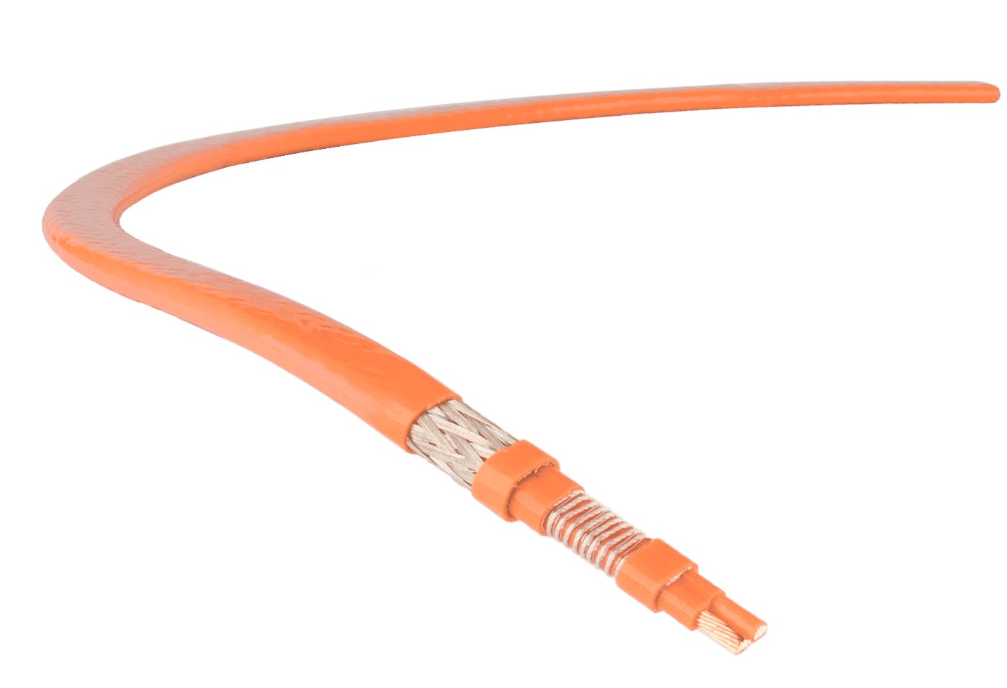
T&D stock trace heating cables in a range of technologies including self-regulating, constant wattage, mineral insulated and parallel resistance types with international hazardous area location classifications.
Should you require assistance with the supply or design of simple, custom or complex electric heating systems for acetic acid applications please do not hesitate to contact us.
Press Release Date: 02.04.2020 uploaded by Chris Dodds (T&D Sales + Marketing Manager) World’s First Fully Certified ATEX Doors Thorne & Derrick International, the Experts in Equipment for Explosive Atmospheres, today announce the signing of a Commercial Distribution Agreement...
Press Release Date: 04.07.2019 uploaded by Chris Dodds (T&D Sales + Marketing Manager) Category: Stockist Distributor Agreement Announcement Thorne & Derrick International announce that they have signed a Preferred Distributor Agreement with Raytec, the world leading manufacturer of LED...



























 T&D stock trace heating cables in a range of technologies including self-regulating, constant wattage, mineral insulated and parallel resistance types with international