Pictured Left to Right: Yves Degroote (Development Manager ATEX – Dynaco), Christian Webster-Reed (Sales Engineer – T&D), Terry McDonald (Business Development Manager – T&D), Morgan Gent (Sales Engineer – T&D) and Frank Matthys (Sales Director – Dynaco)
Press Release Date: 02.04.2020 uploaded by Chris Dodds (T&D Sales + Marketing Manager)
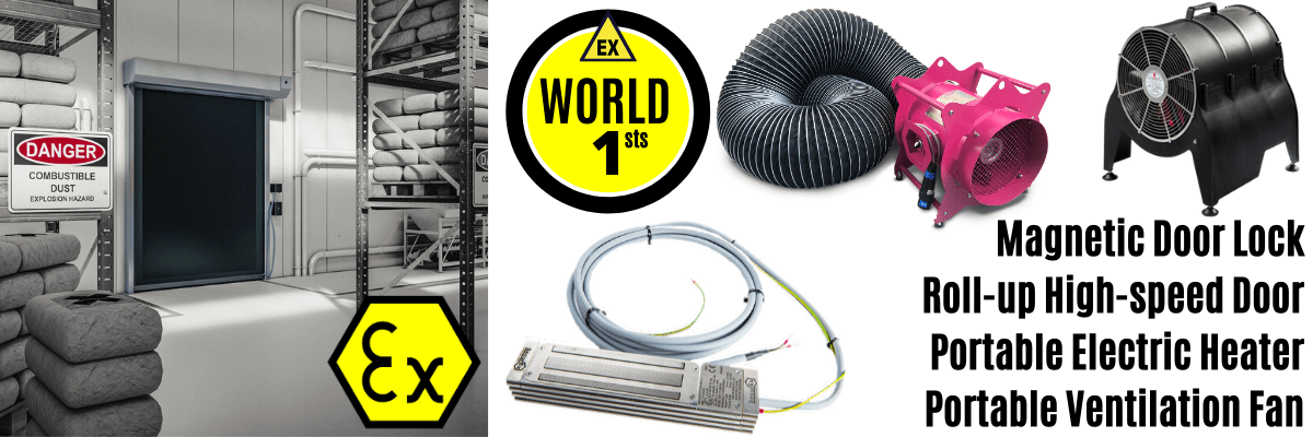
World’s First Fully Certified ATEX Doors
Thorne & Derrick International, the Experts in Equipment for Explosive Atmospheres, today announce the signing of a Commercial Distribution Agreementwith UK exclusivity for the Dynaco range of ATEX Doors suitable for hazardous areas.
Dynaco high speed roll-up doors provide significant energy efficiency and site safety improvements in the explosive atmosphere industries – this includes factories and logistics in the oil/gas, pharmaceutical, distillery, process and petrochemical sectors.
Save Energy
Reduced heat loss as a result of installing high speed doors can provide a ROI within 2 years.
Thorne & Derrick can provide energy saving calculations at point of enquiry.
💡 We can calculate your temperature losses and confirm the expected energy savings by installing high speed doors. Should you be interested to receive a FREE ROI REPORT to assess the energy efficiency impact Dynaco doors could have on your facility contact us.
The reduced heat loss also means fewer heaters or lower KW rated electric heaters in new builds. This reduces capital costs and reduces operating costs.
The Thorne & Derrick Sales Team have undergone extensive commercial and technical training at the Dynaco Academy in Belgium to support clients requirements.
“Thorne & Derrick International provide excellent coverage with the technical expertise to successfully spearhead our drive into the UK market – they are highly respected with blue-chip clients in our key sectors and we look forward to supporting them with the introduction of our ATEX certified doors to their customers,” comments Yves Degroote.
Thorne & Derrick were first introduced to Dynaco during 2018 Hazardex Exhibition and were impressed with the product.
Terry McDonald stated “The Dynaco high speed ATEX door is an innovative product which serves a niche application. Whilst there are many companies who specialise in high speed doors, none have any experience working in explosive atmospheres and such companies are unfamiliar with the strict regulations. The Dynaco ethos for safety, innovation and quality is perfectly aligned to T&Ds own strategy and I believe we can highlight a major safety issue to anyone already using such doors in an explosive atmosphere. Further, we can help end users become compliant by supplying a 3rd party certified product. For any clients wishing to install ATEX high speed doors, they can be safe in the knowledge that they will be using the safest door currently available on the market.”
Reducing Risk & Improving Safety | Energy Efficient With Provable Savings | Zones 1 (21) & 2 (22) with Flammable Gas or Dust Atmospheres
Benefits of Dynaco Doors
Explosive Atmospheres & Hazardous Area Locations & Workspaces
Save Energy – reduced heat losses to buildings achived by superior sealing against air escape, draughts, humidity and loss of heat
Fastest Door Cycle– Dynaco high speed doors limit heat loss and energy costs. 80% of energy losses are due to open time of the door
Accident Forgiving & Self Reinserting – reduce costly repairs, avoid downtime interruptions due to blocked doors + damage to vehicles
Reliability– few moving parts, reduced maintenance, lower operating costs and long service lifetime. >1million cycles = market leader
Ultra Safe – the only 3rd party ATEX certified high speed flexible door available – soft bottom with edge detection reduces accidents
Explosion Proof & Non-Sparking – high strength, corrosion-resistant stainless steel door structure + anti-static synthetic parts
Wind Load Resistance – stable and secure up to wind load class 5, according to European standards EN12424
Plant & Personnel Safety – flexible door curtain with no rigid elements improves Health & Safety with reduced site injuries + damages
Tutorial | Specifying Compliant ATEX Doors for Hazardous Areas
Dynaco
Dynaco are part of the Entrematic Group who are one of the world’s leading manufacturers of entrance automation equipment.
Dynaco specialise in high performing industrial flexible doors. Since 1987, from their manufacturing facility in Belgium, Dynaco have supplied over 170,000 doors worldwide.
Their reputation for innovation, quality and reliability is second to none and today they produce over 15,000 doors per year.
As part of their drive for innovation, Dynaco have developed the worlds first ATEX certified high speed door. Like many other door manufacturers, Dynaco were asked for an ATEX solution for use in explosive atmospheres. Unlike their competitors who were happy to supply their normal door with an ATEX motor, Dynaco were not. They rightly decided this was non-compliant with ATEX regulations and a huge safety issue for end users.
Dynaco have developed a door which utilises an ATEX motor and electrical components.
The ATEX doors are also made from non-sparking materials and anti-static PVC.
They did not stop there.
The Dynaco door is product certified by a 3rd party notified body. Each and every door is inspected prior to it leaving the factory.
If you require a door for explosive atmospheres, there is not a safer high speed door available.
Dynaco was founded by Benoit Coenraets, the inventor of the flexible roll-up door. In 2015 Dynaco launched their S-5 Atex Door.
EXPERTS IN EQUIPMENT FOR EXPLOSIVE ATMOSPHERES
leaders in ATEX Innovation To The Hazardous Area Industries
Thorne & Derrick are leaders in the development and distribution of Product Innovations that deliver significant improvements to clients plant, people and operational safety in the explosive atmosphere industries.
Your proactive problem solvers experienced in succession planning for the replacement of obsolete, non-conformant and legacy equipment in hazardous areas.
Your first-choice provider of innovative and competitive solutions to ensure ATEX & IECEx Compliance for Hazardous Area Electrical, HVAC & Process Instrumentation Equipmentto UK and international projects.
Thorne & Derrick International announce that they have signed a Preferred Distributor Agreementwith Raytec, the world leading manufacturer of LED lighting products for hazardous areas and explosive atmosphere locations.
Thorne & Derrick’s Business Development Manager Terry McDonald comments, “our expertise and knowledge of the market will prove invaluable in developing sales of Raytec hazardous area LED lights. We are currently supporting several clients undergoing workplace lighting upgrades – we are specifying, designing and supplying their switch out of conventional fluorescent into modern technology LED.”
Why Raytec?
“Partnering with Raytec as our key supplier for hazardous area LED lighting was an easy decision to make. Their hazardous area lighting products offer a safe and reliable solution to lighting requirements in explosive atmospheres. In truth there are also many other brand options in the market place but what makes Raytec stand out from the crowd is their modular design concept which has been done with end user maintenance in mind.”
“Clients are always impressed with the concept and even more so by the cost savings achievable in operational expenditure. Taking innovative solutions to clients is a key part of our strategy and I am sure the partnership with Raytec will be a long and prosperous one.”
“Our Technical Sales Team are product trained, CompEx certificated and looking forward to introducing the complete Raytec lighting range to new and existing customers,” Terry adds.
Why Thorne & Derrick?
“We’re delighted to partner with Thorne & Derrick for the distribution of our hazardous area LED lighting products. They hold years of experience in the market and have developed a strong client base which will be important in helping to open up new opportunities for us,” comments Barry Director of Hazardous Area Division.
We’re looking forward to working closely with Thorne & Derrick and are confident this will be the start of a long and successful journey together,” Barry concludes.
About Thorne & Derrick
Thorne & Derrick International, based in the UK, are Approved Vendors to most Oil & Gas exploration and production companies and international EPC contractors including Bechtel, Petrofac, Saipem and Lamprell – our key sectors are the process, pharmaceutical, chemical, utility, food/beverage, renewable and oil/gas industries.
We are the Explosive Atmosphere Expertsto COMAH-site operators adding regional and national supply chain value: providing innovative and often customised Ex solutionsengineered to improve site safety and reliability.
Lighting Hazardous Areas
💡SPARTAN LED Lighting Is Highly Energy Efficient – Less Heat, More Light, Lower Cost
Stocking SPARTAN
SPARTAN is the complete range of LED Lighting, designed and manufactured in the UK by Raytec, approved for all ATEX and IEC Ex Zone 1 and Zone 2 hazardous area locations.
SPARTAN Floodlight, Bulkhead, High Bay and Linear Light Fittings with emergency and industrial versions are available. To combine excellent customer service with the ability to deliver from stock overnight, T&D are stocking Raytec SPARTAN bulkhead, floodlight and both standard and emergency light fittings.
Innovation In Illumination
At the HazardEx 2019 awards Raytec were awarded ‘Highly Commended’ in the Technical Innovation category – their Intelligent Emergency Luminaire with automatic self-test function significantly improves the safety and reliability of emergency lighting installations in hazardous areas.
Service & Expertise
Since 1985, Thorne & Derrick have established a solid reputation for the reliable supply of leading brands across our core product groups – we have a multi-million pound stock capacity and can supply many products next day.
Thorne & Derrick at Raytec HQ UK | The Home of Hazardous Area Lighting
Pictured Left to Right: Callum Ryder (Marketing Manager – Raytec), Natalie Lundie (Social Media & SEO Marketing – T&D), Chris Dodds (Sales & Marketing Manager – T&D), Richard Derrick (MD – T&D), Terry McDonald (Business Development Manager – T&D) and Barry Thompson (Raytec – Director of Hazardous Area Division).
Further Reading
THORNE & DERRICK
LV HV Electrical & Process Instrumentation Equipment for Explosive Atmospheres
Specialist Distributors of Hazardous Area & Explosion Proof Equipment with IECEx & ATEX Certifications – we react with a rapid response to your enquiry to ensure downtime is minimised and reliable Power, Light & Heat is restored or provided.
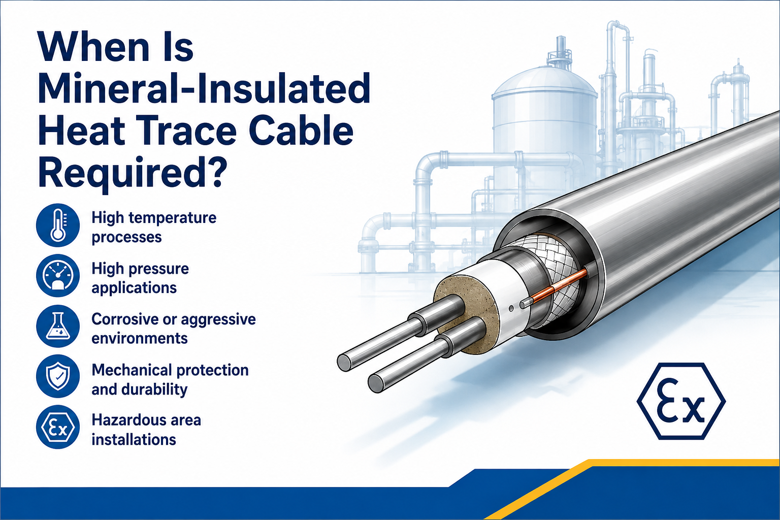
When Is Mineral-Insulated Heat Trace Cable Required?
Mineral-insulated heat trace cable is generally considered when the required temperature, power output, circuit length or operating environment exceeds the practical capability of polymeric self-regulating or constant wattage cables.
To understand where MI fits within the wider technology range, see the guide to electrical trace heating technologies. This article focuses specifically on the selection conditions that justify an MI system.
MI cable is commonly considered for:
High maintain or exposure temperatures
High power-density and controlled heat-up duties
Long engineered circuits
Severe chemical, mechanical or environmental exposure
Pipelines, vessels and equipment in demanding process plants
Hazardous-area systems requiring a suitable certified assembly
How Is Mineral-Insulated Heating Cable Constructed?
A mineral-insulated heater uses a metallic resistance conductor electrically insulated from a metal sheath by compacted mineral insulation, commonly magnesium oxide. The metal sheath provides mechanical and environmental protection while the conductor generates heat when current flows.
MI trace heaters may be supplied in single- or twin-conductor configurations and normally include engineered cold leads, joints and end terminations. The heating section is designed for the required resistance, voltage, length and output rather than cut freely from a reel on site.
Engineered Metal-Sheathed Heater
The conductor, mineral insulation, sheath, cold leads and terminations form a designed heating unit.
1. High Maintain or Exposure Temperatures
MI cable is frequently selected where the operating or exposure temperature is above the rating of suitable polymeric heating cables.
High-temperature chemical and petrochemical lines
Hot process transfer pipework
Steam-cleaned or steam-purged equipment
Bitumen, sulphur and heavy-product lines
Vessels, reactors and process equipment
Applications exposed to high temperatures while the heater is de-energised
Check Two Temperature Limits
The required maintain temperature and the maximum exposure temperature are different design values. Cable, joints, cold leads and terminations must all remain suitable for the highest credible operating, cleaning, upset or shutdown condition.
2. High Output and Controlled Heat-Up Duties
A system that must raise the temperature of a cold pipe, vessel or process product within a defined period can require substantially more power than a steady-state maintenance duty.
The starting point is an accurate heat-loss and heat-up assessment. MI cable may then be selected where a high engineered output is required and the equipment can safely accept the resulting sheath temperature.
High-output design must consider:
Steady-state heat loss
Initial and final temperatures
Product mass and specific heat capacity
Required heat-up time
Maximum permissible surface and sheath temperatures
Cable spacing and heat distribution
Temperature control and independent limiting
3. Long Circuits and Engineered Resistance
MI heating cable is a series-resistance heater. Its resistance, length, conductor material and supply voltage are selected together to produce the required output.
This engineered approach can be useful for long pipe runs or duties where parallel-circuit cable limits would require multiple shorter circuits. However, a long MI circuit is not automatically the best solution; voltage, output distribution, cold leads, power supplies and control architecture must all be assessed.
4. Harsh Industrial Environments
The metal sheath and mineral insulation can provide strong resistance to heat, fire and mechanical damage. Different sheath alloys are available for different corrosive environments.
Environmental Requirement
Why MI May Be Considered
High ambient or process heat
Metal and mineral construction can tolerate temperatures beyond many polymeric cables
Mechanical exposure
Metal sheath provides robust protection, subject to routing and bend-radius limits
Chemical or corrosive atmosphere
A suitable sheath alloy can be selected for the environment
Fire resistance
Inorganic insulation and metal construction offer strong high-temperature stability
Outdoor or offshore service
Engineered sheath, joints and terminations can suit severe environments
High-pressure or critical process plant
Factory-engineered assemblies provide controlled resistance and documented construction
Sheath selection must be based on the actual chemical exposure. No single metal alloy is universally resistant to every acid, chloride, sulphur compound or process contaminant.
5. Mineral-Insulated Trace Heating in Hazardous Areas
MI heaters are available as certified systems for explosive atmospheres, but the complete assembly must be selected and installed for the area classification.
Area classification and equipment protection level
Gas or dust group
Temperature class or maximum surface temperature
Stabilised design or controlled design method
Approved joints, cold leads, glands and enclosures
Controller and independent temperature limiter requirements
Ambient, maintain and exposure temperatures
View the ATEX trace heating range and obtain technical confirmation for the proposed MI assembly.
MI Cable Compared with Self-Regulating and Constant Wattage Cable
Selection Factor
Mineral-Insulated
Self-Regulating
Constant Wattage / Resistance
Typical reason for selection
High temperature, high output, long engineered circuit or severe environment
Variable-temperature response and convenient field installation
Defined output and controlled process heating
Construction
Metal conductor, mineral insulation and metal sheath
Parallel bus wires with conductive polymer core
Parallel heating zones or series resistance conductor
Field cutting
Normally supplied as an engineered heater unit
Usually cut to length within product limits
Depends on parallel-zone intervals or engineered series length
MI cable should not be specified simply because it is the most robust or highest-temperature technology available.
Low-temperature frost protection may be served more simply by self-regulating cable
A standard process-maintenance duty may fall comfortably within a polymeric cable range
Complex valves and fittings may be easier to trace with a flexible parallel cable
Projects requiring simple cut-to-length field installation may favour self-regulating or parallel-zone cable
High output may be unnecessary when insulation can be improved
The pipe or product may not tolerate the surface temperature associated with a high-output MI design
Select the Lowest Suitable Technology
The preferred cable is the one that meets the thermal, electrical, environmental and certification requirements with appropriate control—not automatically the cable with the highest temperature or output rating.
MI Trace Heating Design and Installation Considerations
Calculate the duty: establish steady-state heat loss and any heat-up requirement.
Confirm temperatures: maintain, maximum exposure, ambient and permitted sheath temperatures.
Select sheath material: match the alloy to the chemical and mechanical environment.
Design resistance and length: coordinate voltage, conductor resistance, cable length and output.
Plan cold leads and joints: position transitions and enclosures within their temperature limits.
Specify control and limiting: use sensors, controllers and independent limiters where required.
Check installation geometry: bend radius, spacing, attachment and heat distribution are critical.
Test throughout installation: complete the specified resistance and insulation checks before and after insulation.
Document the heater: retain factory data, circuit drawings, settings and commissioning readings.
No. High temperature is a common reason for selecting MI, but high output, long engineered circuits, fire resistance, mechanical strength and chemical resistance can also influence the decision.
Can Mineral-Insulated Heating Cable Be Cut to Length on Site?
MI heaters are normally designed and manufactured to a specific resistance, length, voltage and output. They should not be treated as bulk cut-to-length parallel cable.
Does MI Cable Require a Thermostat?
A suitable controller is normally required, and an independent temperature limiter may also be necessary where maximum sheath or surface temperature must be controlled. The exact arrangement comes from the system design.
Can MI Heating Cable Be Used in Hazardous Areas?
Yes, certified MI heater systems are available. The complete assembly, controls, terminations and installation must match the area classification and certification conditions.
Is MI Cable More Durable Than Polymeric Heating Cable?
Its metal sheath and inorganic insulation can provide excellent heat, fire and mechanical resistance. Durability still depends on choosing the correct sheath alloy, installing it within bend limits and protecting joints and terminations.
When Should Self-Regulating Cable Be Chosen Instead?
Self-regulating cable may be more suitable for lower-temperature frost protection, irregular pipework, changing ambient conditions and projects requiring straightforward cut-to-length installation.
Need an Engineered MI Trace Heating System?
Thorne & Derrick supports mineral-insulated heating cable selection for high-temperature, high-output, long-line and hazardous-area applications.
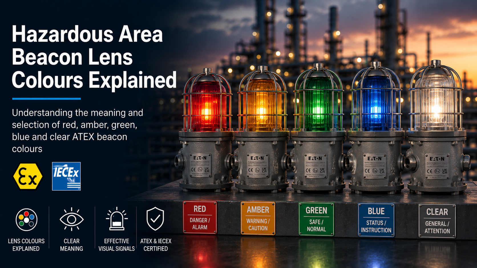
Hazardous area beacon lens colours help personnel distinguish between alarms, warnings, equipment states and process conditions. Red, amber, green, blue and clear signals can each communicate a different message when used within a properly defined alarm philosophy.
However, a beacon colour does not have one fixed meaning in every industry or on every site. The intended response should be established through the project specification, operating procedures and site-specific visual signalling system.
Thorne & Derrick supplies hazardous area ATEX beacons in a range of lens and signal colours, with LED, xenon, steady, flashing, strobe and electronically rotating options.
For a general introduction to hazardous area visual signalling, read What Is an ATEX Beacon?
Key principle: select the beacon colour from the documented site alarm philosophy. Do not assume that a colour automatically represents the same condition across every plant, industry or country.
The table below summarises common industrial interpretations. These meanings are indicative only and must be checked against the site alarm philosophy.
Beacon Colour
Common Interpretation
Example Applications
Required Response
Red
Danger, emergency, serious alarm or stop condition
Fire alarm, gas alarm, emergency shutdown or hazardous machine state
Immediate attention or action may be required
Amber or Yellow
Warning, caution, abnormal condition or awareness
Equipment about to start, process deviation, restricted area or potential hazard
Check conditions and proceed with caution
Green
Normal, safe, available, ready or action completed
Equipment operating normally, safe access or alarm acknowledged
Normal operation or a safe condition may be indicated
Blue
Change, specific status, instruction or security-related condition
Equipment powering down, security alarm or site-specific process state
Follow the documented site instruction
Clear or White
General attention, location, visibility or project-specific indication
General notification, obstruction indication or equipment identification
Confirm the intended meaning from the site documentation
Do not rely on this table alone: the signal meaning should be formally defined, documented and communicated to site personnel. A manufacturer’s available colour does not determine how it must be used.
What Does a Red Beacon Indicate?
Red is commonly associated with danger, emergency, fire, a serious process alarm or a condition requiring immediate attention.
A flashing red beacon generally creates a stronger warning message than a steady red signal. However, the response must be determined by the documented alarm system rather than the colour and signal mode alone.
Common Red-Beacon Applications
Fire or gas detection alarm
Emergency shutdown condition
Evacuation warning
Dangerous machine or process state
Live or energised equipment warning
Critical fault requiring immediate response
Avoid conflicting meanings: if red is reserved for fire or evacuation alarms, it should not also be used for routine equipment status without a clear and documented distinction.
What Does an Amber or Yellow Beacon Indicate?
Amber and yellow are commonly used for warnings, caution, abnormal conditions or situations requiring increased awareness.
The signal may indicate that equipment is about to start, a process is outside its normal range or a potential hazard is developing but has not reached an emergency condition.
Common Amber-Beacon Applications
Machinery preparing to start or move
Process deviation or developing fault
Temporary restriction or caution area
Reduced visibility or environmental warning
Maintenance or inspection attention required
Non-critical plant alarm
Amber vs Yellow
Manufacturers do not always use amber and yellow terminology in exactly the same way. One datasheet may describe the lens as amber while another refers to the corresponding emitted LED colour as yellow.
Always use the exact manufacturer colour description and ordering code when requesting a quotation.
What Does a Green Beacon Indicate?
Green is commonly used to indicate a normal, safe, available or correctly operating condition.
It can also show that an alarm has been acknowledged, corrective action is under way or equipment is ready for operation.
Common Green-Beacon Applications
Normal equipment operation
Safe access or safe process condition
System ready or available
Corrective action completed
Alarm condition acknowledged or controlled
Plant status within defined operating limits
Green should not be used where personnel could mistake it for an unrestricted safe condition when a residual hazard remains.
What Does a Blue Beacon Indicate?
Blue is often used for a specific instruction, change in condition, security-related alarm or site-defined process state.
Its meaning can be particularly site-specific. Personnel should therefore be trained to understand the response required when a blue signal is activated.
Possible Blue-Beacon Applications
Equipment powering down or changing state
Security or access-control alarm
Operator action required
Specific maintenance or process condition
A signal that must remain distinct from red, amber and green conventions
External restrictions may apply: blue warning lights can have regulated meanings in transport and emergency-service environments. Check the installation location and applicable rules before selection.
Clear Beacon Lens vs White Signal
“Clear” and “white” do not always describe the same component.
A clear or transparent lens describes the colour of the dome or cap. A white signal describes the light emitted by the LED, lamp or flash source.
A clear lens may therefore be used with a white LED, xenon flash tube or another internal light source, depending on the product.
Common Clear or White Applications
General attention or notification
Equipment or obstruction indication
Long-distance or high-visibility signal
Area or equipment identification
Project-specific alarm condition
Clear or white should not be treated as a neutral default without confirming what the signal is intended to communicate.
How Colour and Signal Mode Work Together
Personnel interpret the complete visual signal rather than the lens colour in isolation. A steady red light can communicate a different level of urgency from a rapidly flashing red strobe.
The meaning can be strengthened by combining colour with:
Steady, blinking, strobe or rotating signal modes
Different flash or rotation frequencies
Audible alarm tones
Text labels and identification plates
Symbols or display messages
Beacon position or location
Colour should be supported by these supplementary methods where relying on colour alone could create ambiguity.
Do LED and Xenon Beacons Produce Colour Differently?
Yes. The method used to create the coloured signal can differ between LED and xenon products.
LED Beacon Colours
An LED beacon can use coloured LEDs, a coloured cap or a combination of the two. The wavelength, brightness and current consumption can vary between colours.
Xenon Beacon Colours
A xenon flash tube produces a broad-spectrum pulse of light. A coloured dome or lens filters that light to create the required signal colour.
The filtering effect can reduce the measured optical intensity compared with a clear lens. The reduction is product- and colour-specific.
Colour can affect the apparent brightness, contrast and recognition of a beacon signal.
Visibility is influenced by:
The LED, lamp or xenon flash output
Lens colour and light transmission
Viewing distance
Direct sunlight and ambient illumination
Background colour and visual contrast
Mounting height and orientation
Structures or equipment obstructing the signal
Flash frequency or signal pattern
The observer’s position and field of view
Product-specific performance: do not assume that one colour is always brighter than another. Current Eaton FHF dSLB20 LED data, for example, gives different approximate optical outputs for white, red, yellow, green and blue versions.
Should an Alarm Depend on Colour Alone?
Where a warning is safety-critical, the meaning should not depend unnecessarily on colour alone.
Lighting conditions, smoke, dirt, distance and differences in colour perception can all affect how the signal is recognised.
Confirm colour availability against the current product datasheet and complete ordering code. Not every colour is available for every voltage, signal mode or approval.
How to Select a Hazardous Area Beacon Colour
Colour selection should take place after the hazardous area and technical requirements have been established.
Confirm the site alarm philosophy. Identify what each colour already represents and avoid introducing conflicting meanings.
Define the required response. Establish whether personnel must stop, evacuate, investigate, acknowledge or continue normal operation.
Select the signal mode. Decide whether the condition requires steady, blinking, strobe or rotating indication.
Include the following information when requesting a quotation:
Hazardous area zone
Gas or combustible-dust group
Temperature class and ambient range
LED, xenon or alternative technology
Steady, flashing, strobe or rotating mode
Required signal or lens colour
Operating voltage
Indoor, outdoor or offshore environment
Viewing distance and ambient lighting
Mounting and cable-entry requirements
Common Beacon Colour Selection Mistakes
Assuming that every site uses identical colour meanings
Selecting a colour before defining the required operator response
Using the same colour for emergency alarms and routine equipment status
Assuming that every colour produces the same optical intensity
Failing to distinguish between a clear lens and a white emitted signal
Relying on colour without a supplementary signal or documented procedure
Failing to confirm colour availability for the required voltage and certification
Hazardous Area Beacon Colour FAQs
Does a red beacon always mean fire?
No. Red commonly indicates danger or emergency, but its exact meaning must be defined by the site alarm philosophy. Some sites reserve red specifically for fire or evacuation.
Are amber and yellow the same beacon colour?
They are frequently grouped as caution or warning colours, but manufacturer terminology and exact optical characteristics can differ. Use the stated ordering colour and code.
Does a clear lens produce white light?
It can, but not automatically. Clear describes the lens or cap, while white describes the emitted light. Check the light source and product configuration.
Does lens colour affect beacon brightness?
Yes. Lens filtering and LED wavelength can affect the measured and apparent output. Check the manufacturer’s data for the exact colour.
Can different beacon colours use the same flash pattern?
Yes, but personnel must still be able to distinguish the intended conditions. Similar patterns and poor colour contrast can create confusion.
Does the lens colour determine the hazardous area zone?
No. Zone suitability is determined by the complete certification and equipment marking. Lens colour affects the visual signal but does not establish the hazardous area classification.
Need Help Selecting a Beacon Colour?
Send Thorne & Derrick the hazardous area classification, intended alarm meaning, signal mode, viewing conditions, voltage and required colour for product selection support.
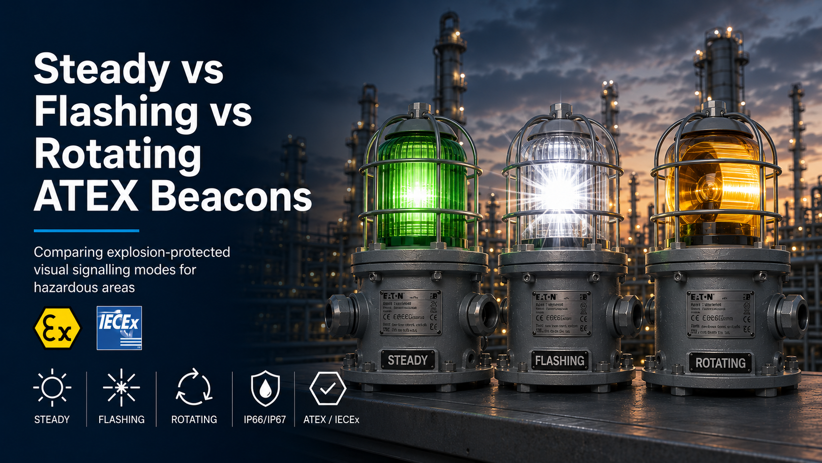
Steady, flashing, strobe and rotating beacons communicate different types of warning and status information. Although each produces a visible signal, the way that signal attracts attention and conveys meaning can vary considerably.
A steady beacon provides continuous illumination. A flashing beacon switches between illuminated and non-illuminated states. A strobe beacon produces brief, high-intensity pulses, while a rotating beacon creates the appearance of a moving light.
Thorne & Derrick supplies a comprehensive range of hazardous area ATEX beacons with steady, blinking, strobe, xenon-flash and electronically rotating visual signals.
Quick answer: use steady illumination for persistent status indication, flashing or strobe signals where increased attention is required, and rotating signals where a distinctive moving visual warning supports the site alarm philosophy.
Steady vs Flashing vs Rotating Beacons: Quick Comparison
Signal Mode
Visual Behaviour
Typical Purpose
Important Selection Data
Steady
Continuous illumination
Persistent equipment, plant or process status
Optical output, colour, viewing distance and continuous-duty rating
Flashing or Blinking
Repeating on-and-off pattern
Warning, changing condition or attention signal
Flash frequency, duty cycle, colour and control method
Strobe
Brief, rapid or high-intensity pulses
Prominent alarm or emergency warning
Flash energy or optical intensity, frequency and current consumption
Rotating
Moving beam or electronically sequenced segments
Distinctive warning or recognisable plant-status signal
Rotation rate, field of view, mechanism and maintenance requirements
Important: the most attention-grabbing signal is not automatically the correct choice. The selected mode must agree with the site alarm philosophy and remain distinguishable from other alarms and equipment-status indicators.
When Should a Steady Beacon Be Used?
A steady beacon remains illuminated while the electrical supply or control signal is present. It provides a continuous reference rather than repeatedly attracting attention through movement or flashing.
This makes steady signalling particularly useful for showing a persistent operating state or condition.
Typical Steady-Beacon Applications
Equipment running or stopped indication
Valve open or closed status
Process available, isolated or inhibited condition
Persistent local warning
Plant or machinery status indication
A visual signal designed to remain active for an extended period
Advantages of Steady Illumination
Provides a constant visual reference
Suitable for persistent process and equipment states
Can be easier to interpret where several flashing alarms are present
Available using filament, fluorescent or LED technologies, depending on the product
Limitations of a Steady Signal
Continuous illumination may attract less immediate attention than a changing or moving signal. A steady beacon can also become part of the visual background where several continuously illuminated indicators are present.
Viewing distance, mounting position, lens colour and contrast against the surrounding environment should therefore be assessed.
When Should a Flashing or Blinking Beacon Be Used?
A flashing or blinking beacon changes between illuminated and non-illuminated states at a defined frequency. The changing light level can attract more attention than a steady signal.
In many LED products, the pattern is produced electronically. The flash rate may be fixed or selected from the modes available within the product.
Typical Flashing-Beacon Applications
Process alarm or fault condition
Equipment trip or abnormal status
Gas, fire or evacuation warning
Attention signal before machinery starts
Condition requiring operator acknowledgement
Flash Frequency
Flash frequency describes how often the signal repeats. The correct frequency should be determined by the product capability and site alarm philosophy.
Two alarms with similar colours and flash frequencies may be difficult to distinguish. Signal patterns should therefore be coordinated across the installation.
What Is the Difference Between Flashing and Strobe?
“Flashing” is a broad description for a light that repeatedly switches on and off. A strobe is a more specific type of flashing signal that produces brief and often high-intensity pulses.
A xenon strobe discharges stored electrical energy through a xenon flash tube. Its output is commonly specified using flash energy in joules and flash frequency.
An LED strobe creates its pulse electronically. Its optical performance is not automatically equivalent to a xenon flash with a stated joule rating.
A rotating beacon creates a moving visual signal that appears to sweep around the installation. This movement can make the signal recognisable even where several fixed lights are present.
Rotating signals can be produced mechanically or electronically.
Mechanically Rotating Beacons
A mechanically rotating design uses a motor and rotating reflector or light assembly to direct the beam around the beacon.
Rotation speed, motor life and moving-part maintenance should be considered when specifying this type of product.
Electronically Rotating LED Beacons
An electronically rotating beacon illuminates LED segments in sequence. This creates the appearance of movement without a motor-driven reflector.
Different electronic rotation patterns or speeds may be available, depending on the model.
Typical Rotating-Beacon Applications
Distinctive plant or machinery warning
Vehicle, loading or movement indication
Process condition requiring a recognisable moving signal
Replacement of an established rotating-beacon alarm convention
Which Signal Is Most Visible?
No single signal mode is the most visible under every condition. Visibility depends on the product output, signal pattern and installation environment.
Consider:
Viewing distance
Ambient lighting and direct sunlight
Mounting height and orientation
Structures and process equipment that may obstruct the signal
Required horizontal and vertical field of view
Lens or LED colour
Flash or rotation frequency
Other visual signals in the same area
The product should be positioned so that the intended audience can see and interpret the signal from the required working locations.
Does Each Signal Mode Have a Fixed Meaning?
A signal mode does not automatically carry one universal meaning across every site. Its purpose should be defined within the alarm philosophy, operating procedure or project specification.
For example, one installation may use steady illumination for normal equipment status and flashing red for an alarm. Another site may reserve flashing signals for evacuation and use rotating amber for machinery movement.
The meaning must therefore be documented, communicated to personnel and applied consistently.
How Does Lens Colour Affect the Signal?
Lens or LED colour helps distinguish between alarm and status conditions, but it can also affect the apparent optical output.
The visibility of red, amber, green, blue, yellow or clear signals can differ according to the light source, lens construction and surrounding lighting.
Manufacturer performance data should be checked for the exact ordered colour.
Electrical Supply and Control Considerations
Signal mode can affect the beacon’s current consumption and control requirements. The exact electrical data should be checked for the selected voltage, colour and operating pattern.
Confirm:
Nominal operating voltage
Permitted voltage range
Current consumption for the selected mode
Control-panel or relay capacity
Whether the mode is fixed or internally selectable
Whether remote switching between modes is required
Required fault monitoring or end-of-line arrangements
Check the ordered variant: a product family may offer several modes, but this does not necessarily mean that every configuration can change modes remotely while in service.
Does the Signal Mode Affect Hazardous Area Suitability?
The visual signal alone does not determine whether a beacon is suitable for an explosive atmosphere. The complete certified construction and equipment marking must match the installation.
Check:
Hazardous area zone
Gas or combustible-dust group
Equipment category and equipment protection level
Explosion-protection concept
Temperature class or maximum surface temperature
Permitted ambient-temperature range
Required ATEX, UKEX, IECEx or destination-market approval
These products illustrate different signal behaviours. The complete technical and certification requirements must still be checked for each application.
Steady Visual Signal
The MEDC FB11 filament and FL11 fluorescent units provide steady illumination for persistent warning or status indication.
Selection should begin with the hazardous area and site alarm requirements rather than a preference for the most visually dramatic product.
Requirement
Signal to Consider
Reason
Persistent equipment or process state
Steady
Provides continuous status indication
Abnormal condition requiring attention
Flashing or Blinking
Changing signal can attract attention
Defined high-intensity pulsed warning
Strobe
Produces brief and distinctive visual pulses
Recognisable moving visual signal
Rotating
Creates an identifiable sweeping or sequenced effect
For the complete selection process, including zone, certification, temperature, voltage and environmental conditions, read How to Select an ATEX Beacon.
Common Signal-Mode Selection Mistakes
Selecting the most intense signal without considering the required alarm meaning
Using several similar flash patterns that personnel cannot easily distinguish
Assuming a rotating LED signal uses a mechanical motor and reflector
Treating an LED strobe as directly equivalent to a xenon flash-energy rating
Ignoring the effect of sunlight, obstructions and mounting height on visibility
Choosing signal mode before confirming hazardous area certification and temperature limits
Should a Visual Signal Be Supported by a Sounder?
A beacon may form only one part of the alarm arrangement. Audible and visual signals are often combined where personnel may not always be looking towards the beacon or where high noise, hearing protection or visibility restrictions affect alarm recognition.
The alarm design should establish whether a beacon, sounder or combined unit is required.
Is a flashing beacon more visible than a steady beacon?
A changing signal can attract more attention, but actual visibility depends on optical output, viewing distance, colour, ambient lighting, mounting position and surrounding visual conditions.
Is a strobe the same as a flashing beacon?
A strobe is a type of flashing signal characterised by brief pulses. The term flashing can also describe slower or less intense on-and-off patterns.
Does an electronically rotating beacon contain moving parts?
Normally, no. Electronically rotating products create the effect by illuminating LED segments in sequence rather than using a motor-driven reflector.
Can one beacon provide several signal modes?
Some LED products provide several internally selectable modes. Confirm whether the selected variant supports the required patterns and whether they are chosen during installation or controlled remotely.
Which mode is best for process status?
Steady illumination is commonly suited to persistent status indication. Flashing or rotating modes may be more appropriate where the condition needs to attract immediate attention.
Does a beacon mode determine its hazardous area zone?
No. Zone suitability is determined by the complete equipment certification and marking, not by whether the visual signal is steady, flashing or rotating.
Need Help Selecting a Beacon Signal Mode?
Send Thorne & Derrick the hazardous area classification, required alarm behaviour, viewing conditions, voltage, colour and installation environment for product selection support.
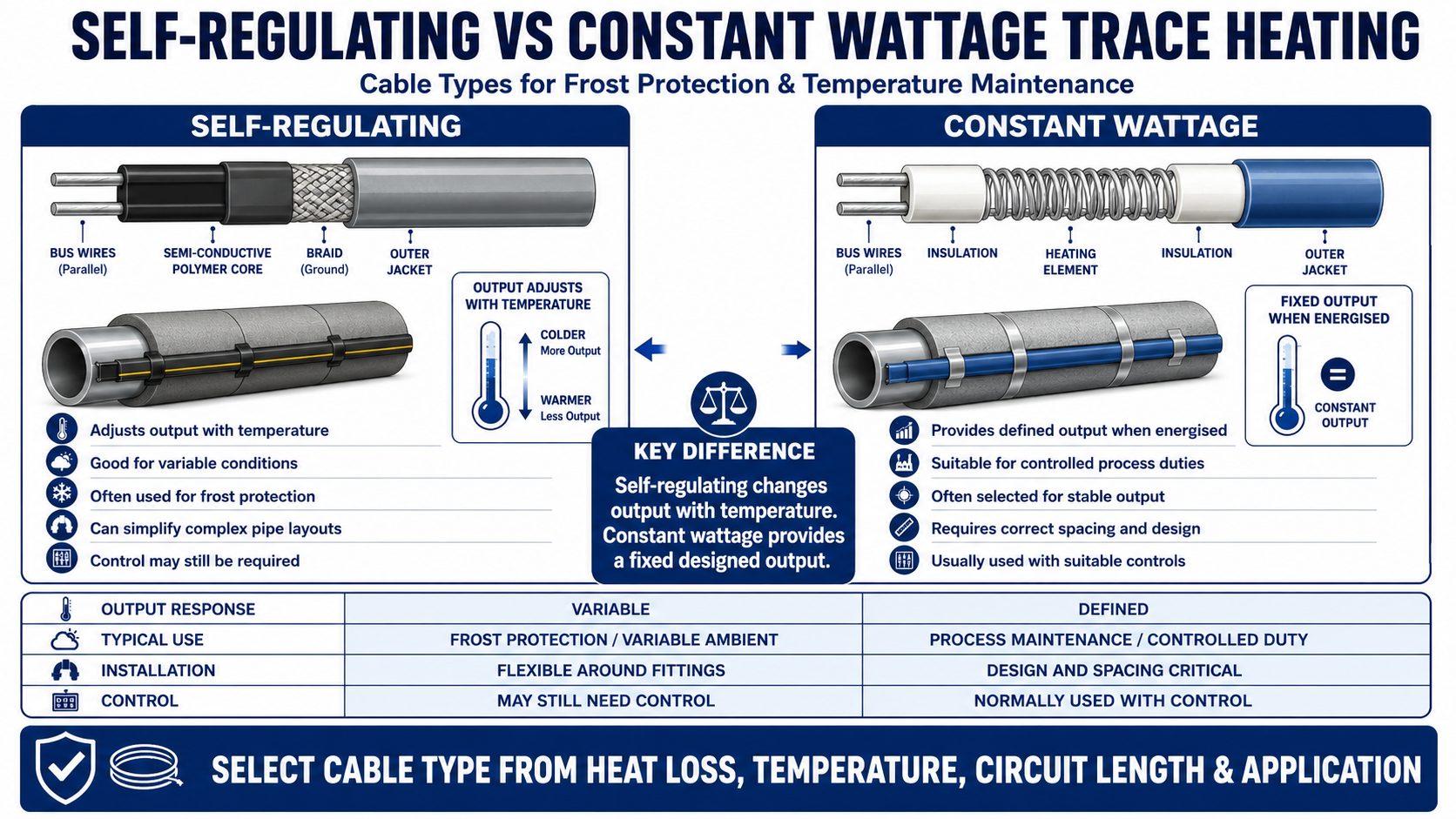
Self-Regulating vs Constant Wattage Trace Heating: Overview
Self-regulating vs constant wattage trace heating is a cable-technology comparison. Both can provide frost protection and process temperature maintenance, but they regulate output differently and have different installation, control and temperature capabilities.
For a broad introduction to the complete system, read how electrical trace heating works. This article concentrates only on the differences that affect cable selection.
The decision should consider:
Calculated heat loss and required watts per metre
Maintain and maximum exposure temperatures
Pipe or equipment material
Required circuit length and supply voltage
Need for precise temperature control
Likelihood of cable crossing or complex fittings
Safe-area or hazardous-area classification
Energy, maintenance and lifecycle requirements
What Is the Key Difference?
Cable Type
How Output Behaves
Self-regulating
Electrical resistance within the conductive core changes locally with temperature, so heat output increases as the cable cools and decreases as it warms.
Constant wattage
The heating circuit provides a defined output when energised. Temperature is managed through system design and suitable control equipment rather than local self-regulation.
Important Distinction
Self-regulating does not mean that every system can operate without a thermostat, controller or limiter. Control may still be required for process accuracy, energy management, alarms, equipment protection or hazardous-area temperature classification.
How Does Self-Regulating Trace Heating Cable Work?
A self-regulating cable normally contains two parallel bus wires embedded in a conductive polymer heating core. As the local temperature changes, the resistance of the core changes and alters the heat generated at that point along the cable.
Colder areas of the cable can produce more heat
Warmer areas reduce their heat output
The cable can usually be cut to the required length within its product limitations
Local output response can help with irregular pipework and changing ambient conditions
Many products permit limited overlap, but only where the manufacturer explicitly allows it
How Does Constant Wattage Trace Heating Cable Work?
Constant wattage cables use a resistance heating element to deliver a defined power output while energised. Parallel-zone designs contain repeated heating zones, while series-resistance cables are engineered to a specific circuit resistance and length.
Output does not automatically reduce locally as the surface warms
A suitable control method is normally required
Parallel-zone cable is cut only at the permitted contact or module intervals
Series-resistance cable output depends on its designed length, resistance and supply voltage
Cable crossing or overlap is generally prohibited unless specifically approved
Self-Regulating and Constant Wattage Cable Comparison
Selection Factor
Self-Regulating Cable
Constant Wattage Cable
Output response
Varies locally with cable temperature
Defined output while energised
Cut-to-length
Usually cut to length within maximum circuit limits
Parallel-zone types cut at contact intervals; series types are engineered lengths
Overlap
Some products permit overlap subject to instructions
Normally must not touch, cross or overlap unless specifically approved
Temperature control
May still require control depending on duty
Normally requires suitable thermostatic or electronic control
Complex fittings
Often convenient around valves, flanges and irregular surfaces
Requires careful spacing and routing to prevent local overheating
Energy behaviour
Output reduces as the cable warms
Energy use is governed mainly by output, operating time and control strategy
Temperature capability
Available across low, medium and some high-temperature duties
Available for wider specialist or higher-temperature duties depending on construction
Circuit design
Maximum circuit length affected by cable, voltage, start-up temperature and protection
Affected by cable construction, zone spacing, resistance, voltage and control
Typical selection reason
Variable ambient conditions, simple field installation and frost protection
Stable output, specific process duty or temperature range
Heat Output and Temperature Control
Neither technology should be selected from its nominal watts-per-metre rating alone. The required output should first be established through a trace heating heat loss calculation.
For self-regulating cable, confirm the output available at the required maintain temperature using the manufacturer’s power-output curves or design software. The nominal output may be stated at a different reference temperature.
For constant wattage cable, confirm that the fixed output and control arrangement can maintain the required temperature without exceeding the pipe, product, cable or area-classification limits.
Control Options
Ambient-sensing thermostat for basic frost-protection groups
Pipe-sensing thermostat for direct temperature maintenance
Electronic controller for improved accuracy, alarms and monitoring
Independent temperature limiter where a maximum surface temperature must not be exceeded
Multi-circuit control panel for larger industrial systems
Installation and Circuit Design Differences
Installation convenience depends on the cable construction, pipework layout and approved accessory system.
Design Point
Self-Regulating
Constant Wattage
Valves and flanges
Flexible routing and permitted overlap may simplify allowances
Spacing and contact must be carefully controlled
Branching
Approved splice and tee components are used where permitted
Must follow the cable’s zone or circuit design
Long circuits
Maximum length can be limited by start-up current
Parallel or series designs may suit different long-line duties
Termination
Field termination kits are commonly available
Termination depends on parallel-zone or engineered series construction
Protection
Circuit-breaker and earth-fault selection must consider start-up behaviour
Protection must match designed current, output and control method
Repair
Approved field repair systems may be available
Repairability depends strongly on the cable construction
Longer industrial pipe circuits where a suitable design is available
Tanks, vessels, silos and specialist equipment
Applications using detailed thermostatic or electronic control
Projects where cable construction and chemical resistance match a demanding environment
These are general patterns rather than automatic choices. The correct technology depends on the calculated duty and the performance limits of the individual cable.
Energy Use, Reliability and Maintenance
Self-regulating cable can reduce local output as temperatures rise, but total energy use still depends on cable output, circuit length, insulation, control strategy and operating time.
A constant wattage system can also operate efficiently when correctly sized and controlled. Oversizing either technology or operating it continuously when heat is not required can increase energy consumption.
Lifecycle considerations:
Quality and condition of thermal insulation
Accessibility of power connections and terminations
Availability of compatible replacement components
Controller accuracy and alarm capability
Exposure to chemicals, moisture and mechanical damage
Required inspection and maintenance intervals
Self-Regulating and Constant Wattage Cables in Hazardous Areas
Both technologies may be available as certified systems for explosive atmospheres. Selection must address more than the cable certificate.
Area classification and equipment protection level
Gas or dust group
Temperature class or maximum surface temperature
Ambient and exposure temperature range
Approved power connections, terminations, splices and junction boxes
Control and limiting method
Installation, inspection and maintenance requirements
Low-temperature frost protection with variable ambient conditions
Self-regulating
Complex pipe fittings and field cut-to-length installation
Self-regulating
Defined process output with active temperature control
Constant wattage
Higher temperature or specialist industrial duty
Constant wattage or mineral-insulated, subject to design
Very high temperature, high output or severe mechanical environment
Mineral-insulated may be required
Long pipeline
Cable technology should be selected from heat loss, voltage, circuit length and control requirements
The table is a starting point only. Product data, design software and technical review are required before final specification.
Information Required Before Comparing Cable Types
Provide the following design data:
Frost protection or process temperature-maintenance duty
Required maintain and maximum exposure temperatures
Minimum ambient temperature
Pipe diameter, material and length
Insulation material and thickness
Valves, flanges, pumps and other local heat sinks
Available voltage and preferred circuit arrangement
Safe-area or hazardous-area classification
Required control, alarm and monitoring functions
Environmental, chemical and mechanical exposure
Self-Regulating vs Constant Wattage Trace Heating FAQs
Is Self-Regulating Cable Always More Energy Efficient?
It can reduce its local output as temperature rises, but total system efficiency also depends on correct sizing, insulation, control, circuit length and operating time. A correctly designed constant wattage system can also be efficient.
Does Self-Regulating Mean No Thermostat Is Required?
No. A thermostat, controller or limiter may still be required for process accuracy, energy management, alarms, equipment protection or hazardous-area temperature control.
Can Constant Wattage Cable Be Cut to Any Length?
Not always. Parallel-zone cable is cut at defined contact intervals, while series-resistance cable is designed to a specific length and resistance. Follow the individual product instructions.
Can Trace Heating Cable Be Overlapped?
Some self-regulating products allow overlap within their stated limits. Constant wattage and series-resistance cables generally must not touch or overlap unless the manufacturer explicitly approves it.
Which Cable Is Better for Frost Protection?
Self-regulating cable is commonly selected because it responds to local temperature and can be convenient to install. The final choice still depends on heat loss, pipe material, circuit length, environment and approvals.
Which Cable Is Better for High-Temperature Process Heating?
Constant wattage, series-resistance or mineral-insulated cable may offer suitable temperature capability, but the selection depends on maintain temperature, exposure temperature, output, circuit length and environment.
Need Help Comparing Trace Heating Cable Types?
Thorne & Derrick provides heat-loss calculation, cable selection and complete electrical heat tracing system support for frost protection, process maintenance and hazardous areas.
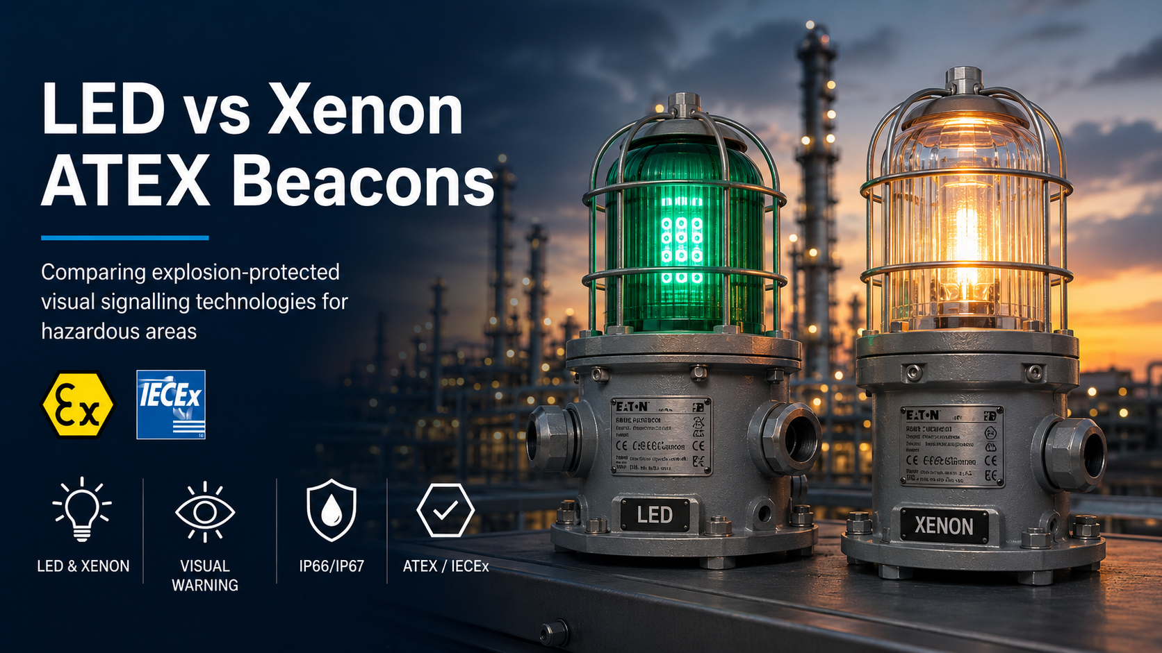
LED and xenon are two of the principal light-source technologies used in hazardous area visual signalling. Both can provide an effective warning, but they produce different signal patterns and are selected using different performance criteria.
An LED ATEX beacon can provide continuous or electronically controlled signalling, depending on the model. A xenon ATEX beacon uses a flash tube to produce a brief, high-intensity pulse and is normally specified by its flash energy in joules.
Thorne & Derrick supplies a comprehensive range of ATEX beacons incorporating LED, xenon, steady, flashing, strobe and electronically rotating visual signals. For a wider introduction to hazardous area visual signalling, read What Is an ATEX Beacon?
Quick answer: select LED where configurable signal modes, continuous indication or long solid-state operating life are priorities. Consider xenon where the specification calls for a defined high-intensity flash measured in joules. Certification and application suitability must be confirmed separately.
Steady, blinking, strobe or electronically rotating, depending on model
Brief, high-intensity flashing signal
Common performance data
Optical intensity, operating pattern, frequency and current consumption
Flash energy in joules, flash frequency and current consumption
Continuous indication
Available on suitable models
Not the normal function of a xenon strobe
Configurable modes
Multiple electronic modes may be available
Normally a defined flash pattern
Service consideration
Solid-state light source with no xenon flash tube
Flash-tube operating life should be considered
Typical reason for selection
Flexible signalling, steady status indication or electronic rotating effect
Defined high-intensity pulsed warning
Important comparison point: an LED beacon’s optical output and a xenon beacon’s flash energy are not directly interchangeable measurements. A stated number of joules should not be compared directly with a candela or lumen figure.
How Does an LED Hazardous Area Beacon Work?
An LED beacon uses an array of light-emitting diodes to generate the required visual signal. The LEDs may remain continuously illuminated or be controlled electronically to create blinking, pulsed or rotating effects.
The exact capabilities depend on the product. Some models provide only a single steady or flashing output, while others offer several modes selected during installation.
Typical LED Operating Modes
Steady: continuous illumination for a persistent warning or equipment-status signal
Blinking: a regular electronic on-and-off pattern
Strobe: a rapid sequence of electronically controlled LED pulses
Electronically rotating: LED segments illuminate in sequence to create the appearance of movement
Advantages of LED Signalling
Multiple signal patterns may be available from one product platform
Continuous visual indication can be provided
Solid-state light source with no mechanical rotating assembly
Suitable for alarm, notification and process-status applications
Long operating life may reduce routine light-source replacement
These advantages should not be treated as universal. The actual power consumption, visibility, operating life and available modes depend on the selected model, voltage and colour.
How Does a Xenon Hazardous Area Beacon Work?
A xenon beacon stores electrical energy and discharges it through a xenon-filled flash tube. This creates a brief, intense pulse of light.
Xenon strobe performance is commonly described using flash energy in joules and flash frequency. A higher joule figure indicates greater energy released during each flash, but it does not independently determine visibility in every installation.
Advantages of Xenon Signalling
Produces a distinct high-intensity pulsed signal
Flash energy can be selected against a defined project specification
Provides a clearly recognisable strobe-style warning
Available in different energy, voltage and lens-colour configurations
The flash-tube operating life, current consumption and required energy level should be considered during selection. A higher-energy xenon strobe can require more electrical current than a lower-energy version.
Signal Patterns, Intensity and Visibility
The most important difference between LED and xenon is not simply which technology is brighter. The two technologies communicate visually in different ways.
LED Visual Signals
An LED signal can remain visible continuously or create a repeating electronic pattern. This can make LED suitable for process-status indication, persistent warnings or applications where several different modes are needed.
Xenon Visual Signals
A xenon strobe produces a short pulse followed by a period without illumination. This creates a visually distinctive alarm pattern, particularly where the project specifies a flash energy and frequency.
Site Conditions Affect Visibility
Visibility depends on more than the light source. Consider:
Viewing distance
Ambient lighting and direct sunlight
Mounting height and orientation
Obstructions, structures and process equipment
Required field of view
Lens or LED colour
Flash or signal frequency
Site alarm philosophy
Power Consumption, Service Life and Maintenance
Electrical Demand
LED is often associated with lower energy consumption, but this should not be assumed for every hazardous area beacon. Current demand can vary significantly according to voltage, LED colour, signal mode and optical output.
A high-output LED strobe mode may draw more current than a lower-output LED rotating pattern. Likewise, a 15J xenon beacon will normally have different electrical requirements from a 5J version.
The control-panel output, power supply, relay capacity, cable size and voltage-drop calculation should use the data for the exact ordered configuration.
Light-Source Life
LEDs are solid-state components and are frequently selected for applications where long service life and reduced routine replacement are priorities.
Xenon flash tubes have a stated or expected operating life based on the number of flashes. The anticipated alarm duty and testing schedule should therefore be considered.
Inspection Requirements
Neither technology removes the need for hazardous area inspection and maintenance. The enclosure, cable entries, seals, fasteners, lens, guard, earthing arrangements and equipment marking must remain in serviceable condition.
Does Lens Colour Affect LED and Xenon Performance?
Yes. The signal colour can affect the apparent output and visibility of both technologies.
Some LED products use coloured LEDs with a matching or transparent lens. Xenon products normally use a broad-spectrum flash tube with a coloured lens or dome.
Manufacturer performance data should be checked for the exact colour. The intended meaning must also be established by the site alarm philosophy or project specification rather than assumed from the colour alone.
Does the Light Source Affect ATEX Certification?
LED or xenon technology does not independently determine whether a beacon is suitable for a hazardous area. The complete certified product construction must be assessed.
Check:
Hazardous area zone
Gas or combustible-dust group
Equipment category and protection level
Protection concept
Temperature class or maximum surface temperature
Permitted ambient-temperature range
Required ATEX, UKEX, IECEx or destination-market approval
Several selectable electronic modes are beneficial
An electronically rotating signal is required without moving components
Long solid-state operating life is a project priority
The signal is being used for both alarm and process-status functions
Consider Xenon When:
The project specifies a flash energy in joules
A distinct high-intensity pulsed warning is required
The existing alarm philosophy is based on xenon strobes
A defined flash frequency is required
The supply and control system can support the required current
Neither technology is universally better. The correct choice is the one that satisfies the hazardous area specification, signal requirements, viewing conditions, electrical design and maintenance strategy.
These examples do not replace product selection. Confirm the complete certification, temperature range, voltage, current, colour and installation requirements for the ordered version.
Common LED and Xenon Selection Mistakes
Comparing xenon joules directly with LED candela or lumen figures
Assuming LED always has lower current consumption
Selecting the highest-output product without assessing the viewing conditions
Choosing the lens colour before checking the site alarm philosophy
Assuming the same hazardous area certification applies to every voltage or product variant
Ignoring the ambient-temperature limits associated with the required temperature class
Information Required Before Selecting LED or Xenon
Hazardous area zone
Gas or combustible-dust group
Temperature class and ambient range
Required signal pattern
Viewing distance and ambient lighting
Required lens or signal colour
Operating voltage
Available control-panel current
Indoor, outdoor or offshore conditions
Mounting and cable-entry requirements
LED vs Xenon Beacon FAQs
Is an LED beacon brighter than a xenon beacon?
Not necessarily. The two technologies produce different signal characteristics and are often specified using different measurements. Compare the manufacturer’s optical data, signal pattern and intended viewing conditions.
Does LED use less power than xenon?
It can, but this is not universal. Current consumption depends on the product, voltage, LED colour, signal mode and required output. Use the exact electrical data for the selected configuration.
Can an LED beacon reproduce a xenon strobe?
Some LED products provide a strobe-style electronic pattern. However, its optical characteristics are not automatically equivalent to a xenon flash with a specified energy in joules.
Which technology requires less maintenance?
LED is frequently chosen for long solid-state light-source life. Both technologies still require routine hazardous area inspection, functional testing and enclosure maintenance.
Can LED and xenon beacons be used in the same alarm system?
Potentially, provided the control system supports their voltage, current, monitoring and switching requirements and each product is correctly certified for its installation location.
Which technology is better for a status light?
LED is normally more suited to continuous status indication because suitable products can remain steadily illuminated. A xenon beacon is primarily used for a flashing warning signal.
Need Help Choosing LED or Xenon?
Send Thorne & Derrick the hazardous area classification, required signal pattern, voltage, colour, viewing conditions and installation environment for product selection support.
Press Release Date: 02.04.2020 uploaded by Chris Dodds (T&D Sales + Marketing Manager) World’s First Fully Certified ATEX Doors Thorne & Derrick International, the Experts in Equipment for Explosive Atmospheres, today announce the signing of a Commercial Distribution Agreement...
Press Release Date: 04.07.2019 uploaded by Chris Dodds (T&D Sales + Marketing Manager) Category: Stockist Distributor Agreement Announcement Thorne & Derrick International announce that they have signed a Preferred Distributor Agreement with Raytec, the world leading manufacturer of LED...


















 the market will prove invaluable in developing sales of Raytec